STILLA Windsor S3008 Assembly Instructions Manual
Hide thumbs
Also See for Windsor S3008:
- Assembly instructions manual (28 pages) ,
- Assembly instructions manual (40 pages)
Advertisement
Quick Links
STILLA
ASSEMBLY INSTRUCTIONS
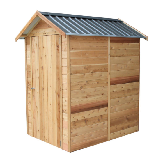
'Windsor' 4x6
S3008
Every part needed to construct your shed is included inside the pack; cedar
panels, doors, windows, hardware kits & roof sheeting. Please ensure you fully
unpack all the parts & check against the parts checklist before contacting
customer service about anything you believe may be missing. Thank-you!
Advertisement

Subscribe to Our Youtube Channel
Related Manuals for STILLA Windsor S3008


Summary of Contents for STILLA Windsor S3008
- Page 1 STILLA ASSEMBLY INSTRUCTIONS ‘Windsor’ 4x6 S3008 Every part needed to construct your shed is included inside the pack; cedar panels, doors, windows, hardware kits & roof sheeting. Please ensure you fully unpack all the parts & check against the parts checklist before contacting...
- Page 2 • Review all instructions; continue to refer to instructions throughout assembly – step by step. Preparing your site • If you are installing your shed on the Stilla heavy duty floor, this can be placed on unlevelled surfaces and levelled up by using the 100x100 stumps provided. P a g e...
- Page 3 23/10/2023 WINDSOR 4x6 PARTS CHECKLIST Part Code Checked Part Description Cedar Clad Panel 900x1895mm Cedar Clad Panel 1200x1895mm Cedar Clad Panel 180x1895mm Single Full Cedar Door 830x1840mm 4ft Gable Cedar Clad Window Panel 900x1895mm (Option) Cedar Shed Window Assembly (add per additional WP option) Corner Post 1890x60x18mm Cover Strip 1890x40x7mm 4ft Fascia Pack (4)
- Page 4 23/10/2023 If no floor option was purchased, go to step 2.0 (Wall Assembly) SKIP TO BACK FOR IMAGES TO HELP WITH FLOOR INSTALL STEP 1.0 FLOOR KIT 1.0 – FLOOR KIT PART CODE QTY DESCRIPTION End Plate 1800mm Single Joist 1214mm Double Joist 1214mm 100BS 100mm Batten Screw...
- Page 5 23/10/2023 STEP 1.1 FLOOR FRAME INSTALLATION The 6x6 floor frame comes in one part. Install floor frame in desired position at desired height and fasten to logs once level and square. 1.1 – FLOOR FRAME INSTALLATION PART CODE QTY DESCRIPTION Logs 750x100x100mm 100BS 100mm batten screws...
-
Page 6: Floor Installation
23/10/2023 STEP 1.2 FLOOR INSTALLATION 1.2 – FLOORING INSTALLATION PART CODE QTY DESCRIPTION Floor Board 1713x800mm Floor Board 1713x395mm 50PS 50mm Philips Screw 1.2– FLOORING INSTALLATION Fasten floor sheets to floor frame as shown in diagram below using 50PS. Bring Floor sheets in 43mm on all 4 sides from the outside of the floor frame. Note- The x marked on the floor sheets do not line up with out joists. -
Page 7: Wall Assembly
23/10/2023 STEP 2.0 WALL ASSEMBLY 2.0 - ASSEMBLY PARTS – WALL ASSEMBLY PART CODE QTY DESCRIPTION Front Wall panel 900mm Wall panel 65HHS 65mm Hex head screw – If optional window was purchased, it can take the place of any 900mm (9P) panel. 2.0 - ASSEMBLY –... - Page 8 23/10/2023 STEP 2.1 WALL ASSEMBLY 2.1 - ASSEMBLY PARTS – WALL ASSEMBLY PART CODE QTY DESCRIPTION 900mm Wall panel 65HHS 65mm Hex head screw 2.1 - ASSEMBLY – WALL ASSEMBLY Screw through 9P into 9P (Top, centre & bottom) using 3 x 65HHS, holding studs flush on the inside.
- Page 9 23/10/2023 STEP 2.2 WALL ASSEMBLY 2.2 - ASSEMBLY PARTS – WALL ASSEMBLY PART CODE QTY DESCRIPTION 1200mm Wall panel 65HHS 65mm Hex head screw 2.2 - ASSEMBLY – WALL ASSEMBLY Screw through 12P into 9P (Top, centre & bottom) using 3 x 65HHS, holding studs flush on the outside.
- Page 10 23/10/2023 STEP 2.3 WALL ASSEMBLY 2.3 - ASSEMBLY PARTS – WALL ASSEMBLY PART CODE QTY DESCRIPTION 900mm Wall panel 65HHS 65mm Hex head screw 2.3 - ASSEMBLY – WALL ASSEMBLY Screw through 12P into 9P (top, centre & bottom) using 3 x 65HHS holding studs flush on the outside.
- Page 11 23/10/2023 STEP 2.4 WALL ASSEMBLY 2.4 - ASSEMBLY PARTS – WALL ASSEMBLY PART CODE QTY DESCRIPTION 900mm Wall panel 65HHS 65mm Hex head screw 2.4 - ASSEMBLY – WALL ASSEMBLY Screw through 9P into 9P (top, centre & bottom) using 3 x 65HHS holding studs flush on the inside.
- Page 12 23/10/2023 STEP 2.5 WALL ASSEMBLY 2.5 - ASSEMBLY PARTS – WALL ASSEMBLY PART CODE QTY DESCRIPTION Front Wall panel 65HHS 65mm Hex head screw 2.5 - ASSEMBLY – WALL ASSEMBLY Screw through FP into 9P (top, centre & bottom) using 3 x 65HHS holding studs flush on the outside.
- Page 13 23/10/2023 STEP 2.6 DOOR STEP INSTALL 2.6 - ASSEMBLY PARTS – DOOR STEP INSTALL PART CODE QTY DESCRIPTION 840x42x19mm Door Step 40mm Nail 2.6 - ASSEMBLY – DOOR STEP INSTALL Nail Door Step in position using 4x 40N* as seen below. Ensure wall panels are tight against DS. * This is if floor option was chosen.
- Page 14 23/10/2023 STEP 2.7 DOOR HEAD ASSEMBLY 2.7 - ASSEMBLY PARTS – DOOR HEAD ASSEMBLY PART CODE QTY DESCRIPTION 840x70x45mm Single Door Head 65HHS 65mm Hex head screw 2.7 - ASSEMBLY – DOOR HEAD ASSEMBLY Hold SDH (or DDH) flush with top of panels. Ensure top cedar tongue on door head at front lines up with top cedar tongue of Front panel.
- Page 15 23/10/2023 STEP 2.8 GABLE INSTALL 2.8 - ASSEMBLY PARTS – GABLE INSTALL PART CODE QTY DESCRIPTION 4ft Gable 65HHS 65mm Hex head screw 2.8 - ASSEMBLY – BACK GABLE INSTALL Carefully position Gable in place, carefully inserting gable groove onto tongue on back panels.
-
Page 16: Roof Frame Assembly
23/10/2023 STEP 3.0 ROOF FRAME ASSEMBLY 3.0 - ASSEMBLY PARTS – ROOF ASSEMBLY (REPEAT TWICE) PART CODE QTY DESCRIPTION Roof End Plate 1714x70x45mm Roof Rafter 580x70x45mm 75BS 75mm Batten Screw 3.0- ASSEMBLY – ROOF ASSEMBLY (1 of 2 frames) It helps to find a flat, level surface to complete this process on. 1. - Page 17 23/10/2023 STEP 3.1 ROOF ASSEMBLY 3.1 - ASSEMBLY PARTS – ROOF ASSEMBLY (ROOF SHEETS) PART CODE QTY DESCRIPTION 880mm roof sheet 40RS 40mm Roof screw 25RS 25mm Roof screw 3.1 - ASSEMBLY – ROOF ASSEMBLY (ROOF SHEETS) It helps to find a flat, level surface to complete this process on. Position roof sheets (RS) at either end of roof frame and fasten in place as indicated in diagrams.
- Page 18 23/10/2023 STEP 3.2 ROOF ASSEMBLY 3.2 - ASSEMBLY PARTS – ROOF ASSEMBLY (ROOF SHEETS) PART CODE QTY DESCRIPTION 880mm roof sheet 40RS 40mm Roof screw 25RS 25mm Roof screw 3.2 - ASSEMBLY – ROOF ASSEMBLY (ROOF SHEETS) Complete laying roof sheeting out on frame. Fasten roof sheets to battens in sequence shown.
- Page 19 23/10/2023 STEP 3.3 ROOF ASSEMBLY 3.3 - ASSEMBLY PARTS – ROOF ASSEMBLY PART CODE QTY DESCRIPTION 40RS 40mm Roof screw 25RS 25mm Roof screw 3.3 - ASSEMBLY – ROOF ASSEMBLY Complete screwing roof off at top. 1 x 25RS in pan beside every rib. Once top is complete screw bottom off using 1 x 40RS through every rib.
- Page 20 23/10/2023 STEP 3.4 CHANNEL ASSEMBLY If you purchased the Lean-To/Annex, leave the channel off the side you will be installing your Lean-To/Annex 3.4 - ASSEMBLY PARTS – CHANNEL ASSEMBLY PART CODE QTY DESCRIPTION 12mm self-tapping screw Roof Channel 3.4 - ASSEMBLY – CHANNEL ASSEMBLY Slide Roof channel onto end of roof sheeting overhang.
- Page 21 23/10/2023 STEP 3.5 ROOF END PIECE 3.5 - ASSEMBLY PARTS – RIDGE BEAM BRACKET PART CODE QTY DESCRIPTION Roof End Piece 203x70x30mm 65BS 65 Batten Screws 3.5 - ASSEMBLY – ROOF END PIECES TO GABLES Standing inside shed on ladder, screw roof end pieces to top of gable in required positions using 1x 65BS per piece.
-
Page 22: Roof Installation
23/10/2023 STEP 3.6 ROOF INSTALLATION 3.6 - ASSEMBLY PARTS – ROOF INSTALLATION PART CODE QTY DESCRIPTION Completed roof panels 75BS 75mm Batten Screw 3.6 - ASSEMBLY – ROOF INSTALLATION Slide roof frame into position. Ensure point of roof frame is flush with middle of gable as seen below. - Page 23 23/10/2023 STEP 3.7 ROOF INSTALATION 3.7 - ASSEMBLY – ROOF INSTALLATION PART CODE QTY DESCRIPTION 40RS 40mm Roof Screws 25RS 25mm Roof Screws 3.7 – ASSEMBLY – ROOF INSTALLATION Fully fasten down the roof sheeting onto the Roof End Pieces (E) as seen below. Use 2x 25RS to screw into the top E of each side and 2x 40RS to screw into the bottom E of each side.
- Page 24 23/10/2023 STEP 3.8 ROOF JOIN 3.8 – ASSEMBLY PARTS – COLLAR TIE INSTALLATION PART CODE QTY DESCRIPTION 125BS 125mm Batten Screw 3.8- ASSEMBLY – COLLAR TIE INSTALLATION Fasten roof frames together by screwing 125BS evenly space along the top of the roof frames.
- Page 25 23/10/2023 STEP 5.0 SINGLE DOOR HINGE ASSEMBLY 5.0 - ASSEMBLY PARTS – SINGLE DOOR HINGE ASSEMBLY PART CODE DESCRIPTION Hinge Hinge Screw Door 5.0 - ASSEMBLY – SINGLE DOOR HINGE ASSEMBLY Place door on back and hold hinge (H) in position. Fasten hinges to outside of door as seen below using 3x hinge screws (HS) per hinge.
- Page 26 23/10/2023 STEP 5.1 SINGLE DOOR INSTALLATION 5.1 - ASSEMBLY PARTS – SINGLE DOOR INSTALLATION PART CODE DESCRIPTION Single Colonial Door Hinge screw 5.1 - ASSEMBLY – SINGLE DOOR INSTALLATION Hold door in position, 3mm down from top. Front of the door when closed will be flush with front of VJ cladding.
- Page 27 23/10/2023 STEP 5.2 SINGLE DOOR HANDLE ASSEMBLY 5.2 - ASSEMBLY PARTS – SINGLE DOOR HANDLE ASSEMBLY PART CODE QTY DESCRIPTION T Handle kit 5.2 - ASSEMBLY – SINGLE DOOR HANDLE ASSEMBLY 1. Remove bolts and leaver from back of T Handle (TH). 2.
- Page 28 23/10/2023 If no Additional Window panels please go to step 6.0 STEP 5.4 WINDOW ASSEMBLY INSTALLATION 5.9 - ASSEMBLY PARTS – WINDOW ASSEMBLY INSTALLATION PART CODE QTY DESCRIPTION Window Assembly 32PS 32mm Phillips screw 5.9 - ASSEMBLY – WINDOW ASSEMBLY INSTALLATION Fit Window Assembly into hole in Window Panel*.
- Page 29 23/10/2023 STEP 5.5 IINTERNAL WINDOW STRIP ASSEMBLY 6.0 - ASSEMBLY PARTS – INTERNAL WINDOW STRIP ASSEMBLY PART CODE QTY DESCRIPTION SIWS Internal Window Strip Set- 2@ 770mm, 2@ 735mm 40mm Nail 6.0 - ASSEMBLY – INTERNAL WINDOW STRIP ASSEMBLY 1. Measure 25mm around perimeter of Window Panel hole. 2.
- Page 30 23/10/2023 STEP 6.0 CORNER POST ASSEMBLY 6.0 - ASSEMBLY PARTS – CORNER POST ASSEMBLY PART CODE QTY DESCRIPTION 1890mm Corner Post 40mm Nail 6.0 - ASSEMBLY – CORNER POST ASSEMBLY Hold corner post (CP) in position, nail through CP into wall stud using 6x 40N evenly spaced along CP.
- Page 31 23/10/2023 STEP 6.1 COVER STRIP ASSEMBLY 6.1 - ASSEMBLY PARTS – COVER STRIP ASSEMBLY PART CODE QTY DESCRIPTION 1890mm Cover Strip 40mm Nail 6.1 - ASSEMBLY – COVER STRIP ASSEMBLY Hold cover strips (CS) over joins in walls, nail through CS into wall panel using 6x 40N evenly spaced per CS.
- Page 32 23/10/2023 STEP 6.2 FASCIA ASSEMBLY 6.2 - ASSEMBLY PARTS – FASCIA ASSEMBLY PART CODE QTY DESCRIPTION Fascia 40mm Nail 6.2 - ASSEMBLY – FASCIA ASSEMBLY Hold fascia’s in position. Flush with bottom of battens and meeting evenly at the top. Nail into end of Battens.
- Page 33 23/10/2023 STEP 6.4 6.4 - ASSEMBLY PARTS – FIXING TO BASE PART CODE QTY DESCRIPTION 65HHS 65mm Hex Head Screw 6.4 - ASSEMBLY – FIXING TO BASE Once shed is in desired position and doors are sitting evenly you can now fix your shed to the base.
- Page 34 23/10/2023 IMAGES TO HELP WITH INSTALLATION FLOOR 33 | P a g e...
- Page 35 23/10/2023 34 | P a g e...
- Page 36 23/10/2023 35 | P a g e...
- Page 37 23/10/2023 36 | P a g e...
- Page 38 23/10/2023 37 | P a g e...
-
Page 39: Product Maintenance
23/10/2023 TO REGISTER YOUR WARRANTY Thank-you for purchasing a STILLA product. To register your 10 year product warranty, please go to www.stilla.com.au/warranty and complete the online form. We recommend that you complete this step once you have finished installing your product. - Page 40 23/10/2023 SHOW US YOUR SHED We would love to see a photo of your STILLA product installed in your backyard. Please upload this image when completing the warranty registration. Alternatively, you can send the photos by email to sales@stilla.com.au. If you require any assistance, please feel free to call or email.
Need help?
Do you have a question about the Windsor S3008 and is the answer not in the manual?
Questions and answers