Advertisement
Quick Links
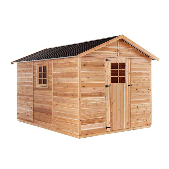
STILLA
ASSEMBLY INSTRUCTIONS
'Master' 8x12
S3041
Every part needed to construct your shed is included inside the pack; cedar
panels, doors, windows, hardware kits & roof sheeting. Please ensure you fully
unpack all the parts & check against the parts checklist before contacting
customer service about anything you believe may be missing. Thank-you!
Advertisement

Related Manuals for STILLA Master


Summary of Contents for STILLA Master
- Page 1 STILLA ASSEMBLY INSTRUCTIONS ‘Master’ 8x12 S3041 Every part needed to construct your shed is included inside the pack; cedar panels, doors, windows, hardware kits & roof sheeting. Please ensure you fully unpack all the parts & check against the parts checklist before contacting...
- Page 2 • Review all instructions; continue to refer to instructions throughout assembly – step by step. Preparing your site • If you are installing your shed on the Stilla heavy duty floor, this can be placed on unlevelled surfaces and levelled up by using the 100x100 stumps provided. P a g e...
- Page 3 Internal Window Strip Set – 2@ 770mm, 2@ 735mm (add per additional WP) Front Gable Cover Strip – 460mm Back Gable Cover Strip – 490mm Stilla Cover Strip 2400x40x7mm (1@ 1800mm, 1@ 600mm) 1 & 1 Roof Support Block 250x70x45mm Roof End Piece 203x70x30mm...
- Page 4 19/10/2023 Floor Kit – Option Floor Frame – 140x35 Part Code Checked Part Description End Plate 1242mm Double Joist 1730mm Single Joist 1730mm Floor Nog 379x42x35mm Logs 750mm 1798mm x 800mm 598mm x 800mm 1798mm x 311mm 598mm x 311mm P a g e...
- Page 5 19/10/2023 If no floor option was purchased, go to step 2.0 (Wall Assembly) SKIP TO BACK FOR IMAGES TO HELP WITH FLOOR INSTALL STEP 1.0 FLOOR KIT 1.0 – FLOOR KIT (1 of 4 floor frames) PART CODE QTY DESCRIPTION End Plate 1242mm Single Joist 1730mm Double Joist 1730mm...
- Page 6 19/10/2023 STEP 1.1 FLOOR FRAME INSTALLATION The 8x12 floor frame comes in four parts. Install first floor frame in desired position at desired height and fasten to logs once level and square, then join and fasten next frame until all four are joined and secured to logs. 1.1 –...
- Page 7 19/10/2023 STEP 1.2 FLOOR NOG INSTALLATION 1.2 – FLOOR NOG INSTALLATION PART CODE QTY DESCRIPTION Floor Nog 379x42x35mm 65HHS 65mm Hex Head Screws 1.2 – FLOOR NOG INSTALLATION Mark out measurements shown below (centre of nog). Fasten Floor Nogs (FN) in positions shown in diagram below using 1x 65HHS per join.
- Page 8 19/10/2023 STEP 1.3 FLOOR INSTALLATION 1.3 – FLOORING INSTALLATION PART CODE QTY DESCRIPTION Floor Board 1798x800mm Floor Board 598x800mm Floor Board 1798x311mm Floor Board 598x311mm 50PS 50mm Philips Screw 1.3– FLOORING INSTALLATION Fasten floor sheets to floor frame as shown in diagram below using 50PS. Bring Floor sheets in 43mm on all 4 sides from the outside of the floor frame.
- Page 9 19/10/2023 STEP 2.0 WALL ASSEMBLY WALL PANEL (WP) (900MM WINDOW PANEL) CAN BE POSITIONED ANYWHERE ON THE SHED WHERE WE HAVE USED A (P) (900MM WALL PANEL). 2.0 - ASSEMBLY PARTS – WALL ASSEMBLY PART CODE QTY DESCRIPTION Front wall panel 900mm Wall panel 65HHS 65mm Hex head screw...
- Page 10 19/10/2023 STEP 2.1 WALL ASSEMBLY 2.1 - ASSEMBLY PARTS – WALL ASSEMBLY PART CODE QTY DESCRIPTION 900mm Wall panel 65HHS 65mm Hex head screw 2.1 - ASSEMBLY PARTS – WALL ASSEMBLY Screw through P into P (Top, centre & bottom) using 3 x 65HHS, holding studs flush on the inside.
- Page 11 19/10/2023 STEP 2.2 WALL ASSEMBLY 2.2 - ASSEMBLY PARTS – WALL ASSEMBLY PART CODE QTY DESCRIPTION 900mm Wall panel 65HHS 65mm Hex head screw 2.2 - ASSEMBLY PARTS – WALL ASSEMBLY Screw through P into P (Top, centre & bottom) using 3 x 65HHS, holding studs flush on the inside –...
- Page 12 19/10/2023 STEP 2.3 WALL ASSEMBLY 2.3 - ASSEMBLY PARTS – WALL ASSEMBLY PART CODE QTY DESCRIPTION 1200mm Wall panel 65HHS 65mm Hex head screw 2.3 - ASSEMBLY PARTS – WALL ASSEMBLY Screw through P into P (Top, centre & bottom) using 3 x 65HHS, holding studs flush on the outside.
- Page 13 19/10/2023 STEP 2.4 WALL ASSEMBLY 2.4 - ASSEMBLY PARTS – WALL ASSEMBLY PART CODE QTY DESCRIPTION 1200mm Wall panel 65HHS 65mm Hex head screw 2.4 - ASSEMBLY PARTS – WALL ASSEMBLY Screw through P into P (top, centre & bottom) using 3 x 65HHS holding studs flush on the inside.
- Page 14 19/10/2023 STEP 2.5 WALL ASSEMBLY 2.5 - ASSEMBLY PARTS – WALL ASSEMBLY PART CODE QTY DESCRIPTION 900mm Wall panel 65HHS 65mm Hex head screw 2.5 - ASSEMBLY PARTS – WALL ASSEMBLY Screw through P into P (top, centre & bottom) using 3 x 65HHS holding studs flush on the outside.
- Page 15 19/10/2023 STEP 2.6 WALL ASSEMBLY 2.6 - ASSEMBLY PARTS – WALL ASSEMBLY PART CODE QTY DESCRIPTION 900mm Window panel 65HHS 65mm Hex head screw 2.6 - ASSEMBLY PARTS – WALL ASSEMBLY Screw through WP into P (top, centre & bottom) using 3 x 65HHS holding studs flush on the inside.
- Page 16 19/10/2023 STEP 2.7 WALL ASSEMBLY 2.7 - ASSEMBLY PARTS – WALL ASSEMBLY PART CODE QTY DESCRIPTION 900mm Wall panel 65HHS 65mm Hex head screw 2.7 - ASSEMBLY PARTS – WALL ASSEMBLY Screw through P into WP (top, centre & bottom) using 3 x 65HHS holding studs flush on the inside –...
- Page 17 19/10/2023 STEP 2.8 WALL ASSEMBLY 2.8 - ASSEMBLY PARTS – WALL ASSEMBLY PART CODE QTY DESCRIPTION Front wall panel 65HHS 65mm Hex head screw 2.8 - ASSEMBLY PARTS – WALL ASSEMBLY Screw through FP into P (top, centre & bottom) using 3 x 65HHS holding studs flush on the outside.
- Page 18 19/10/2023 STEP 2.9 DOOR STEP INSTALL 2.9 - ASSEMBLY PARTS – DOOR STEP INSTALL PART CODE QTY DESCRIPTION 840x42x19mm Single Door Step (Replace with 1440 DS if DD) 1440x42x19mm Double Door Step (ONLY FOR DD OPTION) 40mm Nail 2.9 - ASSEMBLY – DOOR STEP INSTALL Nail Door Step in position using 4x 40N* as seen below.
- Page 19 19/10/2023 STEP 3.0 DOOR HEAD ASSEMBLY 3.0 - ASSEMBLY PARTS – DOOR HEAD ASSEMBLY PART CODE QTY DESCRIPTION 840x70x45mm Single Door Head (replace with 1440mm DH if DD) 1440x70x45mm Double Door Head (ONLY FOR DD OPTION) 65HHS 65mm Hex head screw 3.0 - ASSEMBLY –...
- Page 20 19/10/2023 STEP 3.1 BACK END GABLE ASSEMBLY 3.1 - ASSEMBLY PARTS – BACK END GABLE ASSEMBLY PART CODE QTY DESCRIPTION 8ft Gable (left and right) 490mm Back Gable Cover Strip 65HHS 65mm Hex head screw 40mm Nail 3.1 - ASSEMBLY – BACK END GABLE ASSEMBLY Lay left and right gables (G) on a flat surface with the frame facing upwards, as seen below.
- Page 21 19/10/2023 STEP 3.2 BACK END GABLE INSTALL 3.2 - ASSEMBLY PARTS – BACK END GABLE INSTALL PART CODE QTY DESCRIPTION Assembled back end 8ft Gable 65HHS 65mm Hex head screw 3.2 - ASSEMBLY – BACK END GABLE INSTALL Carefully place assembled gable on back wall, ensuring groove on gable slots into the tongue on the wall, as seen below.
- Page 22 3.3 - ASSEMBLY PARTS – FRONT END GABLE ASSEMBLY PART CODE QTY DESCRIPTION 8ft Gable (left and right) 1 & 1 Stilla Cover Strip (1@1800mm, 1@ 600mm) 460mm Front Gable Cover Strip 65HHS 65mm Hex head screw 40mm Nail 3.3 - ASSEMBLY – FRONT END GABLE ASSEMBLY Lay left and right gables (G) on a flat surface with the frame facing upwards, as seen below.
- Page 23 19/10/2023 STEP 3.4 FRONT END GABLE INSTALL 3.4 - ASSEMBLY PARTS – FRONT END GABLE INSTALL PART CODE QTY DESCRIPTION Assembled front end 8ft Gable 65HHS 65mm Hex head screw 3.4 - ASSEMBLY – FRONT END GABLE INSTALL Carefully position Gable in place, carefully inserting gable groove onto tongues on front panels and door head.
- Page 24 19/10/2023 STEP 3.4 ROOF SUPPORT BLOCK INSTALL 3.4 - ASSEMBLY PARTS –ROOF SUPPORT BLOCK INSTALL PART CODE QTY DESCRIPTION Roof Support Block 250x70x45 75BS 75mm Batten Screw 3.4 - ASSEMBLY –ROOF SUPPORT BLOCK INSTALL Place Roof Support Block flush with bottom of top gable frames as seen in photo below. Screw to gable frame using 2x 75BS per RSB*.
- Page 25 19/10/2023 STEP 4.0 ROOF FRAME ASSEMBLY 4.0 - ASSEMBLY PARTS – ROOF ASSEMBLY (REPEAT TWICE) PART CODE QTY DESCRIPTION Roof End Plate 1754x70x45mm Roof Rafter 1195x70x45mm Joining Plate 1112x70x45mm 75BS 75mm Batten Screw 4.0 - ASSEMBLY – ROOF ASSEMBLY (1 of 2 frames) It helps to find a flat, level surface to complete this process on.
- Page 26 19/10/2023 STEP 4.1 ROOF INSULATION INSTALL If you did not purchase this option please skip this step 4.1 - ASSEMBLY PARTS – ROOF INSULATION INSTALL (REPEAT TWICE) PART CODE QTY DESCRIPTION RI (option) Roof Insulation 3600x1300mm 40mm Nail 4.1 - ASSEMBLY – ROOF INSULATION INSTALL (REPEAT WITH SECOND FRAME) It helps to find a flat, level surface to complete this process on.
- Page 27 19/10/2023 STEP 4.2 ROOF ASSEMBLY 4.2 - ASSEMBLY PARTS – ROOF ASSEMBLY (ROOF SHEETS) PART CODE QTY DESCRIPTION 1450mm roof sheet 40RS 40mm Roof screw 25RS 25mm Roof screw 4.2 - ASSEMBLY – ROOF ASSEMBLY (ROOF SHEETS) It helps to find a flat, level surface to complete this process on. Position roof sheets (RS) at either end of roof frame and fasten in place as indicated in diagrams.
- Page 28 19/10/2023 STEP 4.3 ROOF ASSEMBLY 4.3 - ASSEMBLY PARTS – ROOF ASSEMBLY (ROOF SHEETS) PART CODE QTY DESCRIPTION 1450mm roof sheet 1450mm single pan roof sheet 40RS 40mm Roof screw 25RS 25mm Roof screw 4.3 - ASSEMBLY – ROOF ASSEMBLY (ROOF SHEETS) Complete laying roof sheeting out on frame.
- Page 29 19/10/2023 STEP 4.4 ROOF ASSEMBLY 4.4 - ASSEMBLY PARTS – ROOF ASSEMBLY PART CODE QTY DESCRIPTION 40RS 40mm Roof screw 25RS 25mm Roof screw 4.4 - ASSEMBLY – ROOF ASSEMBLY Complete screwing roof off at top. 1 x 25RS in pan beside every rib. Once top is complete screw bottom off using 1 x 40RS through every rib.
- Page 30 19/10/2023 STEP 4.5 CHANNEL ASSEMBLY If you purchased the Annex, leave the channel off the side you will be installing your Annex 4.5 - ASSEMBLY PARTS – CHANNEL ASSEMBLY PART CODE QTY DESCRIPTION 12mm self-tapping screw Roof Channel 4.5 - ASSEMBLY – CHANNEL ASSEMBLY Slide Roof channel onto end of roof sheeting overhang.
- Page 31 19/10/2023 STEP 4.6 ROOF END PIECE 4.6 - ASSEMBLY PARTS – RIDGE BEAM BRACKET PART CODE QTY DESCRIPTION Roof End Piece 203x70x30mm 65BS 65 Batten Screws 4.6 - ASSEMBLY – ROOF END PIECES TO GABLES Standing inside shed on ladder, screw roof end pieces to top of gable in required positions using 1x 65BS per piece.
- Page 32 19/10/2023 STEP 4.7 ROOF INSTALLATION 4.7 - ASSEMBLY PARTS – ROOF INSTALLATION PART CODE QTY DESCRIPTION Completed roof panels 75BS 75mm Batten Screw 125BS 125mm Batten Screw 4.7 - ASSEMBLY – ROOF INSTALLATION Slide roof frame into position. Ensure point of roof frame is flush with middle of gable as seen below.
- Page 33 19/10/2023 STEP 4.8 ROOF INSTALATION 4.8 - ASSEMBLY – ROOF INSTALLATION PART CODE QTY DESCRIPTION 40RS 40mm Roof Screws 25RS 25mm Roof Screws 4.8 – ASSEMBLY – ROOF INSTALLATION Fully fasten down the roof sheeting onto the Roof End Pieces (E) as seen below. Use 2x 25RS to screw into the top E of each side and 2x 40RS to screw into the bottom E of each side.
- Page 34 19/10/2023 STEP 4.9 COLLAR TIE INSTALLATION 4.9 – ASSEMBLY PARTS – COLLAR TIE INSTALLATION PART CODE QTY DESCRIPTION Collar tie 40RS 40mm Roof Screw 125BS 125mm Batten Screw 4.9- ASSEMBLY – COLLAR TIE INSTALLATION Holding Collar tie tight and level in position screw through CT into Roof Rafters in predrilled holes, using 6x 40RS per collar tie.
- Page 35 19/10/2023 If Double door option was chosen please go to step 5.4 STEP 5.0 SINGLE DOOR HINGE ASSEMBLY 5.0 - ASSEMBLY PARTS – SINGLE DOOR HINGE ASSEMBLY PART CODE DESCRIPTION Hinge Hinge Screw Door 5.0 - ASSEMBLY – SINGLE DOOR HINGE ASSEMBLY Place door on back and hold hinge (H) in position.
- Page 36 19/10/2023 STEP 5.1 SINGLE DOOR INSTALLATION 5.1 - ASSEMBLY PARTS – SINGLE DOOR INSTALLATION PART CODE DESCRIPTION Single Colonial Door Hinge screw 5.1 - ASSEMBLY – SINGLE DOOR INSTALLATION Hold door in position, 3mm down from top. Front of the door when closed will be flush with front of VJ cladding.
- Page 37 19/10/2023 STEP 5.2 SINGLE DOOR HANDLE ASSEMBLY 5.2 - ASSEMBLY PARTS – SINGLE DOOR HANDLE ASSEMBLY PART CODE QTY DESCRIPTION T Handle kit 5.2 - ASSEMBLY – SINGLE DOOR HANDLE ASSEMBLY 1. Remove bolts and leaver from back of T Handle (TH). 2.
- Page 38 19/10/2023 If Double door option was not chosen please go to step 5.9 STEP 5.4 DOUBLE DOOR HINGE ASSEMBLY 5.4 - ASSEMBLY PARTS – DOUBLE DOOR HINGE ASSEMBLY PART CODE DESCRIPTION Hinge Hinge Screw Double Colonial Doors 5.0 - ASSEMBLY – DOUBLE DOOR HINGE ASSEMBLY Place door on back and hold hinge (H) in position.
- Page 39 19/10/2023 STEP 5.5 DOUBLE DOOR INSTALLATION 5.5 - ASSEMBLY PARTS – DOUBLE DOOR INSTALLATION PART CODE DESCRIPTION Doors Hinge screw 5.5 - ASSEMBLY – DOUBEL DOOR INSTALLATION Hold door in position, 3mm down from top. Front of the door when closed will be flush with front of VJ cladding.
- Page 40 19/10/2023 STEP 5.6 PAD BOLT INSALLATION 5.6 - ASSEMBLY PARTS – PAD BOLT INSTALLATION PART CODE DESCRIPTION Pad bolt Pad bolt screws 5.6 - ASSEMBLY – PAD BOLT INSTALLATION Choose fixed door (generally left hand door). Hold top Pad bolt in position and fasten to door using 4x PBS.
- Page 41 19/10/2023 STEP 5.7 DOUBLE DOOR HANDLE ASSEMBLY 5.7 - ASSEMBLY PARTS – DOUBLE DOOR HANDLE ASSEMBLY PART CODE QTY DESCRIPTION T Handle kit 5.7 - ASSEMBLY – DOUBLE DOOR HANDLE ASSEMBLY 1. Remove bolts and leaver from back of T Handle (TH). 2.
- Page 42 19/10/2023 STEP 5.8 DOOR HANDLE ASSEMBLY 5.8 - ASSEMBLY PARTS – DOUBLE DOOR HANDLE ASSEMBLY PART CODE QTY DESCRIPTION Door Packer 40mm Nail T Handle Leaver / backing tongue 5.8 - ASSEMBLY – DOUBLE DOOR HANDLE ASSEMBLY Holding DP in position, fasten to fixed door (door with pad bolts) using 4x 40N. Holding door in closed position, flush with other door - slide leaver onto T Handle and tighten once hitting packer on fixed door.
- Page 43 19/10/2023 STEP 5.9 WINDOW ASSEMBLY INSTALLATION 5.9 - ASSEMBLY PARTS – WINDOW ASSEMBLY INSTALLATION PART CODE QTY DESCRIPTION Window Assembly 32PS 32mm Phillips screw 5.9 - ASSEMBLY – WINDOW ASSEMBLY INSTALLATION Fit Window Assembly into hole in Window Panel*. Ensuring the window frame is square, fasten to Window Panel by screwing through perimeter of Window Panel hole into WA**.
- Page 44 19/10/2023 STEP 6.0 IINTERNAL WINDOW STRIP ASSEMBLY 6.0 - ASSEMBLY PARTS – INTERNAL WINDOW STRIP ASSEMBLY PART CODE QTY DESCRIPTION SIWS Internal Window Strip Set- 2@ 770mm, 2@ 735mm 40mm Nail 6.0 - ASSEMBLY – INTERNAL WINDOW STRIP ASSEMBLY 1. Measure 25mm around perimeter of Window Panel hole. 2.
- Page 45 19/10/2023 STEP 6.1 CORNER POST ASSEMBLY 6.1 - ASSEMBLY PARTS – CORNER POST ASSEMBLY PART CODE QTY DESCRIPTION 1890mm Corner Post 40mm Nail 6.1 - ASSEMBLY – CORNER POST ASSEMBLY Hold corner post (CP) in position, nail through CP into wall stud using 6x 40N evenly spaced along CP.
- Page 46 19/10/2023 STEP 6.2 COVER STRIP ASSEMBLY 6.2 - ASSEMBLY PARTS – COVER STRIP ASSEMBLY PART CODE QTY DESCRIPTION 1890mm Cover Strip 40mm Nail 6.2 - ASSEMBLY – COVER STRIP ASSEMBLY Hold cover strips (CS) over joins in walls, nail through CS into wall panel using 6x 40N evenly spaced per CS.
- Page 47 19/10/2023 STEP 6.3 FASCIA ASSEMBLY 6.3 - ASSEMBLY PARTS – FASCIA ASSEMBLY PART CODE QTY DESCRIPTION Fascia 40mm Nail 6.3 - ASSEMBLY – FASCIA ASSEMBLY Hold fascia’s in position. Flush with bottom of battens and joining evenly at the top. STEP 6.4 RIDGE CAP INSTALLATION 6.4 - ASSEMBLY PARTS –...
- Page 48 19/10/2023 STEP 6.5 FIXING TO BASE 6.5 - FIXING TO BASE PART CODE QTY DESCRIPTION 65HHS 65mm Hex head screw 6.5 - FIXING TO BASE Screw through base plates on wall frames in positions shown below using 65HHS screws. If floor not purchased fixings are not provided Screw 3 x 65HHS (Top, centre &...
- Page 49 19/10/2023 IMAGES TO HELP WITH INSTALLATION FLOOR 48 | P a g e...
- Page 50 19/10/2023 49 | P a g e...
- Page 51 19/10/2023 50 | P a g e...
- Page 52 19/10/2023 51 | P a g e...
- Page 53 19/10/2023 52 | P a g e...
- Page 54 19/10/2023 53 | P a g e...
-
Page 55: Product Maintenance
19/10/2023 TO REGISTER YOUR WARRANTY Thank-you for purchasing a STILLA product. To register your 10 year product warranty, please go to www.stilla.com.au/warranty and complete the online form. We recommend that you complete this step once you have finished installing your product. - Page 56 19/10/2023 SHOW US YOUR SHED We would love to see a photo of your STILLA product installed in your backyard. Please upload this image when completing the warranty registration. Alternatively, you can send the photos by email to sales@stilla.com.au. If you require any assistance, please feel free to call or email.
Need help?
Do you have a question about the Master and is the answer not in the manual?
Questions and answers