STILLA Windsor S3008 Assembly Instructions Manual
4x6
Hide thumbs
Also See for Windsor S3008:
- Assembly instructions manual (40 pages) ,
- Assembly instructions manual (40 pages)
Advertisement
Quick Links
STILLA
ASSEMBLY INSTRUCTIONS
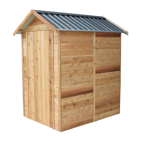
'Windsor' 4x6
S3008
Every part needed to construct your shed is included inside the pack; cedar
panels, doors, windows, hardware kits & roof sheeting. Please ensure you fully
unpack all the parts & check against the parts checklist before contacting
customer service about anything you believe may be missing. Thank-you!
Advertisement

Subscribe to Our Youtube Channel
Related Manuals for STILLA Windsor S3008


Summary of Contents for STILLA Windsor S3008
- Page 1 STILLA ASSEMBLY INSTRUCTIONS ‘Windsor’ 4x6 S3008 Every part needed to construct your shed is included inside the pack; cedar panels, doors, windows, hardware kits & roof sheeting. Please ensure you fully unpack all the parts & check against the parts checklist before contacting...
- Page 2 Caution Please be careful when handling all components, some parts have sharp metal edges. Always wear work gloves, eye protection and long sleeves when assembling or maintaining your shed. Tools required for assembly • Level • Phillips head drive • Drill •...
- Page 3 WINDSOR 4x6 PARTS CHECKLIST Part Code Checked Part Description Cedar Clad Panel 900x1890mm Cedar Clad Panel 1200x1890mm Cedar Clad Panel 180x1890mm 4ft Front Gable 4ft Back Gable Rafters 610mm TB/BB Top Batten/Bottom Batten 2115mm 4x6 Standard Door 830x1875 – Full Cedar 2115mm Channel 880mm Sheeting 4x6 Hardware Kit...
- Page 4 If no floor option was purchased, go to step 2.0 (Wall Assembly) STEP 1.0 FLOOR KIT 1.0 – FLOOR KIT PART CODE QTY DESCRIPTION End Plate 1800mm Single Joist 1200mm Double Joist 1200mm (42x35mm part of DJ goes at the top inside) 100BS 100mm Batten screw (Heavy Duty Floor Only) 75mm Nail (Rebated Floor Only)
- Page 5 STEP 1.1 FLOORING INSTALLATION 1.1 – FLOOR INSTALLATION PART CODE DESCRIPTION Floor Board 1713x800mm Floor Board 1713x395mm 50PS 50mm Philips Screw 1.1 – FLOOR SHEETS Fasten floor sheets to floor frame as shown below using 50PS P a g e...
- Page 6 STEP 2.0 WALL ASSEMBLY 2.0 - ASSEMBLY PARTS – WALL ASSEMBLY PART CODE QTY DESCRIPTION Front Wall panel 900mm Wall panel 65HHS 65mm Hex head screw 2.0 - ASSEMBLY – WALL ASSEMBLY Screw through FP into 9P (top, centre & bottom) using 3 x 65HHS. (Holding studs flush on the outside) Note: Ensure tongue on VJ cladding is facing upwards.
- Page 7 STEP 2.1 WALL ASSEMBLY 2.1 - ASSEMBLY PARTS – WALL ASSEMBLY PART CODE QTY DESCRIPTION 900mm Wall panel 65HHS 65mm Hex head screw 2.1 - ASSEMBLY – WALL ASSEMBLY Screw through 9P into 9P (Top, centre & bottom) using 3 x 65HHS, holding studs flush on the inside.
- Page 8 STEP 2.2 WALL ASSEMBLY 2.2 - ASSEMBLY PARTS – WALL ASSEMBLY PART CODE QTY DESCRIPTION 1200mm Wall panel 65HHS 65mm Hex head screw 2.2 - ASSEMBLY – WALL ASSEMBLY Screw through 12P into 9P (Top, centre & bottom) using 3 x 65HHS, holding studs flush on the outside.
- Page 9 STEP 2.3 WALL ASSEMBLY 2.3 - ASSEMBLY PARTS – WALL ASSEMBLY PART CODE QTY DESCRIPTION 900mm Wall panel 65HHS 65mm Hex head screw 2.3 - ASSEMBLY – WALL ASSEMBLY Screw through 12P into 9P (top, centre & bottom) using 3 x 65HHS holding studs flush on the outside.
- Page 10 STEP 2.4 WALL ASSEMBLY 2.4 - ASSEMBLY PARTS – WALL ASSEMBLY PART CODE QTY DESCRIPTION 900mm Wall panel 65HHS 65mm Hex head screw 2.4 - ASSEMBLY – WALL ASSEMBLY Screw through 9P into 9P (top, centre & bottom) using 3 x 65HHS holding studs flush on the inside.
- Page 11 STEP 2.5 WALL ASSEMBLY 2.5 - ASSEMBLY PARTS – WALL ASSEMBLY PART CODE QTY DESCRIPTION Front Wall panel 65HHS 65mm Hex head screw 2.5 - ASSEMBLY – WALL ASSEMBLY Screw through FP into 9P (top, centre & bottom) using 3 x 65HHS holding studs flush on the outside.
- Page 12 STEP 2.6 BACK GABLE ASSEMBLY 2.6 - ASSEMBLY PARTS – GABLE ASSEMBLY PART CODE QTY DESCRIPTION Back gable 65HHS 65mm Hex head screw 2.6 - ASSEMBLY – GABLE ASSEMBLY Carefully position BG in place inserting tongue on back panels into groove in BG. Screw up through wall panels into bottom plate of gable using 3 x 65HHS at ends and centre.
- Page 13 STEP 2.7 FRONT GABLE ASSEMBLY 2.7 - ASSEMBLY PARTS – GABLE ASSEMBLY PART CODE QTY DESCRIPTION Front gable 65HHS 65mm Hex head screw 2.7 - ASSEMBLY – GABLE ASSEMBLY Carefully position FG in place inserting tongue on front walls into groove in FG. Screw up through wall panels into bottom plate of gable using 4 x 65HHS.
- Page 14 STEP 3.1 ROOF ASSEMBLY 3.1 - ASSEMBLY PARTS – ROOF ASSEMBLY PART CODE QTY DESCRIPTION Roof sheets 40RS 40mm roof screw 25RS 25mm roof screw 3.1 - ASSEMBLY – ROOF ASSEMBLY Lay roof frame on a hard flat surface. Position 1 roof sheet (RS) at each end of frame, flush at top and flush with end of roof battens.
- Page 15 STEP 3.2 ROOF ASSEMBLY 3.2 - ASSEMBLY PARTS – ROOF ASSEMBLY PART CODE QTY DESCRIPTION Roof sheets 40RS 40mm roof screw 25RS 25mm roof screw 3.2 - ASSEMBLY– ROOF ASSEMBLY Fasten roof sheet (RS) to frame in sequence shown. 1 x 25RS either side of join at top and 1 x 40RS through rib join at bottom Bent up edge at top.
- Page 16 STEP 3.3 ROOF ASSEMBLY 3.3 - ASSEMBLY PARTS – ROOF ASSEMBLY PART CODE QTY DESCRIPTION 40RS 40mm roofing screw 25RS 25mm roof screw 3.3 - ASSEMBLY– ROOF ASSEMBLY Complete screwing off roof at top 1 x 25RS beside every rib. Once top complete, screw bottom off using 1 x 40RS in every rib.
- Page 17 STEP 3.4 ROOF ASSEMBLY 3.4 - ASSEMBLY PARTS – ROOF ASSEMBLY PART CODE QTY DESCRIPTION 2115mm Channel Self-tapping screw 3.4 - ASSEMBLY – ROOF ASSEMBLY Slide channel onto roof (C) Fasten channel (2115C) to roof using ST x 4 in positions shown. 1 rib in 1 rib in Sheet join...
- Page 18 STEP 3.5 ROOF INSTALLATION 3.5 - ASSEMBLY PARTS – ROOF INSTALLATION PART CODE QTY DESCRIPTION Completed roof panels 65HHS 65mm Hex head screw 3.5 - ASSEMBLY – ROOF INSTALLATION Slide roof panel into position and fasten up through front and back gables. Ensure roof rafters are flush with gables.
- Page 19 STEP 3.7 DOOR HINGE ASSEMBLY 3.7 - ASSEMBLY PARTS –DOOR HINGE ASSEMBLY PART CODE DESCRIPTION Hinge Hinge Screw Door 3.7 - ASSEMBLY –DOOR HINGE ASSEMBLY Place door on back and hold hinge (H) in position. Fasten hinges to door using 3 x hinge screws (HS) per hinge.
-
Page 20: Door Installation
STEP 3.8 DOOR INSTALLATION 3.8 - ASSEMBLY PARTS –DOOR INSTALLATION PART CODE DESCRIPTION Door Hinge screw 3.8 - ASSEMBLY –DOOR INSTALLATION Hold door in position, 3mm down from top. Front of the door when closed will be flush with front of VJ cladding. Screw through hinge into front wall (as pictured). - Page 21 STEP 3.9 DOOR HANDLE ASSEMBLY 3.9 - ASSEMBLY PARTS – DOOR HANDLE ASSEMBLY PART CODE QTY DESCRIPTION T Handle 3.9 - ASSEMBLY – DOOR HANDLE ASSEMBLY Remove bolts and leaver from back of T Handle (TH). Mark and drill 12mm centre hole in position shown, 50mm in from door edge.
- Page 22 STEP 4.1 DOOR STOP ASSEMBLY 4.1 - ASSEMBLY PARTS – DOOR STOP ASSEMBLY PART CODE QTY DESCRIPTION Door Stop 40mm nail 4.1 - ASSEMBLY – DOOR STOP ASSEMBLY Place door stop in position at base of door between front FP’s. Nail door stop down using 2 x 40n.
- Page 23 STEP 5.1 COVER STRIP ASSEMBLY 5.1 - ASSEMBLY PARTS – COVER STRIP ASSEMBLY PART CODE QTY DESCRIPTION Cover strip 40mm Nail 5.1 - ASSEMBLY – COVER STRIP ASSEMBLY Hold cover strips (CS) over join on wall panels. Nail through cover strip into wall panels using 6 x 40mm nails (40N) evenly spaced, per strip.
- Page 24 STEP 5.2 FASCIA ASSEMBLY 5.2 - ASSEMBLY PARTS – FASCIA ASSEMBLY PART CODE QTY DESCRIPTION Fascia 40mm Nail 5.2 - ASSEMBLY – FASCIA ASSEMBLY Hold fascia’s in position. Flush with bottom of battens and meeting evenly at the top. Nail into end of Battens.
- Page 25 STEP 5.3 RIDGE CAP INSTALLATION 5.3 - ASSEMBLY PARTS – RIDGE CAP INSTALLATION PART CODE QTY DESCRIPTION 1200mm Ridge Caps 40RS 40mm Roof screw 5.3 - ASSEMBLY – RIDGE CAP INSTALLATION Slide ridge caps into position. Make sure peak of ridge cap is in line with peak of fascias. Screw through ridge cap into 2 rib in from end and through into batten.
-
Page 26: Product Maintenance
TO REGISTER YOUR WARRANTY Thank-you for purchasing a STILLA product. To register your 10 year product warranty, please go to www.stilla.com.au/warranty and complete the online form. We recommend that you complete this step once you have finished installing your product. - Page 27 26 | P a g e...
- Page 28 SHOW US YOUR SHED We would love to see a photo of your STILLA product installed in your backyard. Please upload this image when completing the warranty registration. Alternatively, you can send the photos by email to sales@stilla.com.au. If you require any assistance, please feel free to call or email.
Need help?
Do you have a question about the Windsor S3008 and is the answer not in the manual?
Questions and answers