Advertisement
Quick Links
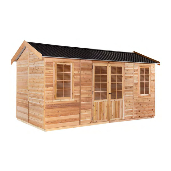
STILLA
ASSEMBLY INSTRUCTIONS
'Alpine' 16x8
S3094
Every part needed to construct your shed is included inside the pack; cedar
panels, doors, windows, hardware kits & roof sheeting. Please ensure you fully
unpack all the parts & check against the parts checklist before contacting
customer service about anything you believe may be missing. Thank-you!
Advertisement

Subscribe to Our Youtube Channel
Related Manuals for STILLA Alpine


Summary of Contents for STILLA Alpine
- Page 1 STILLA ASSEMBLY INSTRUCTIONS ‘Alpine’ 16x8 S3094 Every part needed to construct your shed is included inside the pack; cedar panels, doors, windows, hardware kits & roof sheeting. Please ensure you fully unpack all the parts & check against the parts checklist before contacting...
- Page 2 • Review all instructions; continue to refer to instructions throughout assembly – step by step. Preparing your site • If you are installing your shed on the Stilla heavy duty floor, this can be placed on unlevelled surfaces and levelled up by using the 100x100 stumps provided. P a g e...
- Page 3 23/10/2023 ALPINE 16x8 PARTS CHECKLIST Part Code Checked Part Description Cedar Clad Ply Panel 1200x2020mm Cedar Clad Ply Window Panel 1200x2020mm Cedar Studio Window Assembly (add per additional WP) Cedar Clad Ply Panel 900x2020mm Cedar Clad Ply Panel 480x2020mm Double Colonial Door 710x1885mm...
- Page 4 23/10/2023 Floor Kit – Option Floor Frame – 140x35 Part Code Checked Part Description Floor End Plate 1242x140x35mm Floor Single Joist 1530x140x35mm Floor Double Joist 1530x140x35mm Floor Nog 379x42x35mm Logs 750mm 1798mm x 800mm 598mm x 800mm 1798mm x 706mm 598mm x 706mm Annex Kit –...
- Page 5 23/10/2023 If no floor option was purchased, go to step 2.0 (Wall Assembly) SKIP TO BACK FOR IMAGES TO HELP WITH FLOOR INSTALL STEP 1.0 FLOOR KIT 1.0 – FLOOR KIT (1 of 6 floor frames) PART CODE QTY DESCRIPTION Floor End Plate 1242mm Floor Single Joist 1530mm Double Joist 1530mm...
- Page 6 23/10/2023 STEP 1.1 FLOOR FRAME INSTALLATION The 16x8 floor frame comes in six parts. Install first floor frame in desired position at desired height and fasten to logs once level and square, then join and fasten next frame until all six are joined and secured to logs. 1.1 –...
- Page 7 23/10/2023 STEP 1.2 FLOOR NOG INSTALLATION 1.2 – FLOOR NOG INSTALLATION PART CODE QTY DESCRIPTION Floor Nog 379x42x35mm 65HHS 65mm Hex Head Screws 1.2 – FLOOR NOG INSTALLATION Mark out measurements shown below (centre of nog). Fasten Floor Nogs (FN) in positions shown in diagram below using 1x 65HHS per join.
-
Page 8: Floor Installation
23/10/2023 STEP 1.3 FLOOR INSTALLATION 1.3 – FLOORING INSTALLATION PART CODE QTY DESCRIPTION Floor Board 1798x800mm Floor Board 598x800mm Floor Board 1798x706mm Floor Board 598x706mm 50PS 50mm Philips Screw 1.3 – FLOORING INSTALLATION Fasten floor sheets to floor frame as shown in diagram below using 50PS. Bring Floor sheets in 47mm on two EP sides from the outside of the floor frame and 44mm from the two DJ sides as seen below. - Page 9 STEP 2.0 DOUBLE DOOR WALL PANEL LAYOUT The 16x8 Alpine comes standard with a double door in the non-gable end of the shed with two window panels either side, as seen in the plan below. Follow the steps outlined in the following pages to assemble this plan in the correct order.
-
Page 10: Wall Assembly
23/10/2023 STEP 2.1 WALL ASSEMBLY 2.1 - ASSEMBLY PARTS – WALL ASSEMBLY PART CODE DESCRIPTION 1200mm Window Panel 1200mm Panel 65HHS 65mm Hex head screw 2.1 - ASSEMBLY – WALL ASSEMBLY Screw through 12P into WP (top, centre & bottom) using 3 x 65HHS*. * It helps to have one person adjusting from the outside and one person screwing on the inside. - Page 11 23/10/2023 STEP 2.2 WALL ASSEMBLY 2.2 - ASSEMBLY PARTS – WALL ASSEMBLY PART CODE QTY DESCRIPTION 480mm Front Panel 65HHS 65mm Hex head screw 2.2 - ASSEMBLY – WALL ASSEMBLY Screw through WP into FP (top, centre & bottom) using 3 x 65HHS*. Cedar strip on FWP or FP should be on the door side.
- Page 12 23/10/2023 STEP 2.3 WALL ASSEMBLY 2.3 - ASSEMBLY PARTS – WALL ASSEMBLY PART CODE QTY DESCRIPTION 1200mm Panel 65HHS 65mm Hex head screw 2.3 - ASSEMBLY – WALL ASSEMBLY Screw through 12P into 12P (top, centre & bottom) using 3 x 65HHS*. * It helps to have one person adjusting from the outside and one person screwing on the inside.
- Page 13 23/10/2023 STEP 2.4 WALL ASSEMBLY 2.4 - ASSEMBLY PARTS – WALL ASSEMBLY PART CODE QTY DESCRIPTION 900mm Panel 65HHS 65mm Hex head screw 2.4 - ASSEMBLY – WALL ASSEMBLY Screw through 12P into 9P (top, centre & bottom) using 3 x 65HHS*. * It helps to have one person adjusting from the outside and one person screwing on the inside.
- Page 14 23/10/2023 STEP 2.5 WALL ASSEMBLY 2.5 - ASSEMBLY PARTS – WALL ASSEMBLY PART CODE QTY DESCRIPTION 900mm Panel 65HHS 65mm Hex head screw 2.5 - ASSEMBLY – WALL ASSEMBLY Screw through 9P into 9P (top, centre & bottom) using 3 x 65HHS*. * It helps to have one person adjusting from the outside and one person screwing on the inside.
- Page 15 23/10/2023 STEP 2.6 WALL ASSEMBLY 2.6 - ASSEMBLY PARTS – WALL ASSEMBLY PART CODE QTY DESCRIPTION 1200mm Panel 65HHS 65mm Hex head screw 2.6 - ASSEMBLY – WALL ASSEMBLY Screw through 9P into 12P (top, centre & bottom) using 3 x 65HHS*. * It helps to have one person adjusting from the outside and one person screwing on the inside.
- Page 16 23/10/2023 STEP 2.7 WALL ASSEMBLY 2.7 - ASSEMBLY PARTS – WALL ASSEMBLY PART CODE QTY DESCRIPTION 900mm Panel 65HHS 65mm Hex head screw 2.7 - ASSEMBLY – WALL ASSEMBLY Screw through 12P into 9P (top, centre & bottom) using 3 x 65HHS*. * It helps to have one person adjusting from the outside and one person screwing on the inside.
- Page 17 23/10/2023 STEP 2.8 WALL ASSEMBLY 2.8 - ASSEMBLY PARTS – WALL ASSEMBLY PART CODE QTY DESCRIPTION 900mm Panel 65HHS 65mm Hex head screw 2.8 - ASSEMBLY – WALL ASSEMBLY Screw through 9P into 9P (top, centre & bottom) using 3 x 65HHS*. * It helps to have one person adjusting from the outside and one person screwing on the inside.
- Page 18 23/10/2023 STEP 2.9 WALL ASSEMBLY 2.9 - ASSEMBLY PARTS – WALL ASSEMBLY PART CODE QTY DESCRIPTION 1200mm Panel 65HHS 65mm Hex head screw 2.9 - ASSEMBLY – WALL ASSEMBLY Screw through 12P into 9P (top, centre & bottom) using 3 x 65HHS*. * It helps to have one person adjusting from the outside and one person screwing on the inside.
- Page 19 23/10/2023 STEP 3.0 WALL ASSEMBLY 3.0 - ASSEMBLY PARTS – WALL ASSEMBLY PART CODE QTY DESCRIPTION 1200mm Panel 65HHS 65mm Hex head screw 3.0 - ASSEMBLY – WALL ASSEMBLY Screw through 12P into 12P (top, centre & bottom) using 3 x 65HHS*. * It helps to have one person adjusting from the outside and one person screwing on the inside.
- Page 20 23/10/2023 STEP 3.1 WALL ASSEMBLY 3.1 - ASSEMBLY PARTS – WALL ASSEMBLY PART CODE QTY DESCRIPTION 1200mm Window Panel 65HHS 65mm Hex head screw 3.1 - ASSEMBLY – WALL ASSEMBLY Screw through 12P into WP (top, centre & bottom) using 3 x 65HHS*. * It helps to have one person adjusting from the outside and one person screwing on the inside.
- Page 21 23/10/2023 STEP 3.2 WALL ASSEMBLY 3.2 - ASSEMBLY PARTS – WALL ASSEMBLY PART CODE QTY DESCRIPTION 480mm Front Panel 65HHS 65mm Hex head screw 3.2 - ASSEMBLY – WALL ASSEMBLY Screw through WP into FP (top, centre & bottom) using 3 x 65HHS*. Cedar strip on FP should be on the door side.
- Page 22 23/10/2023 STEP 3.3 DOOR HEAD INSTALL 3.3 - ASSEMBLY PARTS – DOOR HEAD INSTALL PART CODE QTY DESCRIPTION 1440x123x45mm Double Door Head Mending Plate 32PS 32mm Phillips Screw 3.3 - ASSEMBLY – DOOR HEAD INSTALL 1. Mark 75mm either side on top of door head (tongue is on top). 2.
- Page 23 23/10/2023 STEP 3.4 DOOR HEAD INSTALL 3.4 - ASSEMBLY PARTS – DOOR HEAD INSTALL PART CODE QTY DESCRIPTION 65HHS 65mm Hex head screw 3.4 - ASSEMBLY – DOOR HEAD INSTALL Secure Door Head by screwing 1x 65HHS through front panel into bottom of Door Head, as seen below.
- Page 24 23/10/2023 STEP 3.5 DOOR SURROUND INSTALL 3.5 - ASSEMBLY PARTS – DOOR SURROUND INSTALL PART CODE QTY DESCRIPTION DDSS Double Door Surround Set – 2@ 1440mm, 2@ 1870mm (DD option) 40mm Nail 3.5 - ASSEMBLY – DOOR SURROUND INSTALL 1. Nail top 1440mm Door Surround to bottom of door head (flush with back) using 4x 40N. 2.
- Page 25 23/10/2023 STEP 3.6 GABLE ASSEMBLY 3.6 - ASSEMBLY PARTS – GABLE ASSEMBLY (1 OF 2 gables) PART CODE QTY DESCRIPTION 8ft Gable (left and right) 490mm Back Gable Cover Strip 65HHS 65mm Hex head screw 40mm Nail 3.6 - ASSEMBLY – GABLE ASSEMBLY (1 OF 2 gables) Lay left and right gables (G) on a flat surface with the frame facing upwards, as seen below.
- Page 26 23/10/2023 STEP 3.7 GABLE INSTALL 3.7 - ASSEMBLY PARTS –GABLE INSTALL (1 of 2 Gables) PART CODE QTY DESCRIPTION Assembled 8ft Gable 65HHS 65mm Hex head screw 3.7 - ASSEMBLY –GABLE INSTALL (1 of 2 Gables) Carefully place assembled gable on back wall, ensuring groove on gable slots into the tongue on the wall, as seen below.
- Page 27 23/10/2023 STEP 3.8 ROOF SUPPORT BLOCK INSTALL 3.8 - ASSEMBLY PARTS –ROOF SUPPORT BLOCK INSTALL PART CODE QTY DESCRIPTION Roof Support Block 250x70x45 75BS 75mm Batten Screw 3.8 - ASSEMBLY –ROOF SUPPORT BLOCK INSTALL Place Roof Support Block flush with bottom of top gable frames as seen in photo below. Screw to gable frame using 2x 75BS per RSB*.
- Page 28 23/10/2023 STEP 4.0 ROOF FRAME ASSEMBLY 4.0 - ASSEMBLY PARTS – ROOF ASSEMBLY (REPEAT TWICE) PART CODE QTY DESCRIPTION Roof End Plate 1568x70x45mm MREP Middle Roof End Plate 1571x70x45mm Roof Rafter 1195x70x45mm Joining Plate 1145x70x45mm 75BS 75mm Batten Screw 4.0 - ASSEMBLY – ROOF ASSEMBLY (1 of 2 frames) It helps to find a flat, level surface to complete this process on.
- Page 29 23/10/2023 STEP 4.1 ROOF INSULATION INSTALL If you did not purchase this option please skip this step 4.1 - ASSEMBLY PARTS – ROOF INSULATION INSTALL (REPEAT TWICE) PART CODE QTY DESCRIPTION RI (option) Roof Insulation 4800x1300mm 40mm Nail 4.1 - ASSEMBLY – ROOF INSULATION INSTALL (REPEAT WITH SECOND FRAME) It helps to find a flat, level surface to complete this process on.
-
Page 30: Roof Assembly
23/10/2023 STEP 4.2 ROOF ASSEMBLY 4.2 - ASSEMBLY PARTS – ROOF ASSEMBLY (ROOF SHEETS) PART CODE QTY DESCRIPTION 1450mm roof sheet 40RS 40mm Roof screw 25RS 25mm Roof screw 4.2 - ASSEMBLY – ROOF ASSEMBLY (ROOF SHEETS) It helps to find a flat, level surface to complete this process on. Position roof sheets (RS) at either end of roof frame and fasten in place as indicated in diagrams. - Page 31 23/10/2023 STEP 4.3 ROOF ASSEMBLY 4.3 - ASSEMBLY PARTS – ROOF ASSEMBLY (ROOF SHEETS) PART CODE QTY DESCRIPTION 1450mm roof sheet 40RS 40mm Roof screw 25RS 25mm Roof screw 4.3 - ASSEMBLY – ROOF ASSEMBLY (ROOF SHEETS) Complete laying roof sheeting out on frame. Fasten roof sheets to battens in sequence shown.
- Page 32 23/10/2023 STEP 4.4 ROOF ASSEMBLY 4.4 - ASSEMBLY PARTS – ROOF ASSEMBLY PART CODE QTY DESCRIPTION 40RS 40mm Roof screw 25RS 25mm Roof screw 4.4 - ASSEMBLY – ROOF ASSEMBLY Complete screwing roof off at top. 1 x 25RS in pan beside every rib. Once top is complete screw bottom off using 1 x 40RS through every rib.
- Page 33 23/10/2023 STEP 4.5 CHANNEL ASSEMBLY If you purchased the Annex, leave the channel off the side you will be installing your Annex 4.5 - ASSEMBLY PARTS – CHANNEL ASSEMBLY PART CODE QTY DESCRIPTION 12mm self-tapping screw Roof Channel 4.5 - ASSEMBLY – CHANNEL ASSEMBLY Slide Roof channel onto end of roof sheeting overhang.
- Page 34 23/10/2023 STEP 4.6 ROOF END PIECE 4.6 - ASSEMBLY PARTS – RIDGE BEAM BRACKET PART CODE QTY DESCRIPTION Roof End Piece 203x70x30mm 65BS 65 Batten Screws 4.6 - ASSEMBLY – ROOF END PIECES TO GABLES Standing inside shed on ladder, screw roof end pieces to top of gable in required positions using 1x 65BS per piece.
-
Page 35: Roof Installation
23/10/2023 STEP 4.7 ROOF INSTALLATION 4.7 - ASSEMBLY PARTS – ROOF INSTALLATION PART CODE QTY DESCRIPTION Completed roof panels 75BS 75mm Batten Screw 125BS 125mm Batten Screw 4.7 - ASSEMBLY – ROOF INSTALLATION Slide roof frame into position. Ensure point of roof frame is flush with middle of gable as seen below. - Page 36 23/10/2023 STEP 4.8 ROOF INSTALATION 4.8 - ASSEMBLY – ROOF INSTALLATION PART CODE QTY DESCRIPTION 40RS 40mm Roof Screws 25RS 25mm Roof Screws 4.8 – ASSEMBLY – ROOF INSTALLATION Fully fasten down the roof sheeting onto the Roof End Pieces (E) as seen below. Use 2x 25RS to screw into the top E of each side and 2x 40RS to screw into the bottom E of each side.
- Page 37 23/10/2023 STEP 4.9 COLLAR TIE INSTALLATION 4.9- ASSEMBLY PARTS – COLLAR TIE INSTALLATION PART CODE QTY DESCRIPTION Large Collar tie 40RS 40mm Roof Screw 125BS 125mm Batten Screw 4.9 - ASSEMBLY – COLLAR TIE INSTALLATION Holding Collar tie tight and level in position screw through CT into Roof Rafters in predrilled holes, using 6x 40RS per collar tie.
- Page 38 23/10/2023 STEP 5.0 DOUBLE DOOR HINGE ASSEMBLY 5.0 - ASSEMBLY PARTS – DOUBLE DOOR HINGE ASSEMBLY PART CODE DESCRIPTION Butt Hinge Hinge Screw Double Colonial Door 5.0 - ASSEMBLY – DOUBLE DOOR HINGE ASSEMBLY 1. Place door on side and measure out hinge positions as seen below. 2.
- Page 39 23/10/2023 STEP 5.1 DOUBLE DOOR INSTALLATION 5.1 - ASSEMBLY PARTS – DOUBLE DOOR INSTALLATION PART CODE DESCRIPTION Double Colonial Doors Hinge screw 5.1 - ASSEMBLY – DOUBLE DOOR INSTALLATION Mark top door hinge placement on side panel, 105mm from bottom of door head. (so door sits 5mm down from top).
- Page 40 23/10/2023 STEP 5.2 DOUBLE DOOR SEAL INSTALLATION 5.2 - ASSEMBLY PARTS – DOUBLE DOOR SEAL INSTALLATION PART CODE DESCRIPTION Double Door Vertical Seal – 1855x55x20mm 40mm Nail 5.2 - ASSEMBLY – DOUBLE DOOR SEAL INSTALLATION Choose fixed door (generally left hand door). Position flat side of DDS 15mm down from top of door and 40mm in from side and nail to back of fixed door using 8x 40N (as seen below).
- Page 41 23/10/2023 STEP 5.3 BARREL BOLT INSTALL 5.3 – ASSEMBLY PARTS – BARREL BOLT INSTALL PART CODE DESCRIPTION Barrel Bolt Barrel Bolt Screw 5.3 - ASSEMBLY – BARREL BOLT INSTALL Hold Barrel Bolt in position, hard against Door Seal, and fasten to door using 4x BBS per Barrel Bolt (as seen below).
-
Page 42: Door Handle Assembly
23/10/2023 STEP 5.4 DOOR HANDLE ASSEMBLY 5.4 - ASSEMBLY PARTS – DOOR HANDLE ASSEMBLY PART CODE QTY DESCRIPTION T Handle 5.4 - ASSEMBLY – DOOR HANDLE ASSEMBLY 1. Find suitable height for T Handle (generally 1050mm up door). 2. Mark and drill 12mm centre hole in position, 40mm in from door edge. 3. - Page 43 23/10/2023 STEP 5.5 DOOR HANDLE ASSEMBLY 5.5 - ASSEMBLY PARTS – DOOR HANDLE ASSEMBLY PART CODE QTY DESCRIPTION D-Handle Leaver 5.5 - ASSEMBLY – DOOR HANDLE ASSEMBLY Holding door in closed position, flush with other door - slide leaver onto T Handle and tighten using a 4mm alan key once hitting Seal on fixed door.
- Page 44 23/10/2023 STEP 5.6 WINDOW ASSEMBLY INSTALLATION 5.6 - ASSEMBLY PARTS – WINDOW ASSEMBLY INSTALLATION PART CODE QTY DESCRIPTION Studio Window Assembly 32PS 32mm Phillips screw 5.6 - ASSEMBLY – WINDOW ASSEMBLY INSTALLATION Fit Window Assembly into hole in Window Panel*. Ensuring the window frame is square, fasten to Window Panel by screwing through perimeter of Window Panel hole into SWA**.
- Page 45 23/10/2023 STEP 5.7 IINTERNAL WINDOW STRIP ASSEMBLY 5.7 - ASSEMBLY PARTS – INTERNAL WINDOW STRIP ASSEMBLY PART CODE QTY DESCRIPTION SIWS Studio Internal Window Strip Set- 2@ 770mm, 2@ 1240mm 40mm Nail 5.7 - ASSEMBLY – INTERNAL WINDOW STRIP ASSEMBLY 1.
- Page 46 23/10/2023 STEP 6.0 CORNER POST ASSEMBLY 6.0 - ASSEMBLY PARTS – CORNER POST ASSEMBLY PART CODE QTY DESCRIPTION 2015mm Corner Post 40mm Nail 6.0 - ASSEMBLY – CORNER POST ASSEMBLY Hold corner post (CP) in position, nail through CP into wall stud using 6x 40N evenly spaced along CP.
- Page 47 23/10/2023 STEP 6.1 COVER STRIP ASSEMBLY 6.1 - ASSEMBLY PARTS – COVER STRIP ASSEMBLY PART CODE QTY DESCRIPTION 2015mm Cover Strip 40mm Nail 6.1 - ASSEMBLY – COVER STRIP ASSEMBLY Hold cover strips (CS) over joins in walls and beside door/s, nail through CS into wall panel using 6x 40N evenly spaced per CS.
- Page 48 23/10/2023 STEP 6.2 FASCIA ASSEMBLY 6.2 - ASSEMBLY PARTS – FASCIA ASSEMBLY PART CODE QTY DESCRIPTION 8ft Studio Fascias – 140x20 40mm Nail 6.2 - ASSEMBLY – FASCIA ASSEMBLY Hold fascias in position, parallel with Ends and join evenly at top. Nail 2x 40N through fascia into End pieces to fasten.
- Page 49 23/10/2023 STEP 6.4 EXTERNAL FIXED WINDOW STRIP ASSEMBLY If you did not purchase a fixed window panel, please skip this step. 6.4 - ASSEMBLY PARTS – COVER STRIP ASSEMBLY PART CODE QTY DESCRIPTION 2015mm Cover Strip (per fixed window) 40mm Nail (per fixed window) 6.4 - ASSEMBLY –...
- Page 50 23/10/2023 STEP 6.5 6.5 - ASSEMBLY PARTS – FIXING TO BASE PART CODE QTY DESCRIPTION 65HHS 65mm Hex Head Screw 6.5 - ASSEMBLY – FIXING TO BASE Once shed is in desired position and doors are sitting evenly you can now fix your shed to the base.
- Page 51 23/10/2023 STEP 7.0 ANNEX FRAME ASSEMBLY If you did not purchase this option please skip this step 7.0 - ASSEMBLY PARTS – ANNEX FRAME PART CODE QTY DESCRIPTION Veranda Beam 2560x70x45mm Veranda Beam Joiner 700x70x45mm Veranda Outer Beam 2560x140x35mm VOBJ Veranda Outer Beam Joiner 700x140x35mm Veranda Rafter 1320x70x45mm 65BS...
- Page 52 23/10/2023 51 | P a g e...
- Page 53 23/10/2023 STEP 7.1 ANNEX ROOF 7.1 - ASSEMBLY PARTS – ANNEX ROOF PART CODE QTY DESCRIPTION 1450mm Veranda Roof Sheet 40RS 40mm roof screw 25RS 25mm roof screw 7.1 - ASSEMBLY – ANNEX ROOF Place assembled veranda on a flat, level surface to fasten roofing. Position veranda roof sheets (VRS) at either end of roof frame and fasten in place as indicated in diagrams.
- Page 54 23/10/2023 STEP 7.2 ANNEX ROOF 7.2 - ASSEMBLY PARTS – ANNEX ROOF PART CODE QTY DESCRIPTION 1450mm veranda roof sheet 40RS 40mm Roof screw 25RS 25mm Roof screw 7.2 - ASSEMBLY – ANNEX ROOF Complete laying roof sheeting out on frame. Fasten roof sheets to beams in sequence shown.
- Page 55 23/10/2023 STEP 7.3 ANNEX ROOF 7.3 - ASSEMBLY PARTS – ANNEX ROOF PART CODE QTY DESCRIPTION 40RS 40mm Roof screw 25RS 25mm Roof screw 7.3 - ASSEMBLY – ANNEX ROOF Complete screwing roof off at top. 1 x 25RS in pan beside every rib. Once top is complete screw bottom off using 1 x 40RS through every rib.
- Page 56 23/10/2023 55 | P a g e...
- Page 57 23/10/2023 STEP 7.5 ANNEX ROOF INSTALATION 7.5 - ASSEMBLY PARTS – ANNEX ROOF INSTALLATION PART CODE QTY DESCRIPTION Veranda Posts 2400x90x90mm 100BS 100mm batten screw 200PB 200mm M12 Post Bolt M12 Washer 7.5 - ASSEMBLY – ANNEX ROOF INSTALLATION 1. Using at least 3 people, butt the veranda roof hard up under shed roof as seen below. Support front of veranda roof while fastening through frame into shed wall studs, using 5x 100BS.
- Page 58 23/10/2023 STEP 7.6 ANNEX FASCIA 7.6 - ASSEMBLY PARTS – ANNEX FASCIA PART CODE QTY DESCRIPTION Veranda fascia 1350x140x20 block cedar 40mm nail 7.6 - ASSEMBLY – ANNEX FASCIA Once fascia’s are on shed, trim annex fascia to butt in and finish correctly. Nail through fascia using 4 x 40N per fascia.
- Page 59 23/10/2023 IMAGES TO HELP WITH INSTALLATION FLOOR 58 | P a g e...
- Page 60 23/10/2023 59 | P a g e...
- Page 61 23/10/2023 60 | P a g e...
- Page 62 23/10/2023 61 | P a g e...
- Page 63 23/10/2023 62 | P a g e...
- Page 64 23/10/2023 63 | P a g e...
- Page 65 23/10/2023 64 | P a g e...
- Page 66 23/10/2023 65 | P a g e...
-
Page 67: Product Maintenance
23/10/2023 TO REGISTER YOUR WARRANTY Thank-you for purchasing a STILLA product. To register your 10 year product warranty, please go to www.stilla.com.au/warranty and complete the online form. We recommend that you complete this step once you have finished installing your product. - Page 68 23/10/2023 SHOW US YOUR SHED We would love to see a photo of your STILLA product installed in your backyard. Please upload this image when completing the warranty registration. Alternatively, you can send the photos by email to sales@stilla.com.au. If you require any assistance, please feel free to call or email.
Need help?
Do you have a question about the Alpine and is the answer not in the manual?
Questions and answers