
Subscribe to Our Youtube Channel
Related Manuals for LD AMP 205


Summary of Contents for LD AMP 205
- Page 1 USER'S MANUAL ENGLISH AMP 205 2-CHANNEL MINI INSTALLATION POWER AMPLIFIER 2X50 W @ 4 OHM LDAMP205...
-
Page 2: Table Of Contents
CONTENTS ENGLISH ABOUT THIS MANUAL INTENDED USE DEFINITIONS AND SYMBOL EXPLANATIONS SAFETY INSTRUCTIONS NOTES FOR INDOOR INSTALLATION UNITS PACKAGING CONTENT INTRODUCTION CONNECTIONS, OPERATING AND DISPLAY ELEMENTS 8 TERMINAL BLOCK CONNECTIONS CONNECTION EXAMPLE UNDER / ON-TABLE MOUNTING CARE, MAINTENANCE AND REPAIR DIMENSIONS TECHNICAL DATA DISPOSAL... -
Page 3: About This Manual
ENGLISH YOU HAVE MADE THE RIGHT CHOICE! We have designed this product to work reliably for many years. This is what LD Systems stands for with its name and its many years of experience as a manufacturer of high-quality audio products. -
Page 4: Safety Instructions
This symbol identifies hazards that can cause electric shock. This symbol identifies hazardous areas or hazardous situations. This symbol indicates hazards caused by hot surfaces. This symbol indicates dangers due to high volume levels. This symbol indicates additional information on the operation of the product. This symbol denotes a device that does not contain any user-serviceable parts. - Page 5 ATTENTION: 1. Do not operate the unit if it has been exposed to large temperature fluctuations (for example, after transport). Moisture and condensation can damage the device. Switch on the device only when it has reached room temperature. 2. Make sure that the voltage and frequency of the mains supply correspond to the values indicated on the unit.
-
Page 6: Notes For Indoor Installation Units
ATTENTION: 1. Do not install or operate the appliance near any radiators, heat registers, stoves or other heat sources. Ensure that the device is always installed in such a way that it is sufficiently cooled and cannot overheat. 2. Do not place ignition sources such as burning candles near the appliance. 3. -
Page 7: Packaging Content
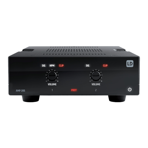
• 1 x mounting set for under- or on-table mounting • User manual INTRODUCTION The LD AMP205 is a professional 2-channel mini installation amplifier. Part of the TICA® series, it combines a compact size, passive cooling, and high efficiency – ideal for a diverse range of audio installation applications. -
Page 8: Connections, Operating And Display Elements
CONNECTIONS, OPERATING AND DISPLAY ELEMENTS POWER IN Terminal block connection for the device‘s power supply. To avoid damage to the device, please use only the original power supply (power supply included). STRAIN RELIEF Use the strain relief for the flexible cable of the power supply unit to protect the device‘s power terminal block connector and the power supply terminal block from damage and to prevent the terminal block from being pulled out unintentionally. - Page 9 SETTINGS DIP switch 1 AUTO STB: Move the switch to the ON position to activate the unit‘s automatic standby function. If the standby function is activated, the amplifier is automatically set to standby mode if no audio signal is detected for about 20 minutes. In this way, power consumption is sensibly reduced.
- Page 10 POWER SYMBOL The power symbol lights up white when the installation amplifier is ready for operation. In standby mode, the symbol lights up red. VOLUME 1 / 2 One level control each for channels 1 and 2. Turning to the right increases the volume, turning to the left decreases it.
-
Page 11: Terminal Block Connections
TERMINAL BLOCK CONNECTIONS CONNECTIONS LINE IN 1 / 2 CONNECTIONS STANDBY balanced momentary switch unbalanced CONNECTIONS VCA 1 / 2 Volume VOLUME potentiometer 10 kΩ, linear Ground CONNECTIONS OUT 1 / 2 / HPM BEWARE: When wiring terminal blocks, please observe the correct assignment of the poles/terminals. The manufacturer accepts no liability for damage caused by faulty wiring! -
Page 12: Connection Example
CONNECTION EXAMPLE ON/STANDBY VOLUME... -
Page 13: Under / On-Table Mounting
UNDER / ON-TABLE MOUNTING There are two recesses on the top and bottom of the enclosure, each with two M4 threaded holes, for mounting underneath or on top of the table. Screw the two enclosed mounting plates to the top or bottom side using the enclosed M4 countersunk screws. Now the amplifier can be fixed in the desired position (see illustration, mounting screws not included in delivery). -
Page 14: Dimensions
1. Housing surfaces must be cleaned with a clean, damp cloth. Make sure that no moisture can penetrate the device. 2. Air inlets and outlets must be regularly cleaned of dust and dirt. If compressed air is used, make sure that damage to the device is prevented (e.g. fans must be blocked in this case). 3. -
Page 15: Technical Data
TECHNICAL DATA Item number LDAMP205 Product type Installation power amplifier Line inputs Line input connectors Balanced line inputs, pitch 3.81mm terminal block (3-pin) Line outputs Powered outputs 2 with output mode selector (Stereo / Parallel / High Power Mode) Cooling system Convection cooling Priority levels Input Section... -
Page 16: Disposal
Power Supply Type External SMPS Voltage Range 100 VAC – 240 VAC (+-10%), 50–60 Hz Mains fuse None Secondary Voltage 24 V DC Secondary Current 3.5 A Secondary Connector Terminal Block 5.08mm 2-pole Primary Connector IEC Jack Safety Class Class 3 Max power consumption 115 W (sine 1 kHz with 2 x 4 Ohm load) Idle power consumption... -
Page 17: Manufacturer's Declarations
MANUFACTURER’S DECLARATIONS MANUFACTURER’S WARRANTY & LIMITATION OF LIABILITY Adam Hall GmbH, Adam-Hall-Str. 1, D-61267 Neu Anspach / E-Mail Info@adamhall.com / +49 (0)6081 / 9419-0. Our current warranty conditions and limitation of liability can be found at: https://cdn-shop.adamhall.com/media/pdf/MANUFACTURERS-DECLARATIONS_LD_SYSTEMS.pdf . In case of service, please contact your sales partner. UKCA-CONFORMITY Hereby, Adam Hall Ltd. - Page 18 LD-SYSTEMS.COM Adam Hall GmbH | Adam-Hall-Str. 1 | 61267 Neu-Anspach | Germany Phone: +49 6081 9419-0 | adamhall.com Adam Hall Ltd. | The Seedbed Business Centre | SS3 9QY Essex | UK REV: 01...
Need help?
Do you have a question about the AMP 205 and is the answer not in the manual?
Questions and answers