
Related Manuals for Pfaff Industrial 918 U


Summary of Contents for Pfaff Industrial 918 U
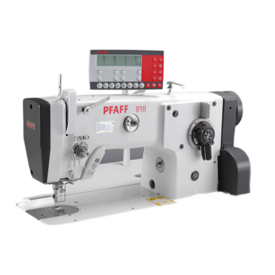
- Page 1 918 U INSTRUCTION MANUAL 938 U This instruction manual applies to machines from the serial number 8 300 001 and software version 0435/006 onwards. 296-12-19 337/002 Instruction Manual engl. 06.18...
- Page 2 This instruction manual applies to all models and subclasses listed in chapter 3 Technical Data. The adjustment manual for the machine can be downloaded at no charge under www.pfaff-industrial.de/de/service-support/downloads/technical. As an alternative to the Internet download, the adjustment manual can also be ordered under order no.
-
Page 3: Table Of Contents
Adjusting levers for zigzag stitch and needle position ............16 Reverse-feed key / stitch length adjusting wheel ..............16 Adjusting wheel for multi-stitches and zigzag stitches (only on the PFAFF 918 U and 938 U) .................. 17 Lever to raise the sewing foot ..................... 17 Pedal ............................ 18 Adjusting lever for under-edge trimmer -771/05 .............. - Page 4 Setting the zigzag stitch and needle position ............... 33 Setting the stitch length ....................... 33 Setting multi-stitches and zigzag stitches (on the 918 U and 938 U with a flange motor) ..............34 .08.01 Change-over from zigzag stitch to multi-stitch ..............34 .08.02...
-
Page 5: Safety
Safety Safety Directives The machine was built in compliance with the European regulations specified in the declaration of conformity and declaration of incorporation. As a supplement to this instruction manual, please also observe the generally applicable, legal and other regulations and legislation – also in the country of use – and the valid environmental protection regulations! Always comply with the locally applicable regulations of the professional associations and other supervisory authorities! General safety instructions... -
Page 6: Safety Symbols
Safety Safety symbols Hazard point! Special points of attention. Risk of injury to operating personnel or technical staff! Electric voltage! Danger to operating personnel or technical staff Danger of hands being crushed! Danger to operating personnel or technical staff Caution! Do not operate without finger guard and safety covers! Turn off the main switch before threading, changing the bobbin or needle, cleaning, etc.! -
Page 7: Operating Personnel And Technical Staff
Safety Operating personnel and technical staff Operating personnel .05.01 Operating personnel are persons responsible for equipping, operating and cleaning the machine and for fault clearance in the sewing area. The operating personnel are obligated to comply with the following points: O The safety instructions provided in the instruction manual must be followed for all work! O Any work method jeopardising machine safety must be refrained from! O Tight-fitting clothing must be worn. -
Page 8: Danger Warnings
Safety Danger warnings A work area of 1 m must be kept free in front of and behind the machine to en- sure unobstructed access at all times. Do not reach into the needle range during the sewing operation! Risk of injury from the needle! Do not allow any objects to be placed on the table during the adjustment work! The objects could become jammed or be slung away! Risk of injury from parts flying around! -
Page 9: Proper Use
Proper Use The PFAFF 918 is a high-speed zigzag seamer with a drop feed and large hook. The PFAFF 918 U is a high-speed zigzag seamer with a drop feed, large hook and mechanical change-over from zigzag to 3-stitch zigzag. -
Page 10: Technical Data
Technical Data Technical Data PFAFF 918, 938 Stitch type: ....................304 (zigzag lockstitch) Needle system: ........................438 Needle size in 1/100 mm: Model A: ......................... 60 - 70 Model B: ........................80 - 100 Clearance beneath the sewing foot: .................7 mm Passage width: ......................260 mm Clearance height: ......................130 mm Bed plate dimensions: .................. -
Page 11: Pfaff 918 U, 938 U
Width: ......................approx. 180 mm Height (above table): ..................approx. 300 mm Max. stitch length: ......................2.5 mm Max zigzag stitch width PFAFF 918 U: ....................... 10.0 mm PFAFF 938 U: .........................6.0 mm Max. stitch count: For a needle bar stroke of 33 mm: ..............4500 stitches/min Connection data: Operating voltage: ................ -
Page 12: Disposal Of The Machine
Disposal of the Machine Disposal of the Machine O It is up to the customer to dispose of the machine properly. O The materials used for the machine include steel, aluminium, brass and various plastics. The electrical equipment consists of plastics and copper. O The machine must be disposed of in accordance with the locally valid environmental protection regulations, with a specialised company being contracted if necessary. -
Page 13: Transport, Packaging And Storage
Transport, Packaging and Storage Transport, Packaging and Storage Transport to the customer's premises All machines are completely packed for delivery. Transport within the customer's premises The manufacturer assumes no liability for transport within the customer's premises or to the individual usage sites. Please ensure that the machines are only transported in a vertical position. -
Page 14: Work Symbols
Work Symbols Work Symbols Activities to be performed or important information in this instruction manual are empha- sised by symbols. The symbols used have the following meaning: Note, information Cleaning, care Lubrication Maintenance, repairs, adjustment, service work (only to be carried out by technical staff) -
Page 15: Operating Controls
Operating Controls Operating Controls Main switch Before switching on the machine, raise the take-up lever as far as possible. Turning the main switch 1 switches the machine on and off. Fig. 7 - 01 Keys on the machine head (only in machines with a fl... -
Page 16: Adjusting Levers For Zigzag Stitch And Needle Position
Operating Controls Adjusting levers for zigzag stitch and needle position O The adjusting lever 1 is used to adjust the zigzag stitch width. O The locking lever 2 must be pressed against the adjusting lever 1 to adjust the adjusting lever. The set zigzag stitch width is shown on the scale 3. -
Page 17: Adjusting Wheel For Multi-Stitches And Zigzag Stitches (Only On The Pfaff 918 U And 938 U)
Operating Controls Adjusting wheel for multi-stitches and zigzag stitches (only on the PFAFF 918 U and 938 U) Before starting to sew, make sure that the adjusting wheel 1 is engaged! Only make the change-over when the machine is at a standstill! Danger of... -
Page 18: Pedal
Operating Controls Pedal O With the main switch turned on = Neutral position +1 = Sewing -1 = Raise sewing foot (in machines with automatic presser foot lift -910/..) -2 = Trim thread (in machines with thread trimmer -900/..) Fig. 7 - 07 Adjusting lever for under-edge trimmer -771/05 O The under-edge trimmer is switched on and the knife stroke is set by pulling and... -
Page 19: Set-Up And Initial Start-Up
Set-up and Initial Start-up Set-up and Initial Start-up The machine may only be set up and started up by qualified personnel! All of the relevant safety regulations must always be complied with in this process! If the machine was delivered without a table, then the stand and the table top provided must safely support the weight of the machine and its motor. -
Page 20: Inserting The Sewing Machine Into The Stand
Set-up and Initial Start-up Inserting the sewing machine into the stand .01.02 Fig. 8 - 02 O The hinge 1 is screwed to the sewing head base plate. O Insert the sewing machine into the table top. O Insert the sewing head support 2 into the table top hole. Do not operate the machine without the support 2! Risk of damage due to the top-heavy sewing head! Machine can tip over backwards when moving it! -
Page 21: Assembling The Flange Motor
Set-up and Initial Start-up Assembling the flange motor .01.03 Fig. 8 - 03 O Loosen the screws 1 and pull the toothed belt wheel 2 off the motor shaft 3. O Screw the bearing plate 4 onto the motor 5 with the screws 6, as shown in Fig. 8-04. O Slide the toothed belt wheel 2 onto the motor shaft 3 and tighten with the screws 1. -
Page 22: Mounting The Machine Cover
Set-up and Initial Start-up Mounting the machine cover .01.05 O Slide the left and right belt guard halves with their slots behind the heads of the screws 1 and 2. O Screw the screw 3 with the spacing bush 4 into the threaded hole 5. O Align the belt guard making sure that the lug 6 is behind the slot 7 and in front of the spacing bush 4. -
Page 23: Mounting The Start Inhibitor
Set-up and Initial Start-up Mounting the start inhibitor .01.07 Fig. 8 - 07 O For machines delivered without a table, the plate 1 included in the accessories must be mounted underneath the table top in such a way that the switching plate 2 lays on the plate 1 when the sewing head is tilted upright. -
Page 24: Connecting The Plug-In Connections And Ground Cable
Set-up and Initial Start-up Connecting the plug-in connections and ground cable Fig. 8 - 08 O Insert all plugs on the control box 2 in accordance with their designation. O Insert the "motor" into the bushing E and the bushing M. Caution Inserting the plug incorrectly can damage the control unit! O Attach the following ground cables in order to discharge static electricity... -
Page 25: Assembling The Reel Stand
Set-up and Initial Start-up Assembling the reel stand O Assemble the reel stand as shown in the adjacent illustration. O Then insert the stand into the hole in the table top and secure it with the enclosed nuts. Fig. 8 -09... -
Page 26: Initial Start-Up
Set-up and Initial Start-up Initial start-up Fig. 8 - 10 Fig. 8 - 11 O Remove the plug 1 of the oil reservoir 2 before the initial start-up. O Remove the screw 3 (Fig. 8 -11) before the initial start-up and fill up the oil to the mark (sight glass on the front of the machine), see chapter 10.04 Oiling the zigzag drive. -
Page 27: Switching The Machine On / Off
Set-up and Initial Start-up Switching the machine on / off O Switch the machine on (see chapter 7.01 Main switch). Machine drive home position O See chapter 4.4 of the drive service manual... -
Page 28: Set-Up
Set-up Set-up Observe and comply with all regulations and instructions in this instruction manual. Pay particular attention to all safety regulations! All set-up work may only be carried out by appropriately instructed personnel. Disconnect the machine from the electricity mains for all set-up work by operating the main switch or by removing the mains plug! Inserting the needle Switch off the machine! -
Page 29: Winding The Bobbin Thread / Adjusting The Bobbin Thread Tension
Set-up Winding the bobbin thread / adjusting the bobbin thread tension Fig. 9 - 02 O Fit the empty bobbin 1 onto the bobbin winder spindle 2 with the rest thread chamber on the outside. O Thread in the thread as shown in Fig. 9-02 and wind it round the bobbin 1 a few times in an anti-clockwise direction. -
Page 30: Removing / Inserting The Bobbin Case
Set-up Removing / inserting the bobbin case Switch off the machine! Risk of injury due to accidental machine start-up! Removing the bobbin case: O Tilt the machine backwards. O Raise the lever 1 and remove the bobbin case 2. Inserting the bobbin case: O Press the bobbin case 2 until you feel it snap into the bobbin case base. -
Page 31: Pfaff 938 And 938 U With Thread Trimmer
When the thread is drawn off, the bobbin 1 must turn in the direction shown by the arrow. Fig. 9 - 05 PFAFF 918 and 918 U .04.03 O Pass the thread through the slot under the spring as shown in the adjacent illustration. -
Page 32: Threading The Needle Thread / Adjusting The Needle Thread Tension
Set-up Threading the needle thread / adjusting the needle thread tension Fig. 9 - 07 Switch off the machine! Risk of injury due to accidental machine start-up! O Thread the needle thread as shown in Fig. 9-07. Please ensure that the needle is thread- ed from the front. -
Page 33: Setting The Zigzag Stitch And Needle Position
Set-up Setting the zigzag stitch and needle position O Set the zigzag stitch width by turning the zigzag stitch adjusting lever 1. O Press against the zigzag stitch adjusting lever 1 to adjust the locking lever 2. O The setting is shown on the scale 3. O Set the needle position by turning the needle position adjusting lever 4 L = Needle position on the left... -
Page 34: Setting Multi-Stitches And Zigzag Stitches (On The 918 U And 938 U With A Flange Motor)
Set-up Setting multi-stitches and zigzag stitches (on the 918 U and 938 U with a flange motor) Change-over from zigzag stitch to multi-stitch .08.01 Before starting to sew, make sure that the adjusting wheel 1 is engaged! Only make the... -
Page 35: Setting Multi-Stitches And Zigzag Stitches (On The 918 U And 938 U With An External Motor)
Set-up Setting multi-stitches and zigzag stitches (on the 918 U and 938 U with an external motor) Change-over from zigzag stitch to multi-stitch .09.01 Before starting to sew, make sure that the adjusting wheel 1 is engaged! Only make the... -
Page 36: Maintenance And Care
Maintenance and Care Maintenance and Care Maintenance intervals Cleaning ............daily, several times if in continuous operation Check the oil level (hook oil reservoir) ..............annually Check the oil level (zigzag eccentric lubrication) ........daily, before start-up Check/set the air pressure ..............daily, before start-up Cleaning the maintenance unit air filter ............... -
Page 37: Oiling The Hook
Maintenance and Care Oiling the hook Fig. 10 - 03 Fig. 10 - 02 Switch off the machine! Risk of injury due to accidental machine start-up! Only use oil with a centre viscosity of 22.0 mm²/s at 40 °C and a density of 0.865 g/cm³... -
Page 38: Oiling The Zigzag Drive
Maintenance and Care Oiling the zigzag drive Fig. 10 - 04 Fig. 10 - 05 Switch off the machine! Risk of injury due to accidental machine start-up! Only use oil with a centre viscosity of 68.0 mm²/s at 40 °C and a density of 0.881 g/cm³... -
Page 39: Checking / Setting The Air Pressure
Maintenance and Care Checking / setting the air pressure O Check the air pressure on the manometer 1 before every start-up. O The manometer 1 must show a pressure of 6 bar. O Adjust this value if needed. O To do this, pull up the button 2 and turn it so that the manometer 1 shows a pressure of 6 bar. -
Page 40: Parameter Settings
Maintenance and Care Parameter settings Parameter settings are described in the separate parameter list for the drive and may only be changed by qualified technicians. - Page 41 Table top cutout Table Top Table top cutout...
- Page 42 Table top cutout Table top assembly 102,5 102,5 83,5 53,5 Kabelkanal / cable duct 20 x 20 x 250 Erdung / grounding...
-
Page 43: Wearing Parts
Wearing Parts Wearing Parts This list shows the most important wearing parts. A detailed parts list for the complete machine can be downloaded at www.pfaff-industrial.de/pfaff/de/service-support/downloads/technical. As an alternative to the Internet download, the parts list can also be requested as a hard copy under order no. 296-12-19 337. 91-100 296-25 (3x) 91-701 179-15 11-108 174-25... - Page 44 Wearing Parts PFAFF 938 91-265 225-91 91-265 227-05 (3x) 91-167 595-05 91-174 507-05 91-168 144-05 91-140 945-05 91-167 598-41 11-174 912-15 (2x) 91-175 690-05 91-265 227-05 (3x) 91-009 026-05 91-002 134-05 91-000 250-15 91-167 597-91 91-000 390-05 99-137 151-45 91-171 049-05 91-171 042-05 95-774 464-25 91-700 996-15...
- Page 45 Notes...
- Page 46 PFAFF Industriesysteme und Maschinen GmbH Hans-Geiger-Str. 12 - IG Nord D-67661 Kaiserslautern Tel.: +49 - 6301 3205 - 0 Fax: +49 - 6301 3205 - 1386 E-mail: info@pfaff-industrial.com Gedruckt in der BRD / Printed in Germany...
Need help?
Do you have a question about the 918 U and is the answer not in the manual?
Questions and answers