
Related Manuals for Pfaff Industrial 1244


Summary of Contents for Pfaff Industrial 1244
- Page 1 ® Industrial 1243 1244 INSTRUCTION MANUAL This instruction manual applies to machines from the following serial numbers onwards: # 7 250 050 296-12-18 243/002 Betriebsanleitung engl. 07.14...
- Page 2 This Instruction Manual is valid for all models and subclasses listed in the ". chapter "Specifications The adjustment manual for the machines can be downloaded free of charge from the internet address. www.pfaff-industrial.com/pfaff/de/service/downloads As an alternative to the internet download the adjustment manual can also be ordered in book form under part no.
-
Page 3: Table Of Contents
Models and Subclasses..................... 3 - 2 Max. number of stitches/min-1 for the PFAFF 1243 ........... 3 - 2 Max. number of stitches/min-1 for the PFAFF 1244 ..........3 - 2 Disposal of Machine ....................4 - 1 Transportation, packing and storage ............... 5 - 1 Transportation to customer‘s premises .............. - Page 4 Threading needle thread/adjusting needle thread tension ( on the PFAFF 1243 ) ....9 - 5 Threading needle thread/adjusting needle thread tension ( on the PFAFF 1244 ) ....9 - 6 Adjusting the stitch counter for the bobbin thread control......... 9 - 7 Care and maintenance....................
-
Page 5: Safety
Safety Safety Regulations This machine has been made according to the European regulations indicated in the conformity and manufacturer’s declarations. In addition to this instruction manual, please also observe all generally accepted statutory and other legal requirements, including those of the user’s country, and the valid pollution control regulations! The locally valid regulations of the social insurance institution responsible for occupational accidents, or other supervisory authorities, must be strictly adhered to! -
Page 6: Safety Symbols
Safety Safety symbols Danger! Special points to observe Danger of injury to operating or technical staff! Caution Do not operate without finger guard and safety devices. Before threading, changing bobbin and needle, cleaning etc. switch off main switch. Important notes for the user This instruction manual is part of the equipment of the machine and must be available to the operating staff at all times. - Page 7 Safety Notes for operating and technical staff Operating staff .05.01 Operating staff are the persons responsible for setting up, operating and cleaning the mach- ine and for removing any disturbances in the sewing area. The operating staff are obliged to observe the following points, and must: always observe the notes on safety in this instruction manual! avoid using any working methods which adversely effect the safety of the machine! avoid wearing loose-fitting clothing or jewelry such as necklaces or rings!
-
Page 8: Danger Warnings
Safety Danger warnings 1 m must be kept free both in front of and behind the A working area of machine, so that easy access is possible at all times. Never put your hands or fingers in the sewing area during sewing! Danger of injury by the needle! While setting or adjusting the machine do not leave any objects on the table nor in the needle plate area! Objects may be trapped or flung out of the machine! -
Page 9: Proper Use
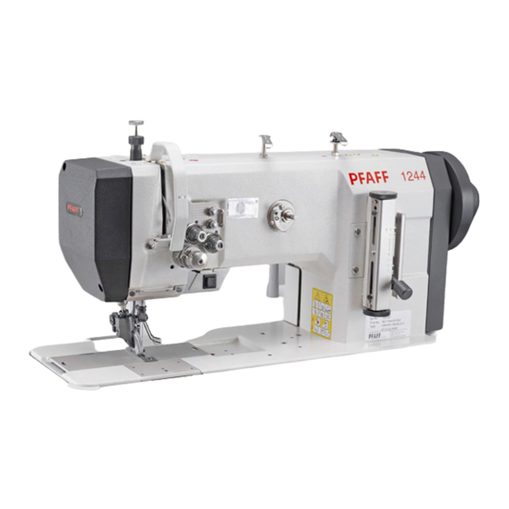
PFAFF 1243 is a single-needle lockstitch sewing machine with roller presser and large vertical sewing hook. PFAFF 1244 is a two-needle lockstitch sewing machine with roller presser and large vertical sewing hook. The machines are used for producing lockstitch seams in the textile and leather industries. -
Page 10: Specification
( Noise measurement in accordance with DIN 45 635-48-A-1,ISO 11204, ISO 3744, ISO 4871 ) PFAFF 1243 at a speed of 1500 spm.: : ............... L = 79 dB(A) PFAFF 1244 at a speed of 1400 spm.:............L = 79 dB(A) Subject to technical alterations Or comparable sizes of other thread types... -
Page 11: Models And Subclasses
-911/97 ..... Automatic presser-foot lifter with backtacking mechanism Max. speeds of the PFAFF 1243 Model Type of machine Max.speed (r.p.m.) 2100 PFAFF 1243 Max. speeds of the PFAFF 1244 Type of machine Model Max.speed (r.p.m.) 2000 PFAFF 1244 3 - 2... -
Page 12: Disposal Of Machine
Disposal of Machine Disposal of Machine Proper disposal of the machine is the responsibility of the customer. The materials used for the machine are steel, aluminium, brass and various plastic materials. The electrical equipment comprises plastic materials and copper. The machine is to be disposed of according to the locally valid pollution control regula- tions;... -
Page 13: Transportation, Packing And Storage
Transportation, packing and storage Transportation, packing and storage Transportation to customer's premises The machines are delivered completely packed. Transportation inside the customer's premises The manufacturer cannot be made liable for transportation inside the customer's premises nor to other operating locations. It must be ensured that the machines are only transported in an upright position. -
Page 14: Explanation Of Symbols
Explanation of symbols Explanation of symbols In this instruction manual, work to be carried out or important information is accentuated by symbols. These symbols have the following meanings: Note, information Cleaning, care Lubrication Maintenance, repairs, adjustment, service work (only to be carried out by technical staff) 6 - 1... -
Page 15: Controls
Controls Controls On/off switch The power supply to the machine is switched on or off by turning switch 1. The illustrated on/off switch is fitted to machines with motors. If other motors are sed, a different switch may be fitted. Fig. -
Page 16: Pedal (On Machines With Subclass -911/97)
Controls Pedal (on machines with subclass -911/97 = Neutral position +1 = Sewing -1 = Raise presser foot -2 = Thread trimming (on machines with thread trimmer) Fig. 7 - 03 Knee lever (on machines without subclass -911/97) The presesr foot is raised by pressing knee lever 1. -
Page 17: Key On Machine Head (On Machines With Subclass -911/97)
Controls Key on machine head (on machines with subclass -911/97) If key 1 is pressed during sewing, the machine will switch to reverse sewing. Fig. 7 - 06 Lever for lifting the roller presser The roller presser is lifted by raising lever 1. -
Page 18: Feed Regulator/Reverse Sewing
Controls Feed regulator/reverse sewing The stitch length is adjusted by turning the knurled nut on lever 1. G To reverse the sewing direction press lever 1 fully upwards. Fig. 7 - 07 Feed regulator (on machines with subclass -911/97) Turn knurled screw 1 to adjust the stitch length for sewing forwards. -
Page 19: Control Panel ( On Machines With Attached Motor )
Controls Control panel (only on machines with attached motor) The description can be found in the separate instruction manual for the control panel. 7 - 5... -
Page 20: Installation And Commissioning
Installation and commissioning Installation and commissioning The machine must only be mounted and commissioned by qualified personnel! All relevant safety regulations are to be observed! If the machine is delivered without a table, it must be ensured that the frame and the table top which you intend to use can hold the weight of the machine and the motor. -
Page 21: Assembling The Motor (Only On Machines With Motor)
Installation and commissioning Assembling the motor .01.02 (only on machines with motor) 109-001 Fig. 8 - 02 Assemble motor mounting 1, motor 2, belt guard support 3 and belt pulley 4 as shown in Fig. 8-02. Tightening the V-belt .01.03 Fit the V-belt. -
Page 22: Mounting The Bottom V-Belt Guard
Installation and commissioning Mounting the bottom V-belt guard .01.04 Fig. 8 - 04 109-071 Loosen screws 2 and adjust belt guard support 1 so that the motor pulley and V-belt run freely. Tighten screws 2. Fasten belt guard 3 with screw 4. Fig. -
Page 23: Mounting The Upper V-Belt Guard
Installation and commissioning Mounting the upper V-belt guard .01.05 If a large balance wheel is used, the corner 1 of the belt guard 3 must be broken out. Screw position stop 2 to the belt guard section 3. Attach belt guard section 3. Attach belt guard section 4. -
Page 24: Fitting The Tilt Look
Aufstellung und erste Inbetriebnahme Fitting the tilt lock .01.07 Switch off the machine! Danger of injury due to unintentional starting of the machine! Screw on tilt lock 1, provided in the ac- cessories, using screw 2. Do not operate the machine without tilt lock 1! Danger of crushing between sewing head and table top! -
Page 25: Connecting The Plug-In Connections And Earth Cables
Installation and commissioning Connecting the plug-in connections and earth cables A 14 Fig. 8 - 09 Plug adapter cable 1 into control box 2. Plug the cable coming from the machine to adapter cable 1 as marked. Plug the cable A14 coming from adapter 1 to the sewing head recognition unit 4. Insert plug 5 from the adapter cable to bush X 2. -
Page 26: Commissioning
Installation and commissioning Commissioning Clean the machine thoroughly and oil it (see chapter 10 Care and maintenance). Check the machine, particularly its electrical wiring and pneumatic tube connections, for any damage. Have skilled personnel check if the machine can be operated with the available mains voltage. -
Page 27: Basic Position Of The Machine Drive Unit
Installation and commissioning Basic position of the machine drive unit (only on machines with EcoDrive and control unit P40ED) Switch on the machine. Press the TE/speed key twice to select the input mode. Select parameter "798" by pressing the corresponding +/- key, and select service level C, see Chapter Selecting the user level in the instruction manual for the control panel. - Page 28 Rüsten Rüsten Alle Vorschriften und Hinweise dieser Betriebsanleitung sind zu beachten. Die besondere Aufmerksamkeit gilt allen Sicherheitsvorschriften! Alle Rüstarbeiten dürfen nur durch entsprechend unterwiesenes Personal durchgeführt werden. Bei allen Rüstarbeiten sind die Maschinen durch Betätigen des Hauptschalters oder durch Herausziehen des Netzsteckers vom elektrischen Netz zu trennen! Nadel einsetzen bei der PFAFF 1243 Maschine ausschalten!
-
Page 29: Setting Up
Setting up Inserting the needles on the PFAFF 1244 Switch the machine off! Danger due to unintentional starting of the machine! Only use needles from the system intended for the machine, see Chapter 3 Specifications. Raise the roller presser and swing it out. -
Page 30: Winding The Bobbin Thread, Regulating The Winder Tension
Setting up Winding the bobbin thread, regulating the winder tension Fig. 9 - 03 Place an empty bobbin 1 on winder spindle 1. Thread up as shown in Fig. 9-03 and wind the thread a few ttimes clockwise around bobbin 1. Engage the bobbin winder by pressing spindle 2 and lever 3 simultaneously The bobbin is wound during sewing. - Page 31 Setting up Removing /inserting the bobbin case Switch the machine off! Danger of injury if the machine is started accidentally! Removing the bobbin case: Insert bobbin case 2 so that it clicks into place. G Close the latch 1 and close the cover of the hook compartment.
- Page 32 Setting up Threading the needle thread / adjusting the needle thread tension PFAFF 1243 Fig. 9 - 06 Turn the machine off! Danger of injury if the machine is started accidentally! G Thread the needle thread as shown in Fig. 9-06. Take care that the needle is threaded from the left.
- Page 33 Setting up Threading the needle thread / adjusting the needle thread tension PFAFF 1244 Fig. 9 - 07 Turn the machine off! Danger of injury if the machine is started accidentally! G Thread the needle thread as shown in Fig. 9-07. Take care that the right needle is threaded from the left and the left needle from the right.
-
Page 34: Adjusting The Stitch Counter For The Bobbin Thread Control
Setting up Adjusting the stitch counter for the bobbin thread control (only on machines with Motor and P40 (ED) control unit) Please see the description in the separate control panel instruction manual. 9 - 7... -
Page 35: Care And Maintenance
Care and maintenance Car and maintenance Servicing and maintenance intervals Check the air pressure ................daily, before use Clean the hook compartment ....daily, several times if in continuous operation Clean the water container of the air filter/regulator ........ daily, before use Oil hook ........................ - Page 36 Care and maintenance General lubrication Fig. 10 - 02 Lubricate all bearings above the table top (see arrows) twice a week. Switch off the machine! Danger of injury due to unintentional starting of the machine! Pull the knee lever out to the front and tilt the machine backwards. Lubricate all bearings below the table top (see arrows) twice a week.
- Page 37 Care and maintenance Lubricating the hook Turn the machine off! Danger of injury if the machine is started accidentally! Pull the knee lever out to the front and tilt the machine backwards. G Fill oil reservoir 1 through hole 2 up to the top marking.
- Page 38 Care and maintenance Lubricating the needle head parts Turn the machine off! Danger of injury if the machine is started accidentally! Unscrew the face plate. G Lubricate all bearings and moving parts (see arrows) twice a week. G Re-fit the face plate. Only use oil with a mean viscosity of 22.0 mm /s at 40º...
- Page 39 Care and maintenance Emptying/cleaning the water container of the air filter/regulator Turn the machine off. Remove the compressed air hose from the air filter Emptying the water container The water container 1 empties itself automatically when the compressed-air hose is removed from the air filter/ regulator.
-
Page 40: Parameter Settings
Care and maintenance Parameter settings (only on machines with EcoDrive and control unit P40ED) The selection of the user level and the alteration of parameters is described in the separa- te instruction manual for the drive unit. Parameter list .08.01 Speed for start backtack B, C 100 - 2000... - Page 41 Care and maintenance Rotating direction of the motor 0 - 1 Proportional sensitivity of the 3 - 30 speed control unit Variant mini-motor, 1 = long, 2 = short 0 - 1 Additional P- sensitivity of the 1 - 30 speed control unit Further parameters and the description for an internet update of the machine software and reset /cold start of the machine can be found in the instruction...
-
Page 42: Mounting The Table Top
Mounting the table top Table top cutout PFAFF 1243 PFAFF 1244 11 - 1... - Page 43 Mounting the table top Mounting the table top 91-141 939-95 Vers. 30.03.06 11 - 2...
-
Page 44: Circuit Diagrams
Circuit diagrams Circuit diagrams Reference list for the Circuit diagrams Control unit P40 ED Control panel BDF S2 Sewing head recognition system (OTE) Sewing lamp (optional) LED stitch counter Sewing motor Main switch Manual backtacking key S1.1 Pedal speed control unit Needle position change key Single stitch key Start inhibitor (E6 stop) - Page 45 91-191 502-95 Circuit diagram Page 1 Version 07.07.06 11 - 4...
- Page 46 Circuit diagram 91-191 502-95 Version 07.07.06 Page 2 11 - 5...
- Page 47 91-191 502-95 Stromlaufplan Blatt 3 Version 07.07.06 11 - 6...
-
Page 48: Wearing Parts
In case of loss, the parts list can be downloaded from the internet address www.pfaff-industrial.com/pfaff/de/service/downloads the internet download the parts lists can also be ordered in book form under part no. 296-12-19 243. PFAFF 1243 PFAFF 1244 91-000 422-15 (2x) 91-000 407-15 (2x) 11-174 173-15 91-173 664-15... - Page 49 11-130 089-15 (2x) 91-140 726-01 91 140 726 01 91-018 147-05 11-108 006-15 (2x) 11-341 169-15 (2x) 91-113 480-91 PFAFF 1243; 1243-900/56; 1244 91-010 937-05 (PFAFF 1243; 1243-900/56) 91-015 519-05 (PFAFF 1244) PFAFF 1244-900/56 91-176 328-05 91-176 329-05 12 - 2...
- Page 50 PFAFF Industriesysteme und Maschinen AG Hans-Geiger-Str. 12 - IG Nord D-67661 Kaiserslautern Telefon: +49 - 6301 3205 - 0 Telefax: +49 - 6301 3205 - 1386 E-mail: info@pfaff-industrial.com Gedruckt in der BRD / Printed in Germany / Imprimé en la R.F.A. / Impreso en la R.F.A...
Need help?
Do you have a question about the 1244 and is the answer not in the manual?
Questions and answers