Table of Contents
Advertisement
Quick Links
Installation and Maintenance
Water Temperature Controls
Groups of Fixtures - Thermostatic
Armstrong International
221 Armstrong Blvd., Three Rivers, Michigan, 49093 - USA
armstronginternational.com/brain
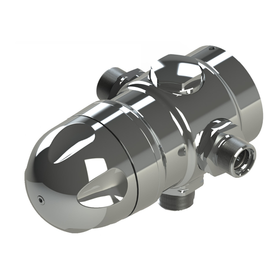
Model 320
Model No.
Serial No.
Ship Date
q Model 320
q Model 320D
:
:
Keep this manual with installation for
future reference.
Advertisement
Table of Contents

Related Manuals for Armstrong 3031S


Summary of Contents for Armstrong 3031S
- Page 1 Water Temperature Controls Groups of Fixtures - Thermostatic Model No. q Model 320 q Model 320D Serial No. Ship Date Armstrong International Keep this manual with installation for 221 Armstrong Blvd., Three Rivers, Michigan, 49093 - USA future reference. armstronginternational.com/brain...
-
Page 2: Table Of Contents
Contents Introduction .............. 3 Specifications ............5 General Advisory ............. 5 Safety ..............6 Pack Contents ............7 Schematic Piping ............. 8 Installation ............... 9 General ..............9 Installation Requirements ........9 Tools Required ............ 9 Installation Procedure ........10 Commissioning ............ -
Page 3: Introduction
75.7 83.3 87.1 90.8 Designs, materials, weights and performance ratings are Armstrong Hot Water Group, 221 Armstrong Blvd., Three Rivers, MI 49093 – USA approximate and subject to change without notice. Visit Phone: 269-279-3602, Fax: 269-279-3130 armstronginternational.com for up-to-date information. - Page 4 75.7 83.3 87.1 90.8 Designs, materials, weights and performance ratings are Armstrong Hot Water Group, 221 Armstrong Blvd., Three Rivers, MI 49093 – USA approximate and subject to change without notice. Visit Phone: 269-279-3602, Fax: 269-279-3130 armstronginternational.com for up-to-date information.
-
Page 5: Specifications
General Advisory This Model 320 Valve has been supplied for this application based upon information provided to Armstrong at the time the order was placed. This Model 320 Valve is configured for use in a “dead-leg” piping configuration. -
Page 6: Safety
• IPC (International Plumbing Code) Read this manual Improper installation or operation may cause a flood resulting in property damage, personal injury, or death. Armstrong strongly recommends that a qualified installer be used. Service must be performed by a qualified person. -
Page 7: Pack Contents
Pack Contents... -
Page 8: Schematic Piping
Schematic Piping Model 320 Water Heater System Layout Thermometer Isolation Valve Sink Stop Valve Shower Flow Direction Check Valve Pipeline... -
Page 9: Installation
Installation General Installation must be carried out in accordance with these instructions, and must be conducted by designated, qualified and competent personnel. The installation must comply with all relevant local and state water plumbing codes. All plumbing components are to be supplied by the installer. Failure to include these components will compromise the product, system performance and will void the warranty. -
Page 10: Installation Procedure
Step 1 Step 2 Ø 6 mm 2.5 mm 6.0 mm a. Use the Backplate to mark the four mounting holes at a. Unscrew the set screw. the desired height. b. Remove the Backplate. b. Drill the holes (6 mm) and fit the wall anchors. Screw the Backplate to the wall. - Page 11 Step 5 Model 320 must be installed in a standard HOT-LEFT/COLD-RIGHT inlet supply configuration. There are red (hot) and blue (cold) markings on each valve. The inlet supplies must always match the corresponding inlet ports on the valve. Step 6 Step 7 a.
-
Page 12: Commissioning
Commissioning Model 320 is designed for two types of configurations: 1. Locked Temperature (Temperature control is locked and cannot be adjusted) 2. Adjustable Temperature (Temperature can be adjusted through a desired range) The following steps show the procedure for both type of installations: Step 2 Step 1 3 mm... -
Page 13: Operation
Step 4 Exercising the Thermostat Thermostatic mixing valves with thermostats are inclined to lose their responsiveness if not used. Valves which have been in storage, installed but not commissioned, or simply not used for some time should be exercised before setting the maximum temperature or carrying out any tests. -
Page 14: Servicing & Maintenance
Servicing & Maintenance Warning! Isolate water supply to Model 320 before proceeding. Model 320 Thermostatic Mixing Valves and its components should be inspected annually, or more frequently where acknowledged site conditions such as high mineral content water dictate. Model 320 Thermostatic Mixing Valve is of a sealed single “cartridge construction”. The cartridge can be removed from the valve for inspection or replacement. - Page 15 Step 2 ‘H’ and ‘C’ marked on cartridge. Make sure that the ‘H’ is lined up with the hot inlet and that the ‘C’ is lined up with the cold inlet Disassembly Unscrew the knob using a 3mm Allen Key. Remove the Knob and Hub.
- Page 16 Cleaning/Renewal of Parts Internal parts (with the exception of the Thermostat Assembly) can be cleaned using a mild proprietary inhibited scale solvent e.g. domestic kettle descalent. After descaling, always rinse parts thoroughly in clean water before refitting. Note! The body interior must be cleaned carefully and not damaged in any way. Do not use any abrasive material.
-
Page 17: Spare Parts
Model 320 Spare Parts D90919 D90916 D94464 D58389 D33388 D90917 D33385 D33390 Part No: Description Note D33385 Hub Pack D33390 Knob Pack D58389 Cartridge Assembly D90916 Seal Pack D33388 Screw Pack D90917 Indicator Trim D90918 3/4” Check Valve Service Pack - 1 Pair D80012 3/4”... -
Page 18: Troubleshooting
Troubleshooting Fault Diagnosis Read the section “Important Safety Information” first. If any maintenance is required then it must be carried out by a competent tradesperson. Before replacing any parts make sure that the underlying cause of the malfunction has been resolved. Warning! There are no user serviceable components beneath the casing of the appliance. - Page 19 5. Mixed water a. Mixing Valve set too high and has not Refer to Commissioning - Rectify. temperature too high. been commissioned correctly. b . M i x i n g Va l v e h a s n o t b e e n Refer to Commissioning - Rectify.
-
Page 20: Limited Warranty And Remedy
Armstrong products, notice of any warranty or other claim relating to the products must be given in writing to Armstrong: (i) within 30 days of last day of the applicable warranty period, or (ii) within 30 days of the date of the manifestation of the condition or occurrence giving rise to the claim, whichever is earlier.