
Related Manuals for Armstrong CD72SR


Summary of Contents for Armstrong CD72SR
- Page 1 CD72SR Control Disc Steam Trap Installation and Operation Manual Please read and save these instructions IOM-31-V1.0-EN...
-
Page 2: Table Of Contents
Table of Contents General Safety Information ......Product Information ........Product Installation ........Maintenance Requirements ...... Trouble Shooting ......... Repair Parts ........... Designs, materials, weights and performance ratings are approximate and subject to change without notice. Visit armstronginternational.com for up-to-date information. North America •... -
Page 3: General Safety Information
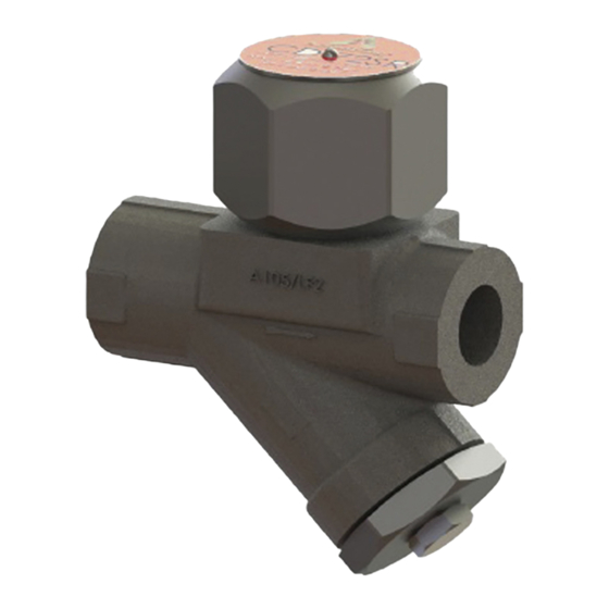
International Inc., or its local sales representative for additional information. Product Information Armstrong CD72SR is a disc styled trap designed to control the trap’s cycle rate. The reduced cycle rate provides Armstrong CD72SR trap with a longer service life than typical disc traps. This enhanced performance ensures minimum maintenance time and reduced steam costs. -
Page 4: Maintenance Requirements
Theoretically the seats may be lapped or machined, however, any alteration of the internal components of any disc trap can change its operating characteristics. Armstrong does not recommend re-lapping the seating area of the Series CD Controlled Disc Traps. - Page 5 3. Gently remove the seat, disc, three alignment pins and the inner gasket. 4. If the trap is to be rebuilt, inspect the top surfaces of the body (highlighted below) for steam cutting, nicks, gouges or any other visible signs of damage. Also inspect the exposed threads of the body for any damage.
- Page 6 REASSEMBLY CONTENTS OF REBUILD KIT CAP - 1 NO. DISC - 1 NO. SEAT - 1 NO. (with name-plate embedded) INNER GASKET - 1 NO. ALIGNMENT PINS - 3 NOS. 1. Firmly secure the trap body with a vise and exposed threads facing upwards. 2.
- Page 7 3. Apply anti-seize paste to the cap threads on the body. Anti-seize paste 4. Place the alignment pins (3 nos.) and the inner gasket in th body as shown below: 5. Place the seat on the top of the body as shown below. Ensure that the alignment pins line up with the holes in the bottom of the seat.
- Page 8 6. Gently clean the surface with a soft damp cloth as shown below. Inspect the surfaces fro any nicks, gouges or any other visible signs of damage. Clean and insect the surface. 7. Place the disc on top of the seat. The groove in the disc should be facing downwards. Ensure that the disc is centered on the seat.
-
Page 9: Troubleshooting
9. Slowly slide the cap over the seat and disc. Gently thread the cap down by hand until it stops and tighten it. Gently shake the trap and look for sound of disc moving inside the cap. Now proceed to the next step. If the disc cannot be heard moving inside the cap, it may be caught between the cap and the seat. -
Page 10: Repair Parts
To order for replacement of Control disc, Seat and Screen please specify the model details and the size of the trap. For further assistance contact Armstrong representative. The repair components and their respective part numbers are listed in the table below:... - Page 11 Armstrong products, notice of any warranty or other claim relating to the products must be given in writing to Armstrong: (i) within 30 days of last day of the applicable warranty period, or (ii) within 30 days of the date of the manifestation of the condition or occurrence giving rise to the claim, whichever is earlier.