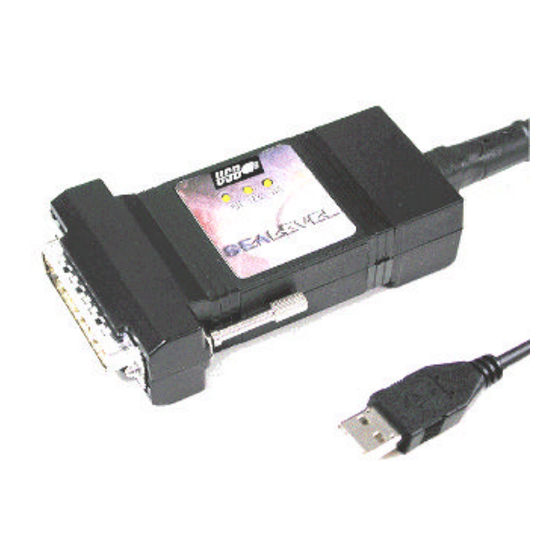
Summary of Contents for SeaLevel SeaLINK+ 485
- Page 1 SeaLINK+485 USER MANUAL Part # 2102 Sealevel Systems, Inc Phone: (864) 843-4343 155 Technology Place FAX: (864) 843-3067 P.O. Box 830 www.sealevel.com Liberty, SC 29657 USA...
-
Page 2: Table Of Contents
Contents ................ 1 NTRODUCTION ...................1 VERVIEW ’ ................1 NCLUDED ................2 NSTALLATION ............2 PERATING YSTEM NSTALLATION ...............2 YSTEM NSTALLATION ..............6 ONFIGURATION .............6 LECTRICAL NTERFACE ELECTION ................7 WITCH XAMPLES ............8 ECHNICAL ESCRIPTION ....................8 EATURES (DB25 M ) ........8 ONNECTOR SSIGNMENTS ............... - Page 3 Figure 1- RS-530/422 4 Wire 485 (Default) ............ 7 Figure 2 - RS-485, 2 Wire with Echo ............... 7 Figure 3 - RS-485, 2 Wire No Echo ..............7 Figure 4 - Asynchronous Communications Bit Diagram....... 14 © 2001c Sealevel Systems, Incorporated. All rights reserved.
-
Page 4: Introduction
Introduction Introduction Overview The Sealevel Systems SeaLINK+485 equips the PC with 1 USB to RS-530/422/485 Asynchronous serial port providing a versatile interface for common RS-530/422/485 needs. The advantage of this product over more traditional approaches is that it doesn’t require opening the computer case, nor does it require resources such as I/O ports or IRQ’s. -
Page 5: Installation
SeaLINK+485: requires no user hardware configuration since there are no jumpers present on the card. 1. Connect SeaLINK+485 to an Upstream Host or Hub. This indicates that the system has recognized the new device and will now proceed to locate a driver. Sealevel Systems SeaLINK+485 Page 2... - Page 6 Installation Since you have already installed the software by running “Setup”, simply click “Next” to proceed. The drivers that were installed during setup will automatically be used to configure the adapter for use. Sealevel Systems SeaLINK+485 Page 3...
- Page 7 Found”, indicating the actual port being created. If you view your systems Device Manager at this point, you should have a new “COM” port in the Port(COM & LPT) Device Class. It should look similar to the screen shot on the following page. Sealevel Systems SeaLINK+485 Page 4...
- Page 8 In this case, it is COM5: but this assignment will vary from system to system. At this point, the hardware is recognized. To verify operation use Sealevel Systems supplied WinSSD diagnostic utility. WinSSD can be found in the Start, Programs group. Sealevel Systems SeaLINK+485...
-
Page 9: Configuration
Adds or removes the 1K ohm pull-down resistor in the RS-422/RS-485 receiver circuit (Receive data only) Connects the TX+ to RX+ for RS-485 two wire operation Connects the TX- to RX- for RS-485 two wire operation Not Used Sealevel Systems SeaLINK+485 Page 6... -
Page 10: Switch Examples
1 2 3 4 5 6 7 8 Figure 2 - RS-485, 2 Wire with Echo R S - 4 8 5 1 2 3 4 5 6 7 8 Figure 3 - RS-485, 2 Wire No Echo Sealevel Systems SeaLINK+485 Page 7... -
Page 11: Technical Description
Input Transmit Positive Output Transmit Negative Output RTSB RTS+ Request To Send Positive Output RTSA RTS- Request To Send Negative Output DTRB DTR+ Data Terminal. Ready Positive Output DTRA DTR- Data Terminal Ready Negative Output Sealevel Systems SeaLINK+485 Page 8... -
Page 12: Specifications
Non-Condensing Non-Condensing Manufacturing • All Sealevel Systems Printed Circuit boards are built to UL 94V0 rating and are 100% electrically tested. These printed circuit boards are solder mask over bare copper or solder mask over tin nickel. Power Consumption Supply line... -
Page 13: Appendixa - Troubleshooting
3. When the SeaLINK+485 is configured properly, the USB Enabled LED (EN) will be lit. This should allow you to use Sealevel’s WinSSD utility and the supplied loopback plug to check communications. The supplied loopback plug connects TD to RD. If you decide to test the Modem Control Signals, a full pin loopback plug will be required. -
Page 14: Appendixb - How T O Get Assistance
If possible, please have the adapter connected in a computer ready to run diagnostics. 3. Sealevel Systems provides an FAQ section on its web site. Please refer to this for many commonly asked questions. This section can be found at http://www.sealevel.com/faq.htm... -
Page 15: Appendixc - Electrical Interface
The RS-530 specification defines two types of interface circuits, Data Terminal Equipment (DTE) and Data Circuit- Terminating Equipment (DCE). The Sealevel Systems adapter is a DTE interface. RS-422 The RS-422 specification defines the electrical characteristics of balanced voltage digital interface circuits. - Page 16 (Tx+ to Rx+ and Tx- to Rx-). Four wire mode allows full duplex data transfers. RS-485 does not define a connector pin-out or a set of modem control signals. RS-485 does not define a physical connector. Sealevel Systems SeaLINK+485 Page 13...
-
Page 17: Appendixd - Asynchronous Communications
The communication parameters are baud rate, parity, number of data bits per character, and stop bits (i.e. 9600,N,8,1). Sealevel Systems SeaLINK+485 Page 14... -
Page 18: Appendixe - Compliance Notices
Always use cabling provided with this product if possible. If no cable is provided or if an alternate cable is required, use high quality shielded cabling to maintain compliance with EMC directives. Sealevel Systems SeaLINK+485 Page 15... -
Page 19: Warranty
Sealevel Systems, Inc. provides a lifetime warranty for this product. Should this product fail to be in good working order at any time during this period, Sealevel Systems will, at it's option, replace or repair it at no additional charge except as set forth in the following terms.


Need help?
Do you have a question about the SeaLINK+ 485 and is the answer not in the manual?
Questions and answers