Table of Contents
Advertisement
Quick Links
Advertisement
Table of Contents

Subscribe to Our Youtube Channel
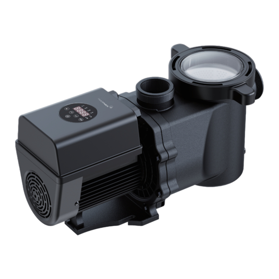
Summary of Contents for Madimack invermac inverFLOW INVFLO300
- Page 1 INSTALLATION MANUAL Powered by...
-
Page 2: Table Of Contents
Adherence to the directions for use in this manual is PLEASE READ THE MANUAL CAREFULLY BEFORE extremely important for health and safety. Failure to INSTALLATION & OPERATION AND RETAIN IT FOR strictly adhere to the requirements in this manual FUTURE REFERENCE. may result in personal injury, property damage and affect your ability to make a claim under the manufacturer’s warranty provided with your product. -
Page 3: Technical Specifications
2. TECHNICAL SPECIFICATIONS INPUT POWER Voltage Max Flow Head Max Circulation Advised Model (V/Hz) (L /min) Power Power Flow at 8m Flow at 10m l Volume L/min L/min 220~240 INVFLO300 30~70 0.75 1.00 16.0 50/60 220~240 INVFLO400 50~100 1.00 1.50 18.0 50/60 3. -
Page 4: Pump Location
continue INSTALLATION 4.2 Pump Location 4.3 Piping The pump should be installed in an area with at least 150mm Suction and return connections on the pool pumps are 50mm distance around the unit away from any obstacles and away pressure pipe dimensions. from any corrosive products. -
Page 5: Setting And Operation
5. SETTING AND OPERATION 5.1 Display on control panel: Unlock To change the value of the setting. DOWN Timer setting / power reading On/ Off Running capacity / power display Running capacity / power indicator Timer indicator 1/2/3/4 5.2 Startup When the power is switched on, the screen will fully light up for 3 seconds, the device code will be displayed, and then it will enter the normal working state. -
Page 6: Running Capacity Setting
continue SETTING AND OPERATION 5.4 Running Capacity Setting Note: a. When the running capacity is adjusted, the system will save the Hold for more than 3 seconds to unlock the latest parameter automatically. screen. b.When setting 100% speed, the pump will increase the speed automatically if the pipeline resistance is high, but will not exceed Press to start. -
Page 7: External Control
6. EXTERNAL CONTROL External control can be enabled via following contacts. Connector Digital input AC power input AC POWER OUTPUT Name Color Description etting Range Default Setting PIN 1 Digital Input 4 30~100%, by 5% increments ACL ACN PE PIN 2 Black Digital Input 3 30~100%, by 5% increments... -
Page 8: Protection And Failure
7. PROTECTION AND FAILURE 7.1 High Temperature Warning and Speed Reduction During normal operation (except backwash/self-priming), when the pump control system reaches the high temperature warning trigger threshold (81°C), it enters the high temperature warning state; when the temperature drops from the hightemperature warning release threshold (78°C), the high temperature warning state is released. -
Page 9: Maintenance
8. MAINTENANCE Empty the strainer basket frequently. The basket should be inspected through the transparent lid and emptied when there is an evident stack of rubbish inside. The following instructions should be followed: 1). Disconnected the power supply. 2). Unscrew the strainer basket lid anti-clockwise and remove. 3). -
Page 10: Diagram
10. DIAGRAM 10.1 Exploded view Explosive Explosive Part Name Quantity Part Name Quantity Diagram Code Diagram Code T union Parallel key O-ring (62×4.5mm) Inverter controller Fan cover Union nut Strainer basket Cross recess head screw O-ring (for Transparent Lid) (128×5.3mm) Motor Transparent Lid Base... -
Page 11: Warranty & Exclusions
LIMITED WARRANTY Madimack warrants that its products are free from defects in materials and manufacture for a period of 3 years from the date of purchase, unless otherwise specified. - Page 12 AG045-DE-05...


Need help?
Do you have a question about the invermac inverFLOW INVFLO300 and is the answer not in the manual?
Questions and answers