Table of Contents
Advertisement
Quick Links
Advertisement
Table of Contents

Related Manuals for Madimack INVPLUS1100


Summary of Contents for Madimack INVPLUS1100
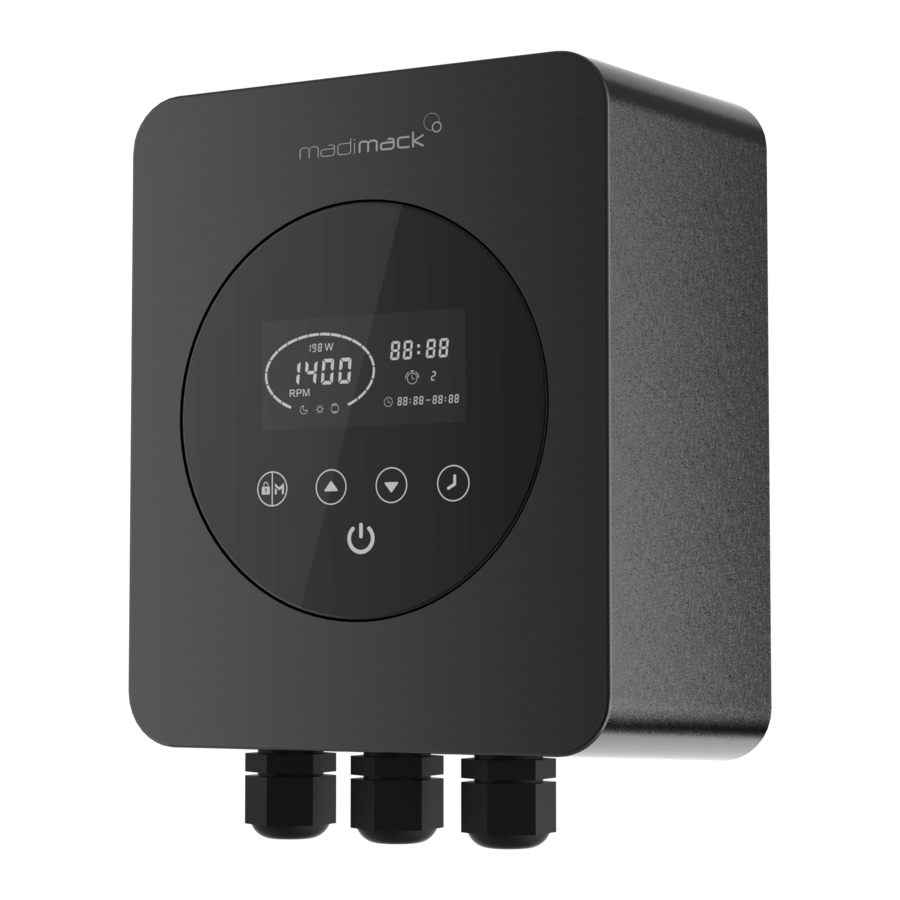
- Page 1 MADIMACK VARIABLE SPEED PUMP INVERTER INSTALLATION & USER GUIDE INVPLUS1100, INVPLUS2200 Thank you for purchasing our variable speed pump controller. Please read the manual carefully before installation & operation and keep it for future reference after installation.
-
Page 3: Table Of Contents
CONTENTS IMPORTANT SAFETY INSTRUCTIONS ..............1 TECHNICAL DATA ....................2 BEFORE INSTALLATION ..................2 CONNECTING TO POOL PUMP ................3 SETTINGS & OPERATION ..................4 PROTECTION & ERROR CODES ................7 COMMISSIONING AND CHECKS ................8 EXCLUSIONS ......................8 WARRANTY ......................8 10. -
Page 4: Important Safety Instructions
1. IMPORTANT SAFETY INSTRUCTIONS To make the best use of this energy saving device and to avoid potential risk of fire, electrical shock, serious injury to people or damage to property, please read this user guide carefully before installation and keep it for future reference. This device can only be used with pumps with permanent split capacitor motor. -
Page 5: Technical Data
2. TECHNICAL DATA Model INVPLUS1100 INVPLUS2200 Dimensions Input power 1 phase AC 1 phase AC Input voltage 220~240V 220~240V Input frequency 50Hz 50Hz Output power Max 1.1kW Max 2.2 kW Output Voltage 1ph, 0~240V 1ph, 0~240V Pump type Single phase Single phase Max. -
Page 6: Connecting To Pool Pump
4. CONNECTING TO POOL PUMP Please follow these steps and the wiring diagram for the correct connection. The warranty may be compromised if the device is not installed in accordance with instructions described in this manual. Only ONE pump can be connected to the inverter. Please do not connect any other appliance to the output. -
Page 7: Settings & Operation
5. SETTINGS & OPERATION 5.1 Control panel Current time Power Consumption Speed in rpm Night/Day/Backwash Timer on/Timer off (Low/Med/High speed) Timer Unlock/Change Mode Increase/Decrease On/Off 5.2 Mode selection The variable speed controller has 3 modes (speed ranges). You can either run your pump at a constant speed choosing from “M”... - Page 8 5.3 Timer setting Note: If the unit is not operating and the symbol is flashing this means that it is waiting for the next on timer to start. To run the pump at a different times or speeds to take advantage of lower electricity tariffs during the night or for higher speed cleaner operation, you can set up to 4 timers.
- Page 9 5.4 External control External control can be enabled via the following contacts. However, even if it’s working via an external controller, pressing can stop the device. Please do not apply voltage to these inputs. DIGITAL INPUT RELAY OUTPUT Fig 5 ANALOG INPUT RS485 E.g.: To enable external speed control via digital input, connect one of the digits from Di2/3/4...
-
Page 10: Protection & Error Codes
If code continues to be displayed please contact the Madimack support line on 1300 899 737 or email support@madimack.com.au... -
Page 11: Commissioning And Checks
User Guide without notice in case of technical upgrade. Madimack are not responsible for the failure of any pump connected to the device. The variable speed controller should not be installed in exposed locations or corrosive environments. - Page 12 MA001...
Need help?
Do you have a question about the INVPLUS1100 and is the answer not in the manual?
Questions and answers