Table of Contents
Advertisement
Advertisement
Table of Contents

Related Manuals for Tool Shop 240-2003


Summary of Contents for Tool Shop 240-2003
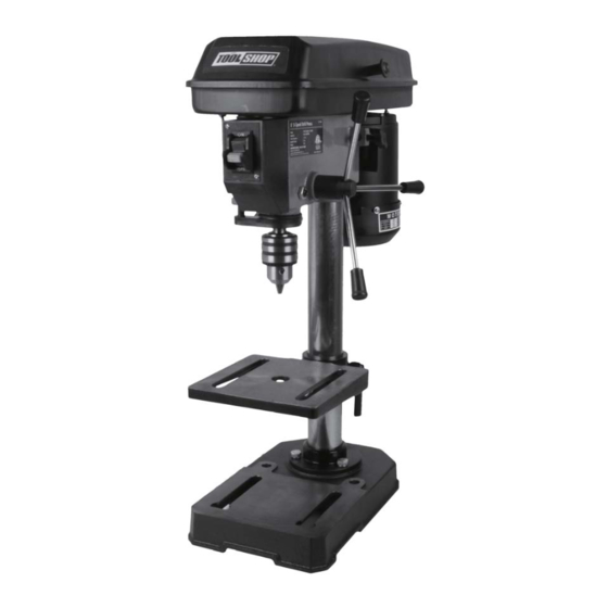
- Page 1 240-2003 DRILL PRESS Operator’s Manual SAVE THIS MANUAL You will need this manual for safety instructions, operating procedures and warranty. Put it and the original sales receipt in a safe dry place for future reference. For questions about this product, please call 1-866-915-8626.
-
Page 2: Important Safety Instruction
IMPORTANT SAFETY INSTRUCTION When using electric tools, machines or equipment, basic safety WARNING: precautions should always be followed to reduce the risk of fire, electric shock, and personal injury. READ INSTRUCTIONS BEFORE USING THIS TOOL 1. KEEP WORK AREA CLEAN. Cluttered areas invite injuries. 2. - Page 3 IMPORTANT SAFETY INSTRUCTION 14. DRESS PROPERLY. Don’t wear loose clothing or jewelry; they can be caught in moving parts. Protective, non-electrically conductive gloves and non-skid footwear are recommended when working. Wear protective hair covering to contain long hair and keep it from harm. 15.
- Page 4 SAFETY PRECAUTIONS FOR DRILL PRESS 6. Never perform layout, assembly, or set-up work on the table while the drill is in use. 7. Make sure drill bit is securely locked in the chuck. 8. Make sure chuck key is removed from the chuck before turning power on. 9.
-
Page 5: Function Description
SPECIFICATIONS Voltage: 120V ~ 60Hz, Current Rating: 3.0 Amps Spindle Speed: 740 , 1100 , 1530 , 2100 , 3140 RPM (No Load) Chuck Capacity: 1/2" Spindle travel: 2" Spindle Attachment: JT33 Table Height Adjustment: 8-1/2" Swing: 8" Contents:(1) Chuck Key (2) 1/8"... -
Page 6: Assembly And Adjustments
ASSEMBLY AND ADJUSTMENTS WARNING: To reduce the risk of injury, never connect plug to power source outlet until all assembly steps are completed. Base to column (See Fig. 1) 1. Place Colum n (1) on the Base (3) and align holes in the Column with holes in the Base. - Page 7 ASSEMBLY AND ADJUSTMENTS Install the chuck (see Fig. 4 ). 1. Inspect and clean the taper hole in the chuck and the spindle. Remove all grease, coatings, and particles from the chuck and spindle surfaces with a clean cloth. 2. Open the chuck jaws by turning the chuck barrel clockwise by hand.
- Page 8 ASSEMBLY AND ADJUSTMENTS WARNING: Disconnect the drill press from the power source before making any speed adjustments. Adjust speeds and tension the belt 1. Open the drill press pulley cover. 2. Loosen the belt tension knob (2) (see Fig 7). 3.
- Page 9 ASSEMBLY AND ADJUSTMENTS Coil spring adjustment (See Fig. 11) WARNING: Disconnect the drill press from the power source before adjustment . If the quill (8) returns too quickly or too slowly when the handles are released, adjust the spring. Note: This adjustment is set at the factory and should not need changing.
-
Page 10: Operation
ASSEMBLY AND ADJUSTMENTS 11. If the quill (8) returns gently to top position (correct operation): ‡ Tighten the inner nut (4). Do not overtighten. ‡ Replace the jam nut (3). Tighten against the inner nut. ‡ Remove the screwdriver. ‡ Rotate the handles and check the quill (8) for unrestricted movement. -
Page 11: Maintaining Your Drill Press
OPERATION 4. Select your drilling depth and secure the depth stop lock knob in position. 5. Adjust the table to your desired position. 6. Slowly rotate the wheel handles to bring the drill bit down towards the table and into your workpiece. After drilling a hole, release the wheel handles slowly to return the chuck to its original position. - Page 12 PARTS LIST AND SCHEMATIC DRAWING '(6&5,37,2 '(6&5,37, 1 BASE RULER HOLDER MAIN SPINDLE COLUMN FLANGE FLAT WASHER CHUCK SPRING WASHER HEXAGON BAR WRENCH OUTSIDE HEX. BOLT HEXAGON BAR WRENCH OUTSIDE HEX. BOLT HEX. SOC SET SCREW SPRING WASHER MOTOR PULLEY WORKING TABLE CIRCLIP FOR HOLE TABLE SUPPORT...
- Page 13 PARTS LIST AND SCHEMATIC DRAWING WARNING: Repairs should be made by an authorized repair center. Do not open or disassemble this power tool.Contact at 1-866-915-8626 for questions regarding this power tool.
- Page 14 TOOL SHOP® 8 IN. DRILL PRESS 1-YEAR LIMITED WARRANTY: This brand power tool carries a 1-Year Limited Warranty to the TOOL SHOP® original purchaser. If the tool fails within one (1) year from the date of purchase, simply bring this tool with your original sales receipt back to your nearest retail store.
Need help?
Do you have a question about the 240-2003 and is the answer not in the manual?
Questions and answers