Table of Contents
Advertisement
Advertisement
Table of Contents

Related Manuals for Man D 0836 LE 401


Summary of Contents for Man D 0836 LE 401
- Page 3 Operating Instructions − MAN Marine Diesel Engines...
-
Page 5: Preface
You can find the approved products in the internet under: −http://www.man-mn.com/ " Products & Solutions " E-Business− It is imperative and in your own interest to entrust your MAN Local Service Centre with the removal of any disturbances and with the performance of checking, setting, and repair work. -
Page 6: Instructions
Flat seals / gaskets can be fitted properly only if the following points are ob- served: D Use only genuine MAN seals / gaskets D The sealing faces must be undamaged and clean D Do not use any sealing agent or adhesive − as an aid to fitting the seals a little grease... -
Page 7: Table Of Contents
..........Engine views D 0836 LE 401 . -
Page 8: Declaracion
In accordance with Article 4, paragraph 2, in conjunction with Appendix II, section B, of Directive 89/392/EEC, version 93/44/EEC MAN Nutzfahrzeuge Aktiengesellschaft, hereby declares that the engine described below is destined for installation in a machine as defined in the EC directive on machines. - Page 9 Declaracion...
-
Page 10: Nameplates
The engine type plates are on the crank- case..............delivered on ..............installed on ..............Engine serial number ..............Order number ..............MAN Nutzfahrzeuge Aktiengesellschaft Motor-Nr. / Engine No. NI/II MAN Nutzfahrzeuge Aktiengesellsc MAN Nutzfahrzeuge Aktiengesellschaft Werk Nürnberg Germany Bauj. Year Model Motor−Nr. Serial No Werk−Nr. -
Page 11: Safety Regulations
Safety regulations General notes Day-to-day use of power engines and the service products (fuels, lubricants, cool- ants) necessary for running them presents no problems if the persons occupied with their operation, maintenance and care are given suitable training and think as they work. - Page 12 D Exhaust gases are toxic. Comply with the instructions for the installation of MAN Diesel engines which are to be operated in enclosed spaces. Ensure that there is adequate ventilation and air extraction.
- Page 13 Safety regulations D Change the oil when the engines is warm from operation. Caution: There is a risk of burns and scalding. Do not touch oil drain plugs or oil filters with bare hands. Ë Ë D Take into account the amount of oil in the sump. Use a vessel of suffi- cient size to ensure that the oil will not overflow.
- Page 14 If faults occur, find the cause immediately and have it eliminated in order to prevent more serious damage. Use only genuine MAN spare parts. MAN will accept no responsibility for damage result- ing from the installation of other parts which are supposedly “just as good”.
- Page 15 Safety regulations 3. Regulations designed to prevent pollution Engine oil and filter elements / cartridges, fuel / fuel filter D Take old oil only to an old oil collection point. D Take strict precautions to ensure that no oil or Diesel fuel gets into the drains or the ground.
- Page 16 Safety regulations 4. Notes on safety in handling used engine oil ∗ Prolonged or repeated contact between the skin and any kind of engine oil decreases the skin. Drying, irritation or inflammation of the skin may therefore occur. Used engine oil also contains dangerous substances which have caused skin cancer in animal experi- ments.
- Page 17 Notes ..........................................................................................................................................................................................................................................................................................................................................................................................................................................................................................................................................................................................................................................................................................................................................................................................
-
Page 18: Commissioning And Operation
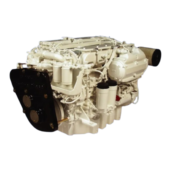
Commissioning and operation Engine views D 0836 LE 401... - Page 19 Commissioning and operation 1 Coolant filler neck 2 Intercooler 3 Air filter 4 Starter motor 5 Oil filler neck 6 Oil dipstick 7 Oil filter 8 Injection pump 9 Prestrainer 10 Fuel filter 11 Water pump (engine coolant circuit) 12 Crankcase breather 13 Hand primer 14 Generator 15 Raw water pump...
-
Page 20: First Commissioning
When putting a new or overhauled engine into operation for the first time pay attention to the “Installation instructions for MAN marine diesel engines” without fail. It is recommended that new or overhauled engines should not be operated at a load higher than about 75% maximum load during the first few hours of operation. - Page 21 Commissioning and operation Raw water pump Do not let raw water pump run dry! Make sure that all valves / cocks in the raw water circuit are open. If there is a risk of frost, drain the raw water pump. Filling with engine oil Caution: Do not add so much engine oil...
-
Page 22: Commissioning
Commissioning and operation Commissioning Before daily starting the engine, check fuel level, coolant level and engine oil level and replenish, if necessary. Note: Use only approved fuels, lubricants etc. (see brochure “Fuels, lubricants etc.”). Otherwise the manufacturer’s warranty will become null and void. Checking oil level Check engine oil level only approx. -
Page 23: Starting
Commissioning and operation Starting Danger: Before starting make sure that no-one is in the engine’s danger area. Caution: When starting do not use any additional starting aids (e.g. injection with starting pilot). Ensure that the gearbox is in neutral. Insert starter key and turn it to position“I”. Readiness for operation is indicated by the lighting up of a check lamp which may have been installed by the shipyard. -
Page 24: Operation Monitoring System
Commissioning and operation Operation monitoring system The D 0836 LE 401 is fitted as standard with an MMDS-D08 monitoring and diagnostic system and with a display unit for alarms, the MMDS-D08-L, see page 28. The shipyard should also have installed round instruments for engine speed, engine oil pressure and gearbox oil pressure, a voltmeter and as an option (exhaust gas tempera- ture gauge, engine oil temperature gauge). -
Page 25: Tachometer Can-Master
Commissioning and operation Tachometer CAN-Master The VDO Ocean Link Tachometer (CAN-Bus Tachometer) The VDO Ocean Link tachometer is a multifunctional instrument for indicating engine data, and is intendet for use in na- vigation of sports ships. The tachometer shows the actual engine speed in opera- tin, on the analogue scale. - Page 26 Commissioning and operation Setting possibilities Further settings can be made by pressing the button: D Selection of illumination intensity in 8 steps D Selection of display unit in metric or english units D Selection of transmitters for the analogue inputs Selection of illumination intensity If you keep the push-button key pressed for 4 seconds, the roll bar for the illumination setting appears.
- Page 27 Commissioning and operation Setting the illumination (external illumination) Select here whether illumination of the tachometer and the connected bus instruments are to be connected internally or externally. EXTERNAL: The illumination is switched on and off through an input of the 14-pole plug. Dimming of the illumination is thus not possible.
- Page 28 Commissioning and operation Monitoring / alarm system MMDS D08-L MAN MARINE DIESEL Port Starboard Engine in operation Engine in operation Generator/speed sensor Generator/speed sensor Engine oil pressure Engine oil pressure Engine oil temperature Engine oil temperature Engine coolant temp. Engine coolant temp.
- Page 29 Commissioning and operation System fault: There are 2 different failure states, which are indicated by the failure LED flashing or being continuously lit: − A flashing system fault LED indicates a communication fault, i.e. at least one of the data buses is interrupted or disturbed. In this case, the plug connections on the MMDS D08-L and the MMDS-SD serial distribution box must be checked for correct seating.
- Page 30 Monitoring / alarm system D MMDS-L display unit (option) This display unit shows the alarms from one engine. The engine monitoring system alarms the MAN MARINE DIESEL helmsman if important engine operating values are outside the permissible toler- Boost pressure Engine in operation ances.
- Page 31 Commissioning and operation Operation of the display device MMDS-L The display device has the following operating keys: Switches off the alarm horn and the integrated buzzer Switches off the flashing signal of the relevant warning lamp, i.e. the flashing light switches to continuous light.
- Page 32 Monitoring / alarm system D MMDS-LC display unit (option) The device serves to visualise analog en- MAN MARINE DIESEL gine data, as well as visual and acoustic notification of engine alarms. All engine data is entered at the factory in the lan-...
- Page 33 Commissioning and operation Page 1 Actual value (example) Engine speed 2100 Engine oil pressure Coolant temperature, engine °C °C Charge-air temperature Gearbox oil pressure Page 2 Actual value (example) Engine speed 2100 Coolant pressure compensator mbar reservoir. Coolant pressure water pump Engine oil temperature °C Battery voltage...
- Page 34 Commissioning and operation The following codes are distinguished: Warnings: without code Warnings (preliminary alarms): WA Main alarms: Sensor error alarms: Example: Message text Code Time Coolant temperature: 14:14 Charge-air temperature 13:57 Coolant level 11:00 Engine oil pressure 08:37 Bilge pump ON Programmed ship-specific warning If there are more than 5 alarms (e.g.
- Page 35 Commissioning and operation System failure The front plate of the device has a red LED with the description System Failure. This is activated in the following two cases: A Failure of the serial data from the Safety, Alarm and Diagnosis system MMDS in the engine terminal box.
- Page 36 Commissioning and operation Standard function: The reset key can be used to reset a slow down or RESET: stop alarm: A reduction alarm can only be reset after reduction of R E S ET the speed below 800 rpm. If the corresponding criteria have been met, horn and optics / test button pressed / activated and the cause of the alarm eliminated, the reduction or stop alarm in the central processing unit is reset.
- Page 37 Commissioning and operation Menu functions By holding the “ALARMS” key (for at least 5 seconds), you enter the configuration menu. The keys are now given the significance described at “Menüfunktion”. The new allocation is shown in the bottom line in continuous black: Escape functionCancel Move functionMove selection Enter functionAccept setting...
- Page 38 Commissioning and operation Display in BAR Display in PSI > (BAR) < (PSI) After selection and acceptance, all the settings for language and unit have been con- cluded and highlighted accordingly in black. The selection cursor jumps to the second last line to the item“exit”: >exit<...
- Page 39 Commissioning and operation ALARMS If nothing is to be changed, you can cancel using the Menu key . Otherwise, the M en T E S T R E S ET setting is made using the + − keys and the PRG key in the order P rg Hour, Minute, Second, Day, Month and Year.
- Page 40 Marex SB or Mini Marex, both from Bosch-Rexroth. 1. Marex-SB This control system has plug connections specially made for MAN. It is a low-cost variant without trolling function and has control electronics for two engines in the engine room. Both the engine speed and the gearbox position (forward, neutral, reverse) are preset via the accelerator position.
- Page 41 Commissioning and operation Push−button key Command Lamps Push-button key COMMAND D Change of bridge ALARM D Quit alarm buzzer SYNCHRO D Activate special functions Synchronisation lamp Alarm Lamps Command lamps D Display showing whether bridge is active Alarm lamps D Display showing whether a fault is present Synchronisation lamp D Display showing whether synchronisa- tion is active...
- Page 42 Commissioning and operation Status : All lamps constantly on COMMAND Lamp test All lamps ALARM SYNCHRO Continous tone Push button key Accelerator in neutral Accelerator not in neutral Command lamp flashes fast Command lamp flashes slowly Status : COMMAND COMMAND of requesting ALARM ALARM...
- Page 43 Commissioning and operation Change of bridge A change of bridge can be carried out in two different modes: − Range comparison − Position comparison Range comparison mode Status : Passive COMMAND bridge ALARM SYNCHRO Press buttonactuate Accelerator position incorrect Accelerator position correct Status : Command lamp flashes slowly of requesting...
- Page 44 Commissioning and operation Warming Up With the special “Warming up” function a speed can be set without the gearbox being shifted. This function is necessary for letting the engines warm up. To switch on the “Warming up” function press the button at the active bridge and at the same time move the accelerator to forward or reverse.
- Page 45 Commissioning and operation 2. Drive lever control system Mini Marex At the request of the shipyard or customer, it is possible to purchase from MAN an elec- tronic drive lever control system made by Mannesmann Rexroth, type Mini Marex. This control system has plug connections specially configured for MAN.
- Page 46 Commissioning and operation “Maximum engine speed” position  Position  shows the “maximum engine speed” for the “Forwards and Backwards Range” Between positions Á and  the engine speed can be set variably. The gearbox clutch is engaged to “Forwards” or “Reverse”; Operating panel −...
- Page 47 Commissioning and operation 3. Set the control lever of the command master in position “Á gearbox forwards / re- verse”. The “Warming Up” function is indicated acoustically by a short “double beep” tone and visually by a brief, rhythmic extinguishing of the command master lighting. 4.
- Page 48 Commissioning and operation Engine speed synchronisation (only possible with twin-engine systems) If the special function “Engine speed synchronisation” has been enabled in the setting units, twin-engine systems provide the possibility to synchronise the engine speeds of both drive engines. For both drive engines to run synchronously, an engine speed feed- back signal from a speed sensor is required for each engine.
- Page 49 Commissioning and operation Neutral (lock) Gearbox: speed Gearbox: speed Clunch: 100% slip Clunch: 100% slip (lock) (lock) Infinitely variable Infinitely variable slip adjustment and slip adjustment and speed increase speed increase Reverse area Forwards area Operating field Clunch: 0% slip Clunch: 0% slip (grip) (grip)
- Page 50 Commissioning and operation Display Command L2 and L3 COMMAND Continuous light of the “Command” display indicates which command master is currently in command. The “Command” displays of the other control stands are disabled. If the command is requested on this master, the “Command” display flashes. If the command master is in the “Warming Up”...
- Page 51 DIP switch I-2 in the setting unit. Command change with lever comparison or free command change. Please ask your MAN agent. Command change with lever comparison The control system compares the lever positions of the command masters involved in the control stand change.
- Page 52 Commissioning and operation 2. step: Command request on the selected control stand. Execution: − Press “Command” key once to take over the command on this control stand. Consequence: − The acoustic signal transmitter is silent. − The “Command” display shows continuous light. The command takeover is complete and the command is now at this control stand.
- Page 53 Commissioning and operation Main fuses for + / − on the engine One main fuse with 20 A is fitted at the engine; these blow in the event of overcurrent or short circuit. If the fuse as blown, the engine can no longer be started. The fuse can be reset by the operator using the keys fitted.
- Page 54 Commissioning and operation Main fuses on terminal box Three more main fuses are fitted in the terminal box. These fuses blow in the event of overcur- rent or short circuit. They separately protect D the electronic fuel injection EDC, F5=16 A D the diagnosis system, F6=10 A D and the external electrical connections, F7=10 A...
- Page 55 Commissioning and operation Terminal box in the engine room / interface with light-emitting diodes + keys The terminal box with light-emitting diodes functions at the same time as an engine room monitoring panel. If an alarm is issued, the corresponding light-emitting diode lights up. The following re- lays are activated on the diagnosis unit: D Engine slow down (main alarm) = reduction of engine speed D Horn = acoustic alarm...
-
Page 56: Shutting Down
Commissioning and operation The following light-emitting diodes function continuously: D Power on: Diagnosis unit is receiving voltage D Ignition: Ignition is on D Serial data activity: Data interchange at the bridge. If this fails, no more data is displayed on the bridge, neither on the display (Display MMDS-D08/L /LC). -
Page 57: Maintenance And Care
Maintenance and care Lubrication system Ensure outmost cleanliness when handling fuels, lubricants and coolants. Caution: Use only approved fuels, lubricants etc. (see brochure “Fuels, lubricants etc.”). Otherwise the manufacturer’s warranty will become null and void. Refilling with oil Danger: The oil is hot-risk of scalding. Do not touch the oil drain plug with bare fingers. - Page 58 Maintenance and care Refilling with oil Caution: Do not add so much engine oil that the oil level rises above the max. marking on the dipstick. Overfilling will result in damage to the engine. Refill with fresh engine oil at the oil filler neck (arrow).
- Page 59 Maintenance and care Changing oil filter Caution: Used oil and oil filters are classed as dangerous waste and must de disposed of accordingly. Note in- structions for preventing environ- mental damage. Danger: Oil filter can and oil filter are filled with hot oil. Risk of burns and scalds! When the engine is at operating tempera- ture open the cover of the oil filter housing...
-
Page 60: Fuel System
Maintenance and care Fuel system Caution: Use only approved fuels, lubricants etc. (see brochure “Fuels, lubricants etc.”). Otherwise the manufacturer’s warranty will become null and void. Fuel If Diesel fuel which contains moisture is used the injection system and the cylinder liners / pistons will be damaged. - Page 61 Maintenance and care Parallel fuel filter Draining moisture: Unsrew drain plugs at every oil change until moisture has been discharged and clean fuel flows out Changing fuel filter Only when the engine is swiched off. D Remove filter cartridge using tape wrench.
- Page 62 Maintenance and care Changing fuel filter D Remove filter cartridge using tape wrench. D Wet seal on new filter with fuel D Screw on filter by hand D After this, bleed the fuel system D Check filter for leaks Caution: Used fuel filters are classed as dangerous waste and must be dis- posed of accordingly.
- Page 63 Maintenance and care If air gets into the high-pressure part of the injection pump (model VP 44) the sys- tem must be bled again. If the engine does not start after the tank has been run empty or after repairs to the fuel system the high-pressure system must be bled.
-
Page 64: Cooling System
Maintenance and care Cooling system Caution: Use only approved fuels, lubricants etc. (see brochure “Fuels, lubricants etc.”). Otherwise the manufacturer’s warranty will become null and void. Danger: Draining hot coolant involves a risk of scalding. Draining the cooling system Caution: Drain coolant into a suitable con- tainer and dispose of it in accord- ance with regulations. - Page 65 See Publication “Fuels, Lubricants and Coolants for MAN Diesel Engines”. Coolant must be added at the filler neck only (large cap). Do not put cold coolant into an engine which is warm from operation.
- Page 66 Maintenance and care Danger: There is a risk of burns and scalding. D Top up with coolant (approx. 5 litres) and refit cap À Before the engine is next put into oper- ation (with the engine cold) check the coolant level and top up if necessary. Note: The turbochargers must not be bled while the cooling system is being topped up.
-
Page 67: V-Belts
Maintenance and care V-belts Checking condition D Check V-belts for cracks, oil, overheat- ing and wear D Change demaged V-belts Checking tension Use V-belt tension tester to check V-belt tension. D Lower indicator arm À into the scale D Apply tester to belt at a point midway between two pulleys so that edge of contact surface Á... -
Page 68: Alternator
D Do not operate the alternator without battery connection! Temporary decommissioning of engines Temporary anti-corrosion protection according to MAN works norm M 3069 is required for engines which are to be put out of service for fairly long periods. The works norm can be obtained from our After-Sales Service department Nuremberg... - Page 69 Notes ..........................................................................................................................................................................................................................................................................................................................................................................................................................................................................................................................................................................................................................................................................................................................................................................................
-
Page 70: Technical Data
Technical data Model D 0836 LE 401 / 402 Design in-line vertical Cycle 4-stroke Diesel with turbocharging / inter- cooling and (wastegate) Combustion system Direct injection Turbocharging Turbocharger with intercooling and waste- gate Number of cylinders Bore 108 mm Stroke... - Page 71 Technical data Engine lubrication Force feed Oil capacity in oil sump (litres) min. max. 24 l 28 l Oil change quantity (with filter) 30 l Oil filter Full-flow filter with two paper filter ele- ments Engine cooling system Liquid cooling Coolant temperature 80 - 90°C, temporarily 95°C allowed Coolant filling quantity...
-
Page 72: Troubleshooting Table
Troubleshooting table Fault Engine does not start, or starts only with difficulty Engine starts but does not reach full speed or stalls Engine idles out of true when warm, misfiring Engine speed fluctuates during operation Power output unsatisfactory Coolant temperature too high, coolant being lost Lube oil pressure too low Lube oil pressure too high Black smoke accompanied by loss of power... - Page 73 Troubleshooting table Fault Engine does not start, or starts only with difficulty Engine starts but does not reach full speed or stalls Engine idles out of true when warm, misfiring Engine speed fluctuates during operation Power output unsatisfactory Coolant temperature too high, coolant being lost Lube oil pressure too low Lube oil pressure too high Black smoke accompanied by loss of power...
-
Page 74: Index
Index Alternator ....... . Operation monitoring Charge control lamp on the terminal box .
Need help?
Do you have a question about the D 0836 LE 401 and is the answer not in the manual?
Questions and answers