Diamond OPTIMA 700 Installation, Use And Maintenance Instructions
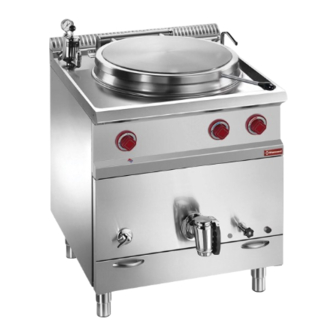
Gas-fed pan
Hide thumbs
Also See for OPTIMA 700:
- User manual ,
- Manua (89 pages) ,
- Installation, use and maintenance instructions (67 pages)
Table of Contents
Advertisement
Available languages
Available languages
Quick Links
Advertisement
Chapters
Table of Contents

Subscribe to Our Youtube Channel
Related Manuals for Diamond OPTIMA 700


Summary of Contents for Diamond OPTIMA 700
- Page 1 11/2010 Mod: G77/M50I7-N Production code: B-G50I77...
- Page 2 INSTALLATIONS-, BETRIEBS-UND WARTUNGSANLEITUNGEN INSTRUCCIONES PARA LA INSTALACIÓN, EL USO Y EL MANTENIMIENTO PENTOLA A GAS SERIE OPTIMA OPTIMA 700 SECONDO NORMA: EN 437 e EN 203 parte 1 e 2 Categoria II per Gas Metano e G.P.L. GAS-FED PAN SERIES OPTIMA PENTOLA A GAS ACCORDING TO: EN 437 and EN 203 part 1 and 2 Cat.
-
Page 3: Table Of Contents
ITALIANO ....................pagina 2 - 10 ENGLISH ....................page 11 - 19 FRANÇAIS ....................page 20 - 28 DEUTSCH ....................Seite 29 - 37 ESPAÑOL ....................página 38 - 46 INDICE CAPITOLO DESCRIZIONE PAGINA Avvertenze generali ..........................Dati tecnici ............................Pentola a gas serie OPTIMA Cat. -
Page 4: Avvertenze Generali
AVVERTENZE GENERALI - Leggere attentamente le avvertenze contenute nel presente libretto in quanto forniscono importanti indicazioni riguardanti la sicurezza di installazione, d’uso e di manutenzione. - Conservare con cura questo libretto per ogni ulteriore consultazione dei vari operatori. - Dopo aver tolto l’imballaggio, assicurarsi dell’integrità dell’apparecchiatura e in caso di dubbio, non utilizzare l’apparecchiatura e rivolgersi a personale professionalmente qualificato. -
Page 5: Dati Tecnici
DATI TECNICI PENTOLA A GAS SERIE OPTIMA CAT. II (GAS METANO E G.P.L.) PESO PORTATA DIMENSIONI IN mm. CAPACITA’ lt. CONSUMO GAS (15°C) ATTACCO TERMICA NETTO METANO H METANO L PENTOLA INTERCAP. TOTALE (Hi) MODELLO G30/G31 Kcal/h L x P x A* G 1/2”... -
Page 6: Legge, Norme E Direttive Tecniche Da Rispettare
LEGGE, NORME E DIRETTIVE TECNICHE DA RISPETTARE Per l’installazione sono da osservare le seguenti norme: - Prescrizioni vigenti antinfortunistiche e antincendio. - La regolamentazione dell’ente erogatore del gas, dal quale bisogna farsi rilasciare il nullaosta prima dell’installazione. - Norme «Installazione impianti a gas». - Norme igieniche. -
Page 7: Come Ottenere La Portata Termica Nominale
COME OTTENERE LA PORTATA TERMICA NOMINALE Controllare se l’apparecchio è predisposto per il tipo di gas, pressione e categoria che corrisponde con il gas disponibile in rete. Indicazione riportata sull’imballo e/o targhetta sull’apparecchio. Se l’apparecchio è predisposto per un altro tipo di gas e pressione, occorre prima fare una trasformazione per il funzionamento ad altro tipo di gas. -
Page 8: Trasformazione Per Funzionamento Ad Altro Tipo Di Gas
TRASFORMAZIONE PER FUNZIONAMENTO AD ALTRO TIPO DI GAS Aprire lo sportello inferiore della pentola. SOSTITUZIONE UGELLO BRUCIATORE PILOTA N.B. Per non rompere la candeletta conviene smontarla prima (5 e 8 Fig. 1). Per cambiare l’iniettore del pilota, occorre svitare il dado (2 fig. 1) con una chiave del 10 e sostituire l’iniettore (7 fig. 1) con quello corrispondente al tipo di gas prescelto e indicato nella tabella II. -
Page 9: Istruzioni Per L'utente
ISTRUZIONI PER L’UTENTE USO DELLA PENTOLA INDIRETTA (Vedi figura Fig. 5, Fig. 6 e Fig. 7) Prima di mettere in funzione la pentola, eliminare il fermo che si trova sotto il pomello (K fig. 6) della valvola di sicurezza; che la tiene bloccata. Accendere il bruciatore della pentola solo dopo aver riempito perfettamente l’intercapedine della pentola e la pentola stessa. - Page 10 Erogatore acqua Attacco gas G 1/2” Manopola per erogazione acqua calda Valvola di sicurezza con manometro Manopola comando erogazione acqua fredda Rubinetto di carico intercapedine Rubinetto di livello intercapedine Piletta sifoidale di scarico Rubinetto di scarico acqua pentola Tubo entrata acqua calda Tubo entrata acqua fredda Rubinetto valvolato gas Termometro intercapedine...
-
Page 11: Uso Della Pentola Indiretta
5.1.1 GRAFICO DEL RAPPORTO TRA LA PRESSIONE E LA TEMPERATURA DEL VAPORE ALL’INTERNO DELL’INTERCAPEDINE PUNTO DI APERTURA DELLA VALVOLA DI SICUREZZA PUNTO DI LAVORO °C ACCENSIONE BRUCIATORE PILOTA - Per accendere il bruciatore pilota, premere la manopola (V fig. 6) ruotandola verso sinistra in corrispondenza del simbolo ), raggiunta la posizione, premere a fondo la manopola schiacciando contemporaneamente il pulsante dell’accensione piezoelettrica. - Page 12 INDEX CHAPTER DESCRIPTION PAGE General remarks ........................... 12 Technical data ............................. 13 Gas-fed pan series OPTIMA, ctg. II (Natural Gas and L.P.G.) .............. 13 Technical characteristics ........................13 Installation instructions ........................13 Information about gas-fed pan series OPTIMA ................... 13 Laws, regulations and technical directives to be complied with ............
- Page 13 GENERAL REMARKS - Carefully read the instructions contained in the present booklet as they supply important information relating to safe installation, use and maintenance. - Keep this booklet with care, for any further consultation by the various operators. - Having removed the packing, make sure the unit is in good order and in case of doubt, do not use the unit, but call on skilled personnel.
- Page 14 TECHNICAL DATA GAS-FED PAN SERIES OPTIMA, CTG. II (NATURAL GAS AND L.P.G.) SIZE mm. CAPACITY lt. TOTAL GAS CONSUMPTION (15°C) WEIGHT CONNECT. THERMAL L.P.G. NATURAL NATURAL INTERSPA. MODEL CAPACITY (Hi) G30/G31 GAS H G20 GAS L G 25 L x P x A* Kcal/h G77/M50-7 G 1/2”...
- Page 15 LAWS, REGULATIONS AND TECHNICAL DIRECTIVES TO BE COMPLIED WITH The following indications should be observed during installation: - Accident and fire regulations in force - Prescriptions by the gas supply Company, which should issue an authorisation before installation - Instructions for the “Installation of gas equipment” - Hygienic regulations.
- Page 16 HOW TO ACHIEVE THE NOMINAL THERMAL CAPACITY Check whether the unit is fitted for the gas type, pressure and category corresponding with the main gas supply. Indication shown on packing and/or the label of the unit. If the unit is fitted for another gas type or pressure, you need to first effect a change over to the other gas type. See Table II for the nozzle, the idle screw (bypass), the primary air regulation, (X mm), the pilot nozzle and the nozzle pressure for the main burner.
- Page 17 TRANSFORMATION TO OPERATE WITH OTHER GAS TYPE Open the pan’s lower front door. REPLACING THE PILOT BURNER NOZZLE N.B. In order not to break the spark plug, it is advisable to first remove it (5 and 8 Fig. 1). To change the pilot injector, you should unscrew the nut (2 Fig. 1) with a size-10 spanner and replace the injector (7 Fig. 1) with one corresponding to the gas type chosen and shown on Table II.
- Page 18 INSTRUCTIONS TO USER USE OF THE INDIRECT PAN (Please see figure 5, figure 6 and figure 7). Before operating the pan, remove the retainer that is to be found under the handle (K, figure 6) of the safety valve that is used in order to secure it.
- Page 19 = Water dispenser = G 1/2” gas coupling = Hot water dispensing handle Safety valve with pressure gauge Cold water dispensing handle Interspace loading tap Interspace level tap Drain siphon-shaped device Pan water drain tap Hot water inlet pipe Cold water inlet pipe Gas valve-equipped tap Interspace thermometer Fig.
- Page 20 5.1.1 STEAM TEMPERATURE AND STEAM PRESSURE RATIO DIAGRAM INSIDE THE INTERSPACE SAFETY VALVE OPENING POINT WORK POINT °C IGNITING THE PILOT BURNER - To ignite the pilot burner, press the knob (P Fig. 7 ) turning it to the left to reach the symbol ( );...
- Page 21 INDEX CHAPITRE DESCRIPTION PAGE Regles generales ..........................21 Donnees techniques ..........................22 Marmite au gaz série OPTIMA CAT. II (Gaz Méthane et GPL) ............22 Caractéristiques techniques ........................ 22 Instructions pour l’installation ......................22 Plaquette d’identification du marmite au gaz série OPTIMA ............. 22 Legislation a respecter ........................
- Page 22 REGLES GENERALES - Lisez attentivement les instructions contenues dans cette notice car elles fournissent d’importantes indications concernant la sécurité d’installation, d’emploi et d’entretien. - Rangez soigneusement cette notice dans un endroit accessible et adapté à de futures consultations. - Après avoir déballé l’appareil, contrôlez-en l’intégrité. En cas de doute ne l’utilisez pas et adressez-vous à un personnel qualifié.
- Page 23 DONNEES TECHNIQUES MARMITE AU GAZ SÉRIE OPTIMA CAT. II (GAZ MÉTHANE ET GPL) POIDS DEBIT DIMENSIONS EN mm. CONTENU lt. RACCORD CONSOMMATION GAZ (15°C) THERMIQUE G.P.L. METHANE H METHANE L MARMITE INTERST. MODELE TOTAL (Hi) G30/G31 G 25 Kcal/h L x P x A* G 1/2”...
- Page 24 LEGISLATION A RESPECTER La législation suivante est à respecter: - Lois sur la prévention des accidents de travail et des risques d’incendie. - Réglementation de la compagnie distributrice de gaz, qui devra délivrer une autorisation d’installation. - Normes sur les “Installations au gaz”. - Normes d’hygiène.
- Page 25 COMMENT OBTENIR UN DEBIT THERMIQUE NOMINAL Contrôlez si l’appareil est prédisposé pour le type de gaz, et si sa pression et sa catégorie correspondent au gaz disponible en réseau. L’indication est reportée sur l’emballage et/ou sur la plaquette d’identification de l’appareil. Si l’appareil est prédisposé...
- Page 26 TRANSFORMATION POUR LE FONCTIONNEMENT AVEC UN AUTRE TYPE DE GAZ Ouvrez la petite porte avant inférieure de la marmite. CHANGEMENT DU GICLEUR DE LA VEILLEUSE Démontez d’abord la bougie pour ne pas la casser (postes 5 et 9 Fig. 1). Dévissez ensuite l’écrou (poste 2 fig.
- Page 27 INSTRUCTIONS POUR L’USAGER UTILISATION DE LA MARMITE A RECHAUFFEMENT INDIRECT (Voir Fig. 5, Fig. 6 et Fig. 7) Avant de mettre la marmite en route, éliminez l’élément de blocage qui se trouve sous le pommeau (K fig. 6) qui bloque la soupape de sécurité. Allumez le brûleur seulement après avoir rempli l’interstice et la marmite.
- Page 28 = Jet d’eau = Raccord gaz G 1/2” = Manette eau chaude Vanne de sécurité avec manomètre Manette eau froide Robinet de remplissage interstice Robinet de niveau interstice Siphon Robinet de bonde Tuyau arrivée eau chaude Tuyau arrivée eau froide Robinet gaz Thermomètre interstice Fig.
- Page 29 5.1.1 RAPPORT ENTRE LA PRESSION ET LA TEMPERATURE DE LA VAPEUR A L’INTERIEUR DE L’INTERSTICE POINT D’OUVERTURE DE LA SOUPAPE DE SÉCURITÉ POINT DE TRAVAIL °C ALLUMAGE DE LA VEILLEUSE 3 - Pour allumer la veilleuse, appuyez sur le bouton (P fig. 7) et tournez-le à gauche sur le symbole ( ).
- Page 30 INHALTSVERZEICHNIS KAPITEL BESCHREIBUNG SEITE Allgemeine Hinweise .......................... 30 Technische Daten ..........................31 Gasbeheizter Topf Serie OPTIMA Kat. II (Methangas Und Flüssiggas) ..........31 Technische Eigenschaften ........................31 Installationsanleitungen ........................31 Informationen Zu Den Gasbeheizter Topf Serie OPTIMA ..............31 Einzuhaltende Gesetze, Normen Und Technische Richtlinien ............32 Installationsort ............................
-
Page 31: Allgemeine Hinweise
ALLGEMEINE HINWEISE - Dieses Handbuch enthält wichtige Anleitungen für eine sichere Installation, Verwendung und Wartung und muß daher aufmerksam durchgelesen werden. - Dieses Handbuch muß für ein späteres Nachschlagen der verschiedenen Bediener sorgfältig aufbewahrt werden. - Nach dem Entfernen der Verpackung muß das Gerät nach seinem einwandfreien Zustand überprüft werden; verwenden Sie im Zweifelsfall das Gerät nicht, sondern wenden Sie sich an eine qualifizierte Fachkraft. -
Page 32: Technische Daten
TECHNISCHE DATEN GASBEHEIZTER TOPF SERIE OPTIMA KAT. II (METHANGAS UND FLÜSSIGGAS) NETTO GASAMT ABMESSUNGEN IN mm. INHALT lt. GASANS- GASVERBRAUCH (15°C) GEWICHT CHLUSS WÄRME FLÜSSIGGAS METHAN H METHAN L TOPF FÜLLSTAND MODELL LEISTUNG (Hi) G30/G31 G 25 Kcal/h B x T x H* G77/M50-7 700 x 700 x 850 G 1/2”... -
Page 33: Einzuhaltende Gesetze, Normen Und Technische Richtlinien
EINZUHALTENDE GESETZE, NORMEN UND TECHNISCHE RICHTLINIEN Bei der Installation müssen folgende Normen befolgt werden: - Geltende Unfall- und Brandverhütungsvorschriften. - Die Bestimmungen der Gaslieferstelle, bei welcher vor der Installation die entsprechende Unbedenklichkeitserklärung anzufordern ist. - Die Normen “Installation von Gasanlagen”. - Die Hygienenormen. -
Page 34: Erreichen Der Nennwärmeleistung
ERREICHEN DER NENNWÄRMELEISTUNG Kontrollieren Sie, ob das Gerät für die den Gasnetzwerten entsprechende Gasart, Druck und Kategorie voreingestellt ist. Diese Angaben befinden sich auf der Verpackung und/oder auf dem Geräteschild. Wenn das Gerät für eine andere Gas- und Druckart voreingestellt ist, muß vorher eine Umrüstung für den Betrieb mit einer anderen Gasart stattfinden. -
Page 35: Umrüstung Für Den Betrieb Mit Einer Anderen Gasart
UMRÜSTUNG FÜR DEN BETRIEB MIT EINER ANDEREN GASART Die untere vordere Klappe des Topfes öffnen. AUSTAUSCHEN DER LEITFLAMMENBRENNERDÜSE MERKE: Es wird empfohlen, die Glühkerze vorher abzunehmen (5 und 8 Abb. 1), damit sie nicht brechen kann. Um die Einspritzdüse der Leitflamme auszutauschen, die Mutter (2 Abb. 1) mit einem 10er-Schlüssel ausschrauben und die Einspritzdüse (7 Abb. -
Page 36: Anweisungen An Den Verwender
ANWEISUNGEN AN DEN VERWENDER GEBRAUCH DES INDIREKT BEHEIZTEN TOPFES (Siehe Abb. 5, Abb 6 und Abb. 7) Vor Inbetriebnahme des Topfes die den Topf blockierende Sperre entfernen, die sich unter dem Kugelgriff (K Abb. 6) des Sicherheitsventils befindet. Den Brenner des Topfes erst anzünden, nachdem der Topfzwischenraum und der Topf selbst perfekt gefüllt wurden. Um den Zwischenraum aufzufüllen, ist zuerst der Füllstandhahn (Q Abb. - Page 37 = Wasserausfluß = Gasanschluß 1/2" G = Drehschalter für Warmwasserausfluß Sicherheitsventil mit Manometer Drehschalter für Kaltwasserausfluß Hahn für Zwischenraumeinfüllung Hahn für Zwischenraumfüllstand Siphonartiges Ablaufventil Topfwasser-Ablaufhahn Warmwasser- Einlaufrohr Kaltwasser-Einlaufrohr Gashahn mit Ventil Zwischenraumthermometer Abb. 7 - 36 -...
-
Page 38: Kurvenbild Zum Verhältnis Zwischen Druck Und Temperatur Des Dampfes Im Innern Des Zwischenraums
5.1.1 KURVENBILD ZUM VERHÄLTNIS ZWISCHEN DRUCK UND TEMPERATUR DES DAMPFES IM INNERN DES ZWISCHENRAUMS ÖFFNUNGSPUNKT DES SICHERHEITSVENTILS ARBEIT- SPUNKT °C ANZÜNDEN DES LEITFLAMMENBRENNERS - Zum Anzünden des Leitflammenbrenners den Drehknopf (P Abb. 7) drücken und bis auf das Zeichen ( ) nach links drehen;... - Page 39 ÍNDICE CAPÍTULO DESCRIPCIÓN PÁGINA Advertencias generales ........................39 Datos técnicos ............................. 40 Ollas a gas de la serie OPTIMA Cat. II (Gas metano y G.PL.) ............40 Características técnicas ........................40 Instrucciones para la instalación ......................40 Informaciones sobre el ollas a gas de la serie OPTIMA..............40 Ley, normas y directivas técnicas a respetar ..................
-
Page 40: Advertencias Generales
ADVERTENCIAS GENERALES - Leer atentamente las observaciones contenidas en el presente manual ya que suministran importantes indicaciones respecto a la seguridad de instalación, de uso y de mantenimiento. - Conservar con cuidado el presente manual para cualquier consulta posterior de los distintos operadores - Después de haber quitado el embalaje, asegurarse que el aparato esté... -
Page 41: Datos Técnicos
DATOS TÉCNICOS OLLAS A GAS DE LA SERIE OPTIMA CAT. II (GAS METANO Y G.PL.) PESO DIMENSIONES EN mm. CAPACIDAD lt. TOMA DE CAP ACIDAD CONSUMO GAS (15°C) NETTO TÉRMICA METANO H METANO L OLLAS C Á M A R A MODELO NOMINAL (Hi) G30/G31... -
Page 42: Ley, Normas Y Directivas Técnicas A Respetar
LEY, NORMAS Y DIRECTIVAS TÉCNICAS A RESPETAR Para la instalación hay que respetar las siguientes normas: - Medidas vigentes contra accidentes e incendios - Los reglamentos de la compañía de suministro del gas, la cual tiene que dar su aprobación antes de la instalación. - Normas “Instalación de equipos a gas”... -
Page 43: Cómo Obtener La Capacidad Térmica Nominal
CÓMO OBTENER LA CAPACIDAD TÉRMICA NOMINAL Controlar si el aparato está predispuesto para el tipo de gas, presión y categoría correspondientes al gas de la red de suministro. Esta indicación se encuentra en el embalaje y/o etiqueta del aparato. Si el aparato está predispuesto para otro tipo de gas y presión, primero hay que hacer una transformación para el funcionamiento con otro tipo de gas. -
Page 44: Transformación Para El Funcionamiento Con Otro Tipo De Gas
TRANSFORMACIÓN PARA EL FUNCIONAMIENTO CON OTRO TIPO DE GAS Abrir la puerta delantera inferior de la olla. SUSTITUCIÓN DEL INYECTOR DEL QUEMADOR PILOTO NOTA: para no romper la bujía conviene desmontarla antes (5 y 8 fig. 1). Para cambiar el inyector piloto, hay que desenroscar la tuerca (2 fig. 1) con una llave del 10 y sustituir el inyector (7 fig. 1) con otro correspondiente al tipo de gas escogido e indicado en la tabla II. -
Page 45: Intrucciones Para El Usuario
INTRUCCIONES PARA EL USUARIO USO DE LA MARMITA INDIRECTA (véase la fig. en el punto 3.0.1 y al lado Fig. 6) Antes de hacer funcionar la olla eliminar el bloqueo que se encuentra debajo del pomo (K fig. 6) de la válvula de seguridad: que la tiene bloqueada. - Page 46 Distribuidor del agua Conexión gas G 1/2” Pomo para la distribución del agua caliente Válvula de seguridad con manómetro Grifo de nivel de la cámara Grifo de carga del intersticio Grifo de rivel intersticio Sifón de vaciado Grifo de vaciado del agua de la olla Tubo de entrada del agua caliente Tubo de entrada del agua fría Grifo con válvula del gas...
-
Page 47: Gráfico De La Relación Entre La Presión Y La Temperatura Del Vapor Dentro De La Cámara
5.1.1 GRÁFICO DE LA RELACIÓN ENTRE LA PRESIÓN Y LA TEMPERATURA DEL VAPOR DENTRO DE LA CÁMARA. PUNTO DE APETURA DE LA VÁLVULA DE SEGURIDAD PUNTO DE TRABAJO °C ENCENDIDO DEL QUEMADOR PILOTO - Para encender el quemador piloto apretar el mando (P Fig. 7) girándolo hacia la izquierda hasta el símbolo ( ), en esta posición apretar a fondo el mando, apretando al mismo tiempo el botón de encendido piezo eléctrico (Z Fig. -
Page 48: Ländern. Nach En 437 - En 203-1-2
TABELLA II: GAS, PRESSIONE E CATEGORIE NEI VARI PAESI. SECONDO EN 437 - EN 203-1 TABLE II: GAS, PRESSURE AND CLASSES IN DIFFERENT COUNTRIES. AS PER EN 437 EN 203-1-2 TABELLE II: PRESSIONS ET CATÉGORIES DANS LES DIFFÉRENTS PAYS. SELON LES NORMES EN 437 - EN 203-1-2-GAS TABLEAU II : GAZ, DRUCK UND KATEGORIEN IN DEN VERSCHIEDENEN LÄNDERN. -
Page 49: Tabella Ii: Gas, Pressione E Categorie Nei Vari Paesi. Secondo En 437-En 203-1-2-3 . 47 Dati Tecnici
DATI TECNICI – TECHNICAL DATA – DONNEES TECNIQUES TECNISHE DATE – DATOS TÉCNICO TABELLA II-TABLEAU II-TABLE II-TABELLE II-TABLAII Dati tecnici – Technical data – Donnees tecniques – Tecnishe date – Datostécnicos Modelli – Models – Modèles – Modelle – Modelos G77/M50-7 G77/M50I-7 Tipo –... - Page 50 TABELLA II-TABLEAU II-TABLE II-TABELLE II-TABLAII Dati tecnici – Technical data – Donnees tecniques – Tecnishe date – Datostécnicos Modelli – Models – Modèles – Modelle – Modelos G77/M50-7 G77/M50I-7 Tipo – Type – Bauart Potenza nominale – Nominal thermal power – (kW) Puissance thermique nominale –...
- Page 51 TABELLA II-TABLEAU II-TABLE II-TABELLE II-TABLAII Dati tecnici – Technical data – Donnees tecniques – Tecnishe date – Datostécnicos Modelli – Models – Modèles – Modelle – Modelos G77/M50-7 G77/M50I-7 Tipo – Type – Bauart Potenza nominale – Nominal thermal power – Puissance thermique nominale –...
- Page 52 TABELLA II-TABLEAU II-TABLE II-TABELLE II-TABLAII Dati tecnici – Technical data – Donnees tecniques – Tecnishe date – Datostécnicos Modelli – Models – Modèles – Modelle – Modelos G77/M50-7 G77/M50I-7 Tipo – Type – Bauart Potenza nominale – Nominal thermal power – Puissance thermique nominale –...
- Page 53 TABELLA II-TABLEAU II-TABLE II-TABELLE II-TABLAII Dati tecnici – Technical data – Donnees tecniques – Tecnishe date – Datostécnicos Modelli – Models – Modèles – Modelle – Modelos G77/M50-7 G77/M50I-7 Tipo – Type – Bauart Potenza nominale – Nominal thermal power – Puissance thermique nominale –...
- Page 54 TABELLA II-TABLEAU II-TABLE II-TABELLE II-TABLAII Dati tecnici – Technical data – Donnees tecniques – Tecnishe date – Datostécnicos Modelli – Models – Modèles – Modelle – Modelos G77/M50-7 G77/M50I-7 Tipo – Type – Bauart Potenza nominale – Nominal thermal power – Puissance thermique nominale –...
- Page 55 TABELLA II-TABLEAU II-TABLE II-TABELLE II-TABLAII Dati tecnici – Technical data – Donnees tecniques – Tecnishe date – Datostécnicos Modelli – Models – Modèles – Modelle – Modelos G77/M50-7 G77/M50I-7 Tipo – Type – Bauart Potenza nominale – Nominal thermal power – (kW) Puissance thermique nominale –...
- Page 56 TABELLA II-TABLEAU II-TABLE II-TABELLE II-TABLAII Dati tecnici – Technical data – Donnees tecniques – Tecnishe date – Datostécnicos Modelli – Models – Modèles – Modelle – Modelos G77/M50-7 G77/M50I-7 Tipo – Type – Bauart Potenza nominale – Nominal thermal power – Puissance thermique nominale –...
- Page 57 TABELLA II-TABLEAU II-TABLE II-TABELLE II-TABLAII Dati tecnici – Technical data – Donnees tecniques – Tecnishe date – Datostécnicos Modelli – Models – Modèles – Modelle – Modelos G77/M50-7 G77/M50I-7 Tipo – Type – Bauart Potenza nominale – Nominal thermal power – (kW) Puissance thermique nominale –...
- Page 58 TABELLA II-TABLEAU II-TABLE II-TABELLE II-TABLAII Dati tecnici – Technical data – Donnees tecniques – Tecnishe date – Datostécnicos Modelli – Models – Modèles – Modelle – Modelos G77/M50-7 G77/M50I-7 Tipo – Type – Bauart Potenza nominale – Nominal thermal power – Puissance thermique nominale –...
- Page 59 TABELLA II-TABLEAU II-TABLE II-TABELLE II-TABLAII Dati tecnici – Technical data – Donnees tecniques – Tecnishe date – Datostécnicos Modelli – Models – Modèles – Modelle – Modelos G77/M50-7 G77/M50I-7 Tipo – Type – Bauart Potenza nominale – Nominal thermal power – Puissance thermique nominale –...
-
Page 60: Schema Di Installazione
SCHEMI DI INSTALLAZIONE - INSTALLATION DIAGRAM SCHEMAS D’INSTALLATION - INSTALLATIONSPLÄNE ESQUEMAS DE INSTALACIÓN - 59 -... - Page 61 Fig. 1 Fig. 2 Fig. 3 Fig. 4 - 60 -...
- Page 62 INFORMAZIONE AGLI UTENTI AI SENSI delle Direttive 2002/95/CE, 2002/96/CE e 2003/108/CE, relative alla riduzione dell’uso di sostanze pericolose nelle apparecchiature elettriche ed elettroniche, nonché allo smaltimento dei rifiuti. Il simbolo del cassonetto barrato riportato sull’apparecchiatura o sulla confezione, indica che il prodotto alla fine della propria vita utile deve essere raccolto separatamente dagli altri rifiuti.
Need help?
Do you have a question about the OPTIMA 700 and is the answer not in the manual?
Questions and answers