Table of Contents
Advertisement
Quick Links
Advertisement
Table of Contents

Related Manuals for Powermatic PM1000T


Summary of Contents for Powermatic PM1000T
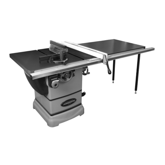
- Page 1 Operating Instructions and Parts Manual 10-inch Cabinet Saw Model PM1000 & PM1000T Powermatic 427 New Sanford Road LaVergne, Tennessee 37086 Part No. M-1791000 Ph.: 800-274-6848 Edition 3 04/2023 www.powermatic.com Copyright © 2015 Powermatic...
-
Page 2: Warranty And Service
1.0 Warranty and Service Powermatic warrants every product it sells against manufacturers’ defects. If one of our tools needs service or repair, please contact Technical Service by calling 1-800-274-6846, 8AM to 5PM CST, Monday through Friday. Warranty Period The general warranty lasts for the time period specified in the literature included with your product or on the official Powermatic branded website. -
Page 3: Table Of Contents
15.4.1 PM1000 Miter Gauge Assembly – Exploded View ................38 15.4.2 PM1000 Miter Gauge Assembly – Parts List ..................38 15.5.1 PM1000T Miter Gauge Assembly – Exploded View ................39 15.5.2 PM1000T Miter Gauge Assembly – Parts List ................... 40... -
Page 4: Safety Warnings
19. Keep visitors a safe distance from the work injury that may result from that use. area. Keep children away. 6. Model PM1000T has an industrial-grade low- 20. Make your workshop child proof with padlocks, friction corrosion-resistant coating on the table master switches or by removing safety keys. - Page 5 27. Keep hands clear of the blade area. Do not the table that can strike the operator. Kickback can reach past the blade to clear parts or scrap also result in the operator’s hands being pulled into with the saw blade running. Never saw the blade.
-
Page 6: About This Manual
Additional knowledge can be obtained from experienced users or trade articles. Whatever accepted methods are used, always make personal safety a priority. If there are questions or comments, please contact your local supplier or Powermatic. Powermatic can also be reached at our web site: www.powermatic.com. -
Page 7: Terminology
5.0 Terminology Arbor: Metal shaft that connects the drive Parallel: Position of the rip fence equal in distance mechanism to the blade. at every point to the side face of the saw blade. Bevel Edge Cut: Tilt of the saw arbor and blade Perpendicular: 90°... -
Page 8: Specifications
6.0 Specifications Model number ..........................PM1000 & PM1000T Stock Numbers: Saw unit only, without Accu-Fence or rail system ..................1791000 Saw with 30” Accu-Fence and rail system ....................1791000K Saw with 50” Accu-Fence and rail system ....................1791001K Saw unit only with industial-grade low-friction table coating, without Accu-Fence or rail system ....1791000T Saw with industial-grade low-friction table coating and 30”... - Page 9 L=length; W=width; D=depth; H=height The specifications in this manual were current at time of publication, but because of our policy of continuous improvement, Powermatic reserves the right to change specifications at any time and without prior notice, without incurring obligations.
-
Page 10: Setup And Assembly
– consult Accu-Fence manual. 7.3 Unpacking and Cleanup Model PM1000T industrial-grade low-friction corrosion-resistant coating on the table and table extensions. While the coating is durable, it can be damaged if metal or other hard and/or sharp objects... -
Page 11: Installing Handwheels And Hooks
Do not use solvents on plastic parts and avoid using an Figure 4 abrasive pad as it can scratch surfaces. Note: Model PM1000T has an industial-grade low- 2. Repeat for opposite extension. Lightly snug friction corrosion-resistant coating on the table screws. -
Page 12: Rails And Fence
NOTE: The switch bracket must be mounted to front rail before installing guide tube. Follow Refer to Figure 9. instructions in section 7.8, then install guide tube. Model PM1000T 7.8 Switch Bracket industrial-grade low-friction corrosion-resistant Refer to Figure 7. coating on the table and table extensions. -
Page 13: Instaling And Removing Blade
7.12 Installing and Removing Blade A blade is not provided with this machine. Model PM1000T industrial-grade low-friction corrosion-resistant Figure 11 (blade not provided) coating on the table and table extensions. While the coating is durable, it can be damaged 7.13 Riving Knife... -
Page 14: Anti-Kickback Pawls
3. Release button (J ). The transparent guard leaves (K) should drop freely to the table. 4. Lift up on guard assembly to verify proper seating. NOTE: The transparent leaves can be kept in raised position by lifting them up and forward. Guard and pawl assemblies must be securely installed, and leaves must be in contact with table, before beginning any... - Page 15 In the event of a malfunction or breakdown, qualified service personnel; and after reconnection, grounding provides a path of least resistance for the tool should comply with all local codes and electric current to reduce the risk of electric shock. ordinances.
-
Page 16: Adjustments
Figure 16 9.4 Miter Gauge Refer to Figures 17, 18, 18B, and 18C. For model PM1000T: The miter gauge has non-marring bottom surfaces to protect the industrial-grade low-friction table Figure 15 coating. To prevent damage to the table coating, only use the miter gauge supplied with this machine. - Page 17 (G). between bar and miter slot. Fence (model PM1000) Squaring Miter Gauge (model PM1000T): The Fence (D, Figure 17) can be adjusted by sliding to the right or left or removed entirely. 1. Place a square against miter gauge face, and against flat of blade.
-
Page 18: Blade Tilt Stop Adjustment
Figure 18B Adjusting Miter Gauge Angle Operations (model PM1000T, refer to Figure 18C): 1. Unscrew handle (D) just enough to loosen it. Figure 19 2. Press black tab (E) to release it from stop 0°. 4. Tilt blade with handwheel until square and 3. -
Page 19: Riving Knife Alignment
9.5.2 Tilt Stop 45° 4. Use a 3mm hex key to make adjustments to four set screws (D, Figure 25) accessible Repeat steps 1 through 4 above for 45° setting, as through openings located in the corners of the shown in Figure 22. Loosen nut (B ) with 11mm clamp plate (B, Figure 25). -
Page 20: Belt Adjustment
Refer to Figure 25. 1. Remove blade guard, pawl, table insert and riving knife. 2. Use a 5mm hex key to loosen two socket head button screws (E, Figure 25). Note: These screws are accessible through openings on the clamp plate (B) located diagonally on either side of the lever (A). -
Page 21: Arbor/Arbor Bearing Removal
10.0 Operation workpiece, resharpen all the points. Model PM1000T industrial-grade low-friction corrosion-resistant table coating. While the coating is durable, it can be damaged if metal or other hard and/or sharp objects strike, gouge, or scratch the surface. -
Page 22: Rip Sawing
through-sawing operations, cutoff and fence (B). Stand out of line with saw blade and workpiece to avoid sawdust and splinters coming section must NOT be confined. off the blade or a potential kickback. Always keep your hands out of line of the saw blade and never reach back of the If the work piece does not have a straight edge, cutting blade with either hand to hold the... -
Page 23: Resawing
Figure 35 Figure 34 10.4 Crosscutting Crosscutting is where the workpiece is fed cross When ripping long boards, use a support at front of grain into the saw blade using the miter gauge to table (C, Figure 34), such as a roller stand, and a support and position the workpiece (Figure 36). -
Page 24: Bevel And Miter Operations
Do not crosscut workpieces shorter than 6". Before starting a cut, be sure the miter gauge is securely clamped at the desired angle. Hold the workpiece firmly against the table and back against the miter gauge. Always use the saw guard and riving knife and make sure the riving knife is properly aligned. -
Page 25: Safety Devices
Figure 41 The process of cutting 1/8" to 13/16" grooves in workpieces is accomplished by the use of a stacked dado blade set or an adjustable type blade mounted on the saw arbor. By using various combinations of stacked dado blades, or properly setting the dial on an adjustable blade, an accurate width dado can be made. - Page 26 Push Stick and Push Block The use of a push block or push stick provides an added level of safety for the operator. A push stick is included with your table saw, but you may wish to make others personalized for different cutting procedures.
-
Page 27: Maintenance
Check all adjustments after lubricating. T-slots with a rust preventive. 12.3 Miscellaneous • Model PM1000T: Wipe down the table surface and T-slots. Always be aware of the condition of your machine. • Clean pitch and resin from the saw blade. -
Page 28: Optional Accessories
13.0 Optional Accessories These accessory items (purchased separately) can enhance the functionality of your table saw. Contact your dealer to order or call Powermatic at the phone number on the cover. Figure 46 # 708097 – Dado Insert Figure 47 # 708119 –... -
Page 29: Troubleshooting
14.0 Troubleshooting Table 2 Symptom Probable Cause Remedy Saw will not start. No incoming power. Check plug connection. Low voltage. Check power line for proper voltage. Open circuit motor loose Inspect all lead connections on motor for connection. loose or open connections. Cord damaged. -
Page 30: Replacement Parts
Number of your machine available when you call will allow us to serve you quickly and accurately. Non-proprietary parts, such as fasteners, can be found at local hardware stores, or may be ordered from Powermatic. Some parts are shown for reference only and may not be available individually. - Page 31 15.1.1 Table and Cabinet Assembly – Exploded View...
- Page 32 32 ....TS-0267021 ....Socket Set Screw ............ 1/4” x 1/2” ..... 6 33 ....PM1000-033 ....Extension Wing (for PM1000) ............... 2 ....PM1000-033T .... Extension Wing (for PM1000T) ..............2 34 ....TS-1550071 ....Flat Washer ............. M10 ......10 35 ....
-
Page 33: Motor And Trunnion Assembly - Exploded View
15.2.1 Motor and Trunnion Assembly – Exploded View... -
Page 34: Motor And Trunnion Assembly - Parts List
15.2.2 Motor and Trunnion Assembly – Parts List Index No Part No Description Size 101 .... PM1000-101 ....Arbor Nut ....................... 1 102 .... PM1000-102 ....Arbor Collar ....................1 104 .... PM1000-104 ....Arbor ......................1 105 .... - Page 35 Index No. Part No. Description Size 151 .... PM1000-151 ....Tilting Shaft ....................1 152 .... PM1000-152 ....Eccentric Bushing ..................1 153 .... TS-2342141 ....Hex Nut ..............M14 ....... 1 154 .... PM1000-154 ....Collar ......................2 155 ....
-
Page 36: Blade Guard Assembly - Exploded View
15.3.1 Blade Guard Assembly – Exploded View... -
Page 37: Blade Guard Assembly - Parts List
15.3.2 Blade Guard Assembly – Parts List Index No Part No Description Size 1 ....PM1000-301 ....Riving Knife ....................1 1A ....PM1000-301A .... Low Profile Riving Knife .......... 0.1” Thk ......1 1B ....1791793 ..... Low Profile Thin Kerf Riving Knife (Optional) ..0.079” Thk ....1 .... -
Page 38: Pm1000 Miter Gauge Assembly - Exploded View
15.4.1 PM1000 Miter Gauge Assembly – Exploded View 15.4.2 PM1000 Miter Gauge Assembly – Parts List Index No Part No Description Size 1 ....1791789 ..... Miter Gauge Assembly (index #2 thru 22) ............. 1 2 ....PM2000-340 ....Handle ......................1 3 .... -
Page 39: Pm1000T Miter Gauge Assembly - Exploded View
15.5.1 PM1000T Miter Gauge Assembly – Exploded View... -
Page 40: Pm1000T Miter Gauge Assembly - Parts List
15.5.2 PM1000T Miter Gauge Assembly – Parts List Index No Part No Description Size ....PM2000B-MGAT ..Miter Gauge Assembly (includes #1 thru 24) ..........1 1 ....PM1500-109T-01 ..Gauge Plate Locking Handle ................. 1 2 ....TS-1550061 ....Flat Washer ............. 8.5 x 23 x 2T ....1 3 .... -
Page 41: Electrical Connections
16.0 Electrical Connections... - Page 42 NOTES...
- Page 43 NOTES...
- Page 44 427 New Sanford Road LaVergne, Tennessee 37086 Phone: 800-274-6848 www.powermatic.com...
Need help?
Do you have a question about the PM1000T and is the answer not in the manual?
Questions and answers