Table of Contents
Advertisement
Quick Links
La Marche Manufacturing Company
www.lamarchemfg.com
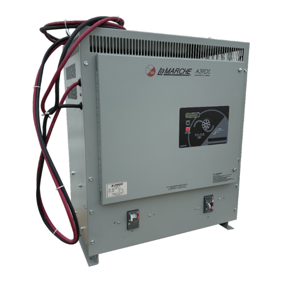
A39DS
Universal Filtered Battery Charger
This manual is subject to change without notice. You may obtain the newest version of the manual at www.lamarchemfg.com
106 Bradrock Dr. Des Plaines 60018-1967
Tel: 847 299 1188
Fax: 847 299 3061
Installation and Operation Manual
CPN 148973
Instruction Drawing Number: P25-LA39DS-1
Revision A00
Rev. Date: 10/23
1
ECN: 23419
Advertisement
Table of Contents

Related Manuals for La Marche A39DS


Summary of Contents for La Marche A39DS
- Page 1 La Marche Manufacturing Company www.lamarchemfg.com A39DS Universal Filtered Battery Charger Installation and Operation Manual This manual is subject to change without notice. You may obtain the newest version of the manual at www.lamarchemfg.com 106 Bradrock Dr. Des Plaines 60018-1967 Instruction Drawing Number: P25-LA39DS-1...
-
Page 2: Electrical Safety
Important Safety Instructions Before using this equipment read all manuals and other documents related to this charger and other equipment connected to this charger. Always have a copy of a charger’s manual on file nearby in a safe place; if a replacement copy of a manual is needed, it can be found at www.lamarchemfg.com. -
Page 3: Charger Location
If any damage is observed, take pictures and contact the carrier immediately to file a damage claim. Contact La Marche for a Return Material Authorization number to have the charger sent back for evaluation and repair. -
Page 4: Table Of Contents
Moving the A39DS ........................3 Installation ........................... 4 Mounting the A39DS ........................4 2.1.1 Wall-Mounting the A39DS (#6 Enclosure Only) ................5 2.1.2 Floor-Mounting the A39DS (All Enclosures) ................. 6 AC Input Connections ........................6 DC Output Connections ......................... 8 Alarms ............................ - Page 5 DC Voltage Setting ......................... 13 DC Current Limit Setting ......................... 13 Elapsed Time ..........................13 4.1.2 Alarm Settings ........................13 4.1.3 Advanced Settings ........................14 Shutoff Enable ..........................14 AC Volts Scale ..........................14 Security ............................14 Firmware Menu ..........................14 Firmware Version ..........................
-
Page 6: Model Scope/General Description
10% of the rated output and the charger timer defaults to 8 hours on start-up. The A39DS will “Auto” start upon connection of the battery and “Auto” stop when the charge cycle is terminated or a normal charge is complete. -
Page 7: Quick Start Guide
A39DS Quick Start Guide La Marche A39DS Battery Charger: Getting Started Please read the Important Safety Instructions before proceeding. Make sure to check WARNING: for any shipping damages before getting started. 1 – Connect Proper AC Voltage Confirm & connect proper AC voltage against charger nameplate. If charger is multi-tap, refer to AC Input Voltage Tap Configuration table inside the charger or on charger schematic. -
Page 8: Equipment Handling
Storing the A39DS If the A39DS is to be stored for more than a few days after delivery, it should be stored within its shipping container. The location chosen for storage should be within an ambient temperature of -40 to 185° F (-40 to 85°... -
Page 9: Installation
Verify the method of mounting and the weight of the A39DS, using Tables 1, 2, and 3. The following considerations should be taken: •... -
Page 10: Wall-Mounting The A39Ds (#6 Enclosure Only)
Wall-Mount Procedure To wall-mount the A39DS, install five 5/16 in (8 mm) bolts on the wall rated to support the charger weight plus a safety factor of at least two times. Secure the charger on bolts, add appropriate mounting hardware, and tighten securely. -
Page 11: Floor-Mounting The A39Ds (All Enclosures)
Floor-Mounting Procedure To floor-mount the A39DS, install four to six bolts into the floor. Place the charger on the bolts, add appropriate mounting hardware onto the floor-mounting anchor bolts, and tighten securely. Refer to Figure 2 for hardware specifications and floor-mounting dimensions. -
Page 12: Ac Input Connections
Table 4 – AC/DC & Ground Wire Size Minimum Requirements (All wires specified in the table are rated at 90 °C or 194 °F) NOTE: These are recommended sizes per La Marche Standards. The National Electrical Code (NEC) and Local Wiring Codes must be followed. -
Page 13: Dc Output Connections
´ MaxAmp ´ NOTE: These are recommended sizes per La Marche Standards. The National Electrical Code (NEC) and Local Wiring Codes must be followed. DC Connection Procedure To prevent the DC circuit breaker from tripping when connecting the battery, connections should be done in the following order. -
Page 14: Alarms
Alarms As a standard feature of the A39DS, there are multiple alarms available that will be displayed on the LCD during an event. A “Failure” LED is illuminated if any the following alarms occur: • AC Failure • High AC Input Voltage •... -
Page 15: Operation
Starting the A39DS All equipment is shipped from the factory fully checked and adjusted based on the model number. 3.1.1 Checking the Installation Before attempting to start up the A39DS, check and verify the following: • Verify all connections are correct. •... -
Page 16: Digital Control Board
Digital Control Board The standard A39DS comes with an LCD digital control board. The digital control board is a more attractive and user-friendly option, with many additional features. Figure 3 – A39DS Front Panel The parameters viewable on the idle display are as follows: Standard A39DS Display Sequence Voltage 132.3 V... -
Page 17: Output Voltage Adjustments
Output Voltage Adjustments The output voltage of the A39DS charger is set to a default value of 10% above the battery voltage. But should be adjusted to meet the battery manufacturer recommendations. To adjust the DC output voltage, refer to Section 4.1.1. -
Page 18: Output Settings
Low DC Current >Alarm Settings Low DC Current à Alarm 0.5 A NOTE: Alarm threshold defaults are based on the charger rating. The alarm threshold values shown above are not representative of the default values for any specific A39DS charger. -
Page 19: Advanced Settings
The menu allows the user to view the current firmware version of the charger. Update Firmware The A39DS firmware can be updated, as a standard feature, via a microSD card. To update the firmware, follow the procedure below: NOTE: If more than one firmware .bin file is on the microSD card, the bootloader will not program or reprogram the flash and will show a message saying “More than 1 file found!”... -
Page 20: Lcd Settings
The “Serial Number” setting allows the user to change the serial number associated with the S2A-368S board. This serial number is the serial number of the A39DS charger and is set at the factory for new chargers. If a user receives a replacement S2A-368S board, the serial number will have to be set via calibration. -
Page 21: Basic Defaults
Test LEDs The “Test LEDs” menu allows the user to run a basic lamp test on the A39DS. After selecting this menu, press the “ENTER” button to light all the LEDs on the display membrane. To end the LED test, press back. -
Page 22: Service
Before working inside the A39DS, ensure the AC power is off at the main breaker box and the battery has been removed from the charger’s DC output terminals, either by removing the battery cables or exercising the battery disconnect. -
Page 23: Troubleshooting Procedure
La Marche Phone Number: (847) 299-1188 Ordering Replacement Parts Contact La Marche to place an order for spare or replacement parts. To order replacement parts; please provide the model and serial number of the battery charger, the part needed, and the quantity required. -
Page 24: Troubleshooting Chart
Service Department for further troubleshooting. Ordering Replacement Parts Contact La Marche to place an order for spare or replacement parts. To order replacement parts; please provide the model and serial number of the charger, the part needed, and the quantity required. - Page 25 Appendix A: A39DS Menu Structure Flowchart MENU Button Settings Menu Output Settings DC Voltage 2-30 (30V) 6-60 (60V) 8-90 (90V) 12-150 (150V) DC Current 5-100% Elapsed Time 1-99 hours Alarm Settings Low DC Current Advanced AC Volts Scale 110-600 Security...
- Page 26 Appendix B: A39DS Specifications ELECTRICAL AC Input 120, 208, 240, or 480VAC Voltage range +10% / -12% Frequency Range 50Hz or 60Hz ± 5% DC Output 20 - 200 ADC 30, 60, 90 or 150VDC Output Filtering 30, 60VDC - 30mV RMS, with battery 90, 150VDC - 100mV RMS, with battery ±...
- Page 27 480 VAC – 3 PH. A39DS-200-60V-C3 6 – 60 480 VAC – 3 PH. A39DS-60-90V-BD1 8 - 90 240/208 VAC – 1 PH A39DS-100-90V- BD3 8 - 90 240/208 VAC – 3 PH. A39DS-150-90V-BD3 8 - 90 240/208 VAC – 3 PH. A39DS-200-90V-BD3 8 - 90 240/208 VAC –...
- Page 28 Appendix D: Document Control and Revision History Part Number: 148973 Instruction Number: P25-LA39DS-1 Issue ECN: 23419 – 10/23...
Need help?
Do you have a question about the A39DS and is the answer not in the manual?
Questions and answers