Table of Contents
Advertisement
Quick Links
RS605
5 x 60W Slave Amplifier
Item ref: 953.151UK
User Manual
Introduction
Thank you for choosing the Adastra RS605 rackmount 5 x 60W slave amplifier as part of your public
address system. This amplifier is designed to offer high quality, dependable service for mobile and
installed systems. Please read this manual fully and follow the instructions to achieve the best results
with your new purchase and to avoid damage through misuse.
Advertisement
Table of Contents

Related Manuals for Adastra RS605


Summary of Contents for Adastra RS605
- Page 1 User Manual Introduction Thank you for choosing the Adastra RS605 rackmount 5 x 60W slave amplifier as part of your public address system. This amplifier is designed to offer high quality, dependable service for mobile and installed systems. Please read this manual fully and follow the instructions to achieve the best results...
- Page 2 Caution: Please read this manual carefully before operating Damage caused by misuse is not covered by the warranty SAFETY SYMBOL AND MESSAGE CONVENTIONS CAUTION AVIS RISK OF ELECTRIC SHOCK RISQUE DE CHOC ELECTRIQUE NE PAS DO NOT OPEN OUVRIR This symbol indicates that dangerous voltage constituting a risk of electric shock is present within this unit This symbol indicates that there are important operating and maintenance instructions in the literature accompanying this unit.
-
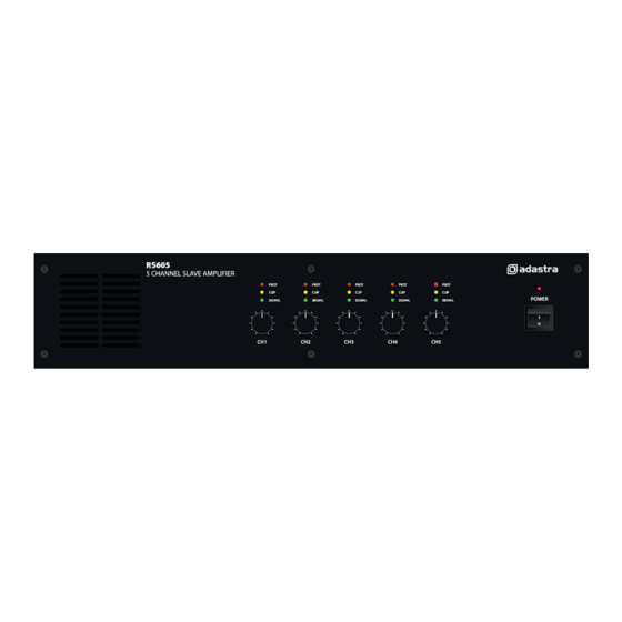
Page 3: Front Panel
Front panel PROTECT LED indicators CLIP LED indicators SIGNAL LED indicators Channel volume controls Power on/off switch Rear panel Mains voltage selector IEC mains inlet & fuse holder 24Vdc power connection Mode switch 10. Speaker output modular connectors 11. Channel GAIN controls 12. -
Page 4: Connection And Setup
Ensure the POWER (5) is switched off until all input and speaker connections are in place. The RS605 is designed to accept up to 5 line inputs from a mixer or multiple input sources and provide power for up to 5 independent speaker zones from its 5 internal amplifiers. -
Page 5: Low Impedance Systems
Low impedance systems Alternatively, each of the RS605 amplifiers can provide an output for a single 8Ω speaker by connecting the “8Ω” output to the positive (+) speaker connection and “COM” output to the negative (-) speaker connection. It is important to ensure that the speaker load is no less than 8Ω and that the power handling of the speaker is equal to or greater than the output power of the amplifier. -
Page 6: Operation
Operation Select the required operating mode from the MODE switch on the rear panel (9). If the preferred usage is for all outputs to have the same signal, the MIX mode may be used, allowing 5 inputs to all 5 amplifiers. Otherwise, the 5CH mode feeds each input independently to its relative amplifier. As a start point, set all the GAIN (11) controls on the rear panel to the 12 o’clock position. -
Page 7: Specifications
Specifications Power supply 110/230Vac, 50/60Hz DC power 24Vdc screw terminals Fuse T5A (250V) Output power 300Wrms (5 x 60W, all channels driven) Output connections 5 x modular terminals (COM/8 Ohms/100V) Input connections 5 x paired RCA line Input sensitivity -10dBV Frequency response 100Hz-20kHz T.H.D. -
Page 8: Troubleshooting
Troubleshooting Ensure IEC lead is in good condition and connected properly No power LED on control panel If 24Vdc power input is being used, check battery is charged Ensure POWER switch is on and check mains inlet fuse Check input signals and condition of input connection leads Check that the correct operation mode has been selected (MIX/5CH) Power LED is on but no other LEDs and no output...
Need help?
Do you have a question about the RS605 and is the answer not in the manual?
Questions and answers