Advertisement
Quick Links
The Intelligent Solution
Features
Providing two tones.
Using several ultra-high brightness (UHB) red LEDs as
light source.
Loop powered, low consumption.
Polarity-insensitive signal cables.
Complies with EN 54-3.
Description
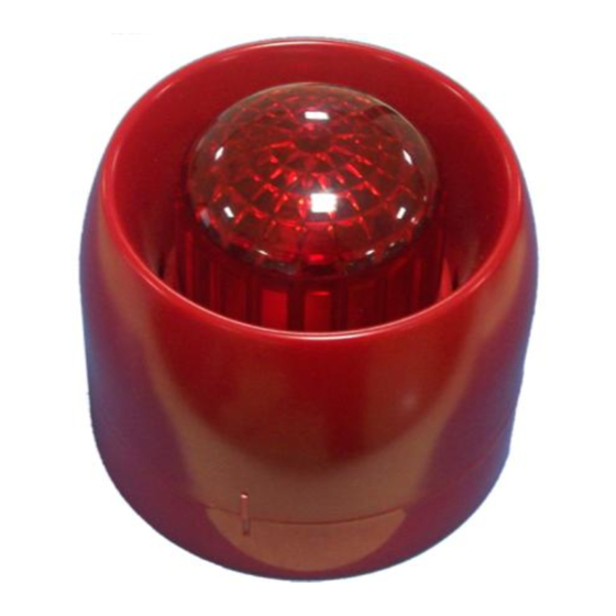
I-9407 Intelligent Sounder Strobe is a kind of audible and
visual alarm device installed in field, which can be initiated by
fire alarm control panel in fire control center to generate
strong audible and visual alarm signal warning people to
evacuate.
Both 25.5mm shallow base and 40mm deep base are
available. Unless otherwise specified, illustrations in this
manual refer to the shallow base.
Connection & Wiring
Terminals on the base are shown in Fig. 2.
Arch knockout hole
Fig. 1
Z1 (2), Z2 (4): To the loop of control panel,
polarity-insensitive.
Recommended Wiring
2
1.0mm
or above fire cable, subject to local codes.
Installation
The
sounder
strobe
recommended to be installed 0.2m from the ceiling if the
height of the space is normal. Fig. 2 shows the mounting
hole spacing and mounting direction.
If the conduit is embedded in the wall, the base can be
mounted on the electrical box. In this case, both deep
and shallow bases can be used. Refer to Fig. 3a and
3b.
If the conduit is surface mounted, then only the deep
base can be used and the conduit is to be installed
through the knockout hole. Refer to Fig. 4.
The base and the sounder strobe are twisted together.
When mounting, remove the sounder strobe, thread
cables through cable entry in the base and connect with
corresponding terminals, then twist the sounder strobe
onto the base.
If the sounder strobe is required to be tamper resistant,
knock down the arch knockout hole as shown in Fig. 1
and fasten it with the base using ST2.9×6.5 tapping
screws (in this case, it has to be removed with special
tools).
30307189
Fig. 2
is
surface
mounted.
Intelligent Sounder Strobe
Conduit
Electrical Box
Conduit
Electrical Box
It's
Application
The address of the sounder can be programmed using a
programmer. Refer to P-9910B Hand Held Programmer
Installation and Operation Manual for details.
The
sounder
addresses when its device type is 121. It occupies one
address when its device type is other numbers (factory
default is 27).
I-9407
Knock-out Hole
Sounder Strobe
Fig. 3a (deep base)
Sounder Strobe
Fig. 3b
Conduit
Sounder Strobe
Fig. 4 (deep base)
strobe
occupies
two
consecutive
Issue 1.02
Advertisement

Related Manuals for GST I-9407


Summary of Contents for GST I-9407
- Page 1 Complies with EN 54-3. Description I-9407 Intelligent Sounder Strobe is a kind of audible and visual alarm device installed in field, which can be initiated by fire alarm control panel in fire control center to generate strong audible and visual alarm signal warning people to evacuate.
- Page 2 Programmer products not covered by this warranty. C-94DB Base Supplied Separately This document is subject to change without notice. Please contact GST for more information or questions. GST China GST UK GST Dubai Gulf Security Technology Co., Ltd. Global System Technology PLC Global System Technology PLC No.
Need help?
Do you have a question about the I-9407 and is the answer not in the manual?
Questions and answers