Advertisement
Quick Links
Features
Providing 16 tones.
Using ultra bright LEDs as source for light
indication. Optional transparent colorless lens
(C-94WL) available.
Loop powered or external 24V powered.
Power-saving consumption mode and normal
consumption mode (factory default).
Single/dual address programmable.
Working modes: sounder & strobe / strobe only /
sounder only.
Standard: EN 54-3.
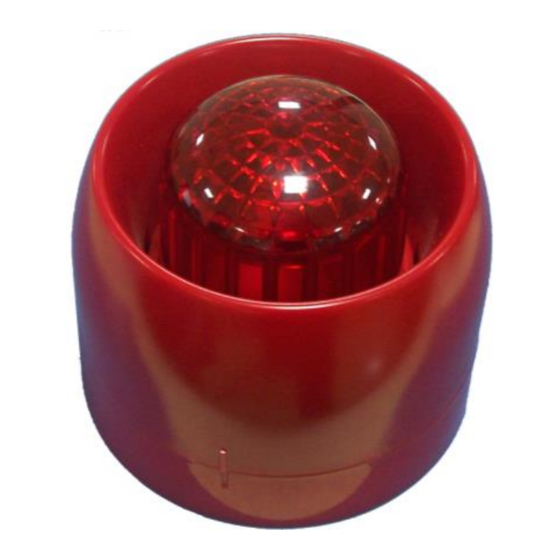
Description
I-9403 Intelligent Sounder Strobe is an audible and
visual alarm device installed in field, which can be
activated by fire alarm control panel in fire control
center. After activated, it will generate strong audible
and visual alarm signal to warn people in field.
A 25.5mm high shallow base and a 40mm high deep
base are available. The sounder strobe comes with
the shallow base. The deep base C-94DB should be
ordered separately. Unless otherwise stated, all
descriptions in this manual take the shallow base as
example.
Connection & Cabling
Terminals on the base are shown in Fig. 2.
Tamper-proof
knockout
Drain Hole
?
110
Fig.1
Z1 (2), Z2 (4): Loop of the control panel, polarity-
insensitive.
D1 (9), D2 (7): To external 24VDC power, polarity-
insensitive.
Recommended Wiring
2
1.5mm
or above fire cable for D1, D2, Z1 and Z2,
subject to local codes.
Installation
When surface mounted, the sounder strobe should
be placed 0.2m from the ceiling for normal space
height. When the conduit is embedded, the base
can be mounted on the back box. When the
conduit is surface mounted, the deep base should
be adopted. Knock the knockout hole, and connect
the conduit with it. The mounting hole spacing and
mounting direction are shown in Fig. 2. Mounting
method is shown in Fig. 3a and Fig. 4. The conduit
must be embedded when the shallow base is used,
as shown in Fig. 3b.
The base and the sounder strobe are twisted
together. When mounting, remove the sounder
strobe, thread cables through the cable entry in the
base and connect with corresponding terminals,
then twist the sounder strobe onto the base.
30312237
Intelligent Sounder Strobe
Arrow Upward
Fig. 2
If the sounder strobe is required to be tamper-proof,
knock down the arch knockout as shown in Fig. 1
and fix it with ST2.9×6.5 self-tapping screws (in
this case, it can only be removed by a cross
screwdriver).
Application
Address, tone, programming method, working mode,
consumption mode can be set through P-9910B
programmer.
Page 1
I-9403
Knockout
Conduit
Back Box
Fig. 3a
Fig. 3b
Conduit
Sounder Strobe
Fig. 4
548e/02
2831-CPR-F2358
GST-0003-01
07
Sounder Strobe
Issue 1.07
Advertisement

Subscribe to Our Youtube Channel
Related Manuals for GST I-9403


Summary of Contents for GST I-9403
- Page 1 Standard: EN 54-3. 2831-CPR-F2358 GST-0003-01 Description I-9403 Intelligent Sounder Strobe is an audible and visual alarm device installed in field, which can be activated by fire alarm control panel in fire control Knockout center. After activated, it will generate strong audible...
- Page 2 Tone, single/dual address mode and consumption Sound Level mode can be set with the same method as Para- Address Consump- Tone 1m Ahead/24V programming the parameter of a module by meter Setting tion mode (dB) P-9910B programmer. Refer to Table 1 for parameters P-9910B Installation...
- Page 3 Programmer Humanity Enclosure Limited Warranty Material ф110mm×110.4mm (deep base) Dimension GST warrants that the product will be free from defects ф110mm×95.9mm (shallow base) (D×H) in design, materials and workmanship during the Mounting Hole 55mm~80mm warranty period. This warranty shall not apply to any...
- Page 4 72.6 71.8 72.1 This Data Sheet is subject to change without notice. Please contact GST for more information or questions. Gulf Security Technology Co., Ltd. No. 80, Changjiang East Road, QETDZ, Qinhuangdao, Hebei, P. R. China 066004 Tel: +86 (0) 335 8502434 Fax: +86 (0) 335 8502532 service.gst@fs.utc.com www.gst.com.cn...
Need help?
Do you have a question about the I-9403 and is the answer not in the manual?
Questions and answers