Advertisement
Quick Links
SIMEX Ltd., Wielopole 11, 80-556 Gdańsk, Poland,
tel. (+48) 58 762-07-77, www.simex.pl
Operating Manual
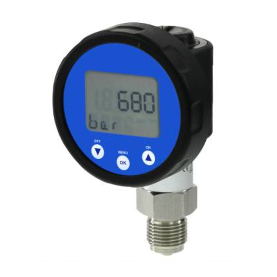
Digital Pressure Gauge
CCM-P-02, CCM-P-02P, CCM-K-05, CCM-P-05P
READ THOROUGHLY BE FORE USING THE DEVICE
KEEP FOR FUTURE REFERENCE
Version
: CCM-P-02_05_INSSXEN_v.1.00.000
:
1. General and safety-related information on
this operating manual
This operating manual enables safe and proper handling of the
product, and forms part of the device. It should be kept in close
proximity to the place of use, accessible for staff members at
any time.
All persons entrusted with the mounting, installation, putting into
service, operation, maintenance, removal from service, and
disposal of the device must have read and understood the
operating manual and in particular the safety-related information.
Complementary to this operating manual the current data
sheet has to be adhered to.
Download the data sheet by accessing www.simex.pl or
request it: info@simex.pl | phone: +48 58 7620777
In addition, the applicable accident prevention regulations,
safety requirements, and country-specific installation standards
as well as the accepted engineering standards must be
observed.
1.1 Symbols used
-
Type and source of danger
-
Measures to avoid the danger
Warning word
Warning word
Meaning
-
Imminent danger!
-
Non-compliance will result in
DANGER
death or serious injury.
-
Possible danger!
-
Non-compliance may result in
death or serious injury.
WARNING
-
Hazardous situation!
-
Non-compliance may result in
minor or moderate injury.
CAUTION
NOTE
- draws attention to a possibly hazardous situation that
may result in property damage in case of non-compliance.
ü
Precondition of an action
1.2 Staff qualification
Qualified persons are persons that are familiar with the
mounting, installation, putting into service, operation,
maintenance, removal from service, and disposal of the product
and have the appropriate qualification for their activity.
This includes persons that meet at least one of the following
three requirements:
-
They know the safety concepts of metrology and
automation technology and are familiar therewith as
project staff.
-
They are operating staff of the measuring and
automation systems and have been instructed in the
handling of the systems. They are familiar with the
operation of the devices and technologies described in
this documentation.
-
They are operating staff of the measuring and
automation systems and have been instructed in the
handling of the systems. They are familiar with the
operation of the devices and technologies described in
this documentation.
All work with this product must be carried out by qualified
persons!
1.3 Intended use
The above-mentioned digital pressure gauges are intended for
on-site display of the applied system pressure. It has to be used
only for this purpose, considering the following information. The
display housing is rotatable, thus ensuring an easy reading even
under unfavourable mounting conditions.
Devices with EHEDG certified process connection have been
developed especially for applications in food and pharmaceutical
industry. The process connection is hygienic and can be
sterilized.
Permissible measuring and cleaning media are gases or liquids,
which are compatible with the media wetted parts of the device
(according to data sheet) and your system. This must be
ensured for the application.
The user must check whether the device is suited for the
selected use. In case of doubt, please contact our sales
department: info@simex.pl | phone: +48 58 7620777
Manufacturer assumes no liability for any wrong selection and
the consequences thereof!
The technical data listed in the current data sheet are engaging
and must absolutely be complied with. If the data sheet is not
available, please order or download it from our homepage:
http://www.simex.pl
1.4 Incorrect use
Danger through incorrect use
- Only use the device in permissible
media and in accordance with its
intended use.
- Do not use the device as a ladder or
climbing aid.
WARNING
- The device must not be altered or
modified in any way.
- Simex is not liable for damage
caused by improper or incorrect use.
1.5 Limitation of liability and warranty
Failure to observe the instructions or technical regulations,
improper use and use not as intended, and alteration of or
damage to the device will result in the forfeiture of warranty
and liability claims.
1.6 Safe handling
NOTE -
Do not use any force when installing the device to
prevent damage of the device and the plant!
NOTE -
Treat the device with care both in the packed and
unpacked condition!
NOTE -
Do not throw or drop the device!
NOTE -
Excessive dust accumulation and complete coverage
with dust must be prevented!
NOTE -
The device is state-of-the-art and is operationally
reliable. Residual hazards may originate from the device if it is
used or operated improperly.
1.7 Scope of delivery
Check that all parts listed in the scope of delivery are included
free of damage, and have been delivered according to your
purchase order:
- digital pressure gauge
- mounting instruction
1.8 UL approval (for devices with UL marking)
The UL approval was effected by applying the US standards,
which also conform to the applicable Canadian standards on
safety.
Observe the following points so that the device meets the
requirements of the UL approval:
- only indoor usage
- maximum operating voltage: according to data sheet
- use only batteries with UL certification
2. Product identification
The device can be identified by its manufacturing label. It
provides the most important data. By the ordering code the
product can be clearly identified. For identification of the
firmware the program version will appear for about 1 second in
the display after starting up the device. Please hold it ready for
inquiry calls.
type designation
ordering code
serial number
SIMEX Sp. z o.o., 80-556 Gdańsk, ul. Wielopole 11
Poland, tel. (+48 58) 762-07-77, www.simex.pl
CCM-P-02
M0E-4003-0-B2-0K0-400-1-1-1-1-000
SN: 12345678
Input: 0 ... 400 bar gauge
Battery: 2 x 3,6V 1/2 AA Li
Fig. 1 Example of manufacturing label
NOTE
-
The manufacturing labels must not be removed!
3. Mounting
3.1 Mounting and safety instructions
Danger of death from airborne parts,
leaking fluid, electric shock
-
Always mount the device in a
DANGER
depressurized condition!
Danger of death from improper
installation
-
This device may only be installed by
qualified technical personnel who has
WARNING
read and understood the operating
manual!
NOTE -
Handle this electronic precision measuring device
carefully in packed as well as in unpacked condition!
NOTE -
Handle the unprotected diaphragm very carefully - it is
very sensitive and may be easily damaged.
NOTE -
The device may not be thrown
!
NOTE
- Do not remove the packaging or protective caps of the
device until shortly before the mounting procedure, in order to
exclude any damage to the diaphragm and the thread!
Protective caps must be kept! Dispose of the packaging
properly!
NOTE -
Place the protective cap on the pressure port again
immediately after disassembling.
NOTE -
In hydraulic systems, position the device in such a
way that the pressure port points upward (venting).
NOTE -
Provide a cooling line when using the device in steam
lines.
NOTE
- When installing the device, avoid high mechanical
stresses on the pressure port! This will result in a shift of the
characteristic curve or to damage, in particular at very small
pressure ranges.
NOTE
- The permissible tightening torque depends on the
conditions on site (material and geometry of the mounting point).
The specified tightening torques for the digital pressure gauge
must not be exceeded!
NOTE
- The display and the plastic housing are equipped with
rotational limiters. Do only rotate the display or the housing
within the limit.
NOTES -
for mounting outdoors or in a moist
environment:
- Please note that your application does not show a dew point,
which causes condensation and can damage the device.
There are specially protected devices for these operating
conditions. Please contact us in such case.
- Select the mounting position such that splashed and
condensed water can drain off. Stationary liquid on sealing
surfaces must be excluded!
- Mount the device such that it is protected from direct solar
radiation. In the most unfavourable case, direct solar radiation
leads to the exceeding of the permissible operating
temperature.
- A device with gauge reference in the housing (small hole next
to the electrical connection) must be mounted such that the
gauge reference is protected against dirt and humidity. If the
device is exposed to liquid admission, the gauge reference
will be blocked, and the equalization of air pressure will be
prevented. In this condition, a precise measurement is
impossible and damage to the device may occur.
3.2 Conditions for devices with EHEDG certificate
Install the device according to the requirements given in EHEDG
Guidelines 8, 10 and 37. That is to mount the device in a self-
draining orientation. The device should be installed flush to the
process area. If mounting in a T-piece, the ratio between the
depth of the upstand (L) and the diameter (D) of the upstand
shall be L/D<1. If welded adapters are used, the food contact
surface must be smooth, and the welding has to be done
according to EHEDG Guideline 9 and 35. Suitable pipe
couplings and process connections must be applied according to
the EHEDG Position Paper. (List the available ones.)
3.3 Mounting steps for connections according
to DIN 3852
NOTE -
Do not use any additional sealing material such as
yarn, hemp or Teflon tape!
ü
The O-ring is undamaged and seated in the designated
groove.
ü
The sealing face of the mating component has a flawless
surface. (R
3.2)
Z
1
Screw the device into the corresponding thread by hand.
2
Devices equipped with a knurled ring:
only tighten by hand
3
Devices with a spanner flat made of steel must be tightened
using a suitable open-end wrench. Permissible tightening
torques for digital pressure gauge:
G1/4":
approx. 5 Nm
G1/2": approx. 10 Nm
G3/4":
approx. 15 Nm
G1":
approx. 20 Nm
G1 1/2": approx. 25 Nm
3.4 Mounting steps for connections according
to EN 837
ü
A suitable seal for the medium and the pressure to be
measured is available. (e.g. a copper seal)
ü
The sealing face of the mating component has a flawless
surface. (R
6.3)
Z
1
Screw the device into the corresponding thread by hand.
2
Then tighten it using an open-end wrench. Permissible
tightening torques for digital pressure gauge:
G1/4": approx. 20 Nm
G1/2": approx. 50 Nm
NOTE
– note the permitted pressure according to EN 837:
G1/4"
Counterpart has to be of
p ≤ 600 bar
EN 837
steel according to
DIN 17440 with strength
G1/2"
p ≤ 1000 bar
R
0.2 ≥ 190 N/mm
EN 837
p
G1/4"
p > 600 bar,
Counterpart has to be of
EN 837
p ≤ 1000 bar
steel according to
DIN 17440 with strength
G1/2"
p > 1000 bar,
R
0.2 ≥ 260 N/mm
EN 837
p ≤ 1600 bar
p
NOTE
- Please refer to data sheet or contact sales department
at Simex regarding max. permitted pressure of device.
3.5 Mounting steps for NPT connections
ü
Suitable fluid-compatible sealing material, e.g. PTFE tape,
is available.
1
Screw the device into the corresponding thread by hand
2
Then tighten it using an open-end wrench. Permissible
tightening torques for digital pressure gauge:
1/4" NPT: approx. 30 Nm; 1/2 " NPT: approx. 70 Nm
3.6 Mounting steps for dairy pipe connections
ü
The O-ring is undamaged and seated in the designated
groove.
ü
Chapter "3.2" have been noticed.
EHEDG conformity is only ensured in combination with
an approved seal for codes M73, M75, M76. This is e.g.:
ASEPTO-STAR k-flex upgrade seal by Kieselmann GmbH
1
Centre the dairy pipe connection in the counterpart.
2
Screw the cup nut onto the mounting part.
3
Then tighten it using a hook wrench.
3.7 Mounting steps for Clamp and Varivent
â
connections
ü
A suitable seal for the measured fluid and the pressure to
be measured is available.
ü
Chapter "3.2" have been noticed.
EHEDG conformity is only ensured in combination with
an approved seal. This is e.g.:
for Clamp connections - codes C61, C62, C63:
T-ring seal from Combifit International B.V.
â
for Varivent
connections - codes P40, P41:
EPDM-O-ring which is FDA-listed
Note, that P40 can only be used for tank flanges.
1
Place the seal onto the corresponding mounting part.
â
2
Centre the clamp connection or Varivent
connection
above the counterpart with seal.
3
Then fit the device with a suitable fastening element
(e. g. semi-ring or retractable ring clamp) according to
the supplier's instructions.
3.8 Mounting steps for flange connections
ü
A suitable seal for the measured fluid and the pressure to
be measured is available. (e.g. a fiber seal)
1
Put the seal between connecting flange and counter flange
2
Install the device with 4 resp. 8 screws (depending on
flange version) on the counter flange.
3.9 Positioning of the display module
In order to ensure easy readability even when the device is
installed in an awkward location, the display can be rotated into
the desired position. Its rotational capability is illustrated below.
Note rotation limits.
Fig. 2 Rotatability
4. Supply / changing the batteries
The digital pressure gauge is supplied by two 3.6 V-lithium-
batteries (type 1/2 AA). Stored values/parameters are also kept
after changing the batteries.
If the symbol for low batteries is indicated in the display, it is
necessary to replace them as soon as possible with two new
ones of the same type in order to ensure a good readability of
the values.
The battery case is located under the black, circular plastic cap
on the top of the housing.
plastic cap above battery case
Fig. 3 Battery case
To change the batteries, go ahead as follows - this has only to
be done in switched-off condition.
1
turn the plastic cap 45° anti clockwise by a coin
(e.g. 2 € coin) as far as possible
2
hold the count tight and lever the plastic cap out of
the housing with help of the count
3
take the cap off and change the batteries
4
lock the device properly
NOTE -
An incorrect usage may cause a leak out of
batteries and so a damage the device!
NOTE -
Never combine batteries of different types or old
with new ones!
NOTE -
Make sure that the batteries are connected
correctly with the corresponding contacts in the battery
case.
NOTE -
Never try to charge batteries, demount them, or
short-circuit them.
NOTE -
Keep the batteries away from heat and unshielded
flame.
5. Commissioning
Danger of death from airborne parts,
leaking fluid, electric shock
-
Operate the device only within the
DANGER
specification! (according to data sheet)
2
ü
The device has been installed properly.
ü
The device does not have any visible defect.
2
6. Operation
6.1 Control and display elements
limit exceeding
neg. / pos.
symbol
for indicate
low batteries
operating buttons
Fig. 4 Touch pad
The indication of the measured value as well as the
configuration of the individual parameters occurs menu-driven
via the LC display. The individual functions can be set with the
help of three miniature push buttons located in the front.
The menu system is a closed system allowing you to scroll both
forward and backward through the individual set-up menus to
navigate to the desired setting item. All settings are permanently
stored in an EEPROM and therefore available again even after a
battery change.
Button functions
switch the device on
in operating mode:
- move forward in the menu system
- increase the displayed value
switch the device off
in operating mode:
- move backwards in the menu system
- reduce the displayed value
enter operating mode
in operating mode:
OK
- select the individual menu item
- confirm the set value
measured value
unit
Advertisement

Related Manuals for Simex CCM-P-02


Summary of Contents for Simex CCM-P-02
- Page 1 - Please refer to data sheet or contact sales department Warning word Meaning at Simex regarding max. permitted pressure of device. SIMEX Sp. z o.o., 80-556 Gdańsk, ul. Wielopole 11 limit exceeding Poland, tel. (+48 58) 762-07-77, www.simex.pl neg. / pos.
- Page 2 Download these by accessing www.simex.pl 0.1 bar is necessary _________________________________________________________________ or request them: info@simex.pl | phone: +48 58 7620777 If the re-calibration leads to a worsening _________________________________________________________________ of the original calibration, e. g. as a In case of doubt regarding the fluid used, devices without a...
Need help?
Do you have a question about the CCM-P-02 and is the answer not in the manual?
Questions and answers