Table of Contents
Advertisement
Quick Links
ion Splicer
Technical Support and E-Warranty Certificate
OPTICAL FIBER FUSION SPLICER
We continue to be committed to provide you tools with
competitive price. "Save Half", "Half Price" or any other similar
expressions used by us only represents an estimate of savings
you might benefit from buying certain tools with us compared
to the major top brands and doses not necessarily mean to
cover all categories of tools offered by us. You are kindly
reminded to verify carefully when you are placing an order with
us if you are actually saving half in comparison with the top
User Manual
www.vevor.com/support
USR MANUAL
Model: ALK-T1
major brands.
Advertisement
Table of Contents

Related Manuals for VEVOR ALK-T1


Summary of Contents for VEVOR ALK-T1
- Page 1 Technical Support and E-Warranty Certificate www.vevor.com/support OPTICAL FIBER FUSION SPLICER USR MANUAL Model: ALK-T1 We continue to be committed to provide you tools with competitive price. "Save Half", "Half Price" or any other similar expressions used by us only represents an estimate of savings...
- Page 2 This is the original instruction, please read all manual instructions carefully before operating. VEVOR reserves clear interpretation of our user manual. The appearance of the product shall be subject to the product you received. Please forgive us that we won't inform you again if there are any technology or software updates on our product.
-
Page 3: Table Of Contents
Catalog Warnings and safety precautions .... 错误!未定义书签。 Warning ..................4 Caution ................... 5 Chapter 1 Product Description ........... 4 1.2 Configuration ................8 1.3 Introduction of Fusion Splicer Components ....10 1.4 Operation buttons ..............11 Chapter 2 Basic operation ............13 2.2 Power on and off ..............13 2.3 Introduction to the main menu and shortcut key operations .................. - Page 4 3.2 Electrodes Maintenance ............. 34 3.3 System parameter self-test ..........36 3.4 Cleaning and maintenance of Fusion Splicer ....36 Chapter 4 Password Control Function (Optional) ....38 4.1 Management options interface .......... 38 4.2 Power-on password login interface introduction .....40 Appendix 1 Warning Information ..........44 Appendix 2 Problems and Troubleshooting ......
-
Page 5: Warnings And Safety Precautions
Warnings and safety precautions This product is designed for fusing glass optical fibers for communication purposes and should not be used for fusing other substances. Incorrect handling may result in electric shock, fire and personal injury. For the safety of the user, please read and observe the following carefully. -
Page 6: Caution
operating instructions, as incorrect use of the battery may result in heat, rupture, explosion, fire or personal injury Caution Do not use and store the fusion splicer in an environment with high temperatures and humidity as this may cause damage to the equipment. -
Page 7: Chapter 1 Product Description
Chapter 1 Product Description 1.1 Basic Parameters Parameters Applicable Optical SM, MM, DS, NZDS, UI, BUI, EDF Fiber Types Applicable fiber core Single core number Number of motors Core alignment, cladding alignment, fine Alignment method alignment Cladding Diameter:125-150μm,Coating Applicable fiber diameter:250~1000μm diameter Pre-stored: 8 groups, user define: 792... - Page 8 11.1V Lithium battery,13.5V/5A power Power supply adapter Typically170 times(splicing/heating),full charge: 2.5H,recharge cycle: 500 times, 3500mAh Battery Support setting power saving mode to Power-saving function achieve power saving function Storage 10000 records Image Storage 20 images Electrode lifetime 5000 Data Interface USB2.0 Elevation: 0~5000m, Relative humidity 0~...
- Page 9 sleeve(15-20sec),6mm sleeve(15-20sec) Heating temperature 10-260℃(user editable) Automatic heating Automatic recognition when cover closed Night work light Aerial work Optional aerial work platform Removable battery Pluggable replacement Battery safety overcharge and over discharge protection protection Output DC5V/2A. Providing power for Reverse power supply mobile, external LED lighting and other 5V devices Easy to know the current status of the...
-
Page 10: Configuration
1.2 Configuration Product Item Picture Marks Name Fusion Splicer ● Fiber Cleaver ● Power Adapter ● 3-hole stripper ● Cooling Tray ● blowing ball ● Carrying bag ● plastic tweezer ● Alcohol ● Dispenser Car charger optional Aerial working optional platform... -
Page 11: Introduction Of Fusion Splicer Components
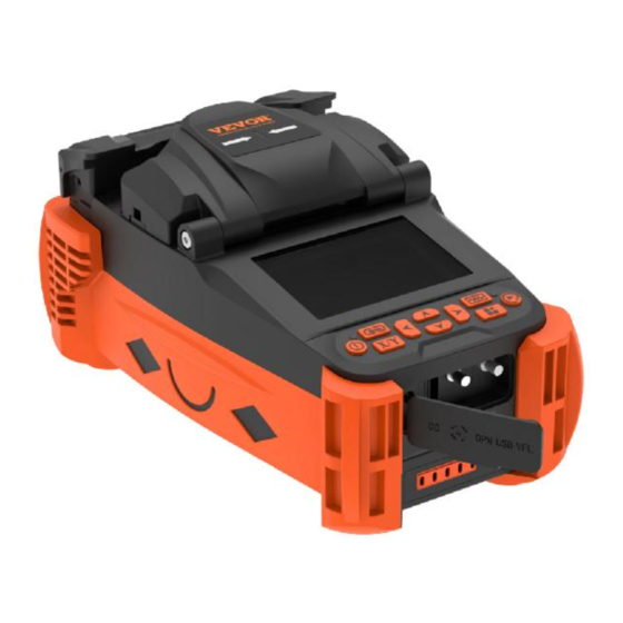
1.3 Introduction of Fusion Splicer Components Heater Wind Cover Screen Operation Buttons Output 5V/2A Charger 13.5V-2A USB Port Power Meter Battery remover switch Battery charging port NOTE: VFL and optical power meter are optional functions. -
Page 12: Operation Buttons
1.4 Operation buttons Picture Name Button function details Power Device on or off Access to the menu, confirmation Menu key under the menu Start of alignment, start of Start discharge fusion, etc. Menu cursor up, work screen shortcuts Menu cursor down, work screen Down shortcuts Menu cursor left, work screen... - Page 13 1.4.1 Splicing Electrode Cap Camera Electrode V-groove Fiber Holder LED Light Fiber Presser Red Light 1.4.2 Heater 镜头 Heater Oven SC Switch Heater Button...
-
Page 14: Chapter 2 Basic Operation
Chapter 2 Basic operation This chapter describes the basic operation of the fusion splicer. Read this chapter in detail to use the equipment correctly and to avoid problems such as damage to the equipment and no normal results. 2.1 Power supply connection The product supports the following two types of power supply: internal lithium battery pack (no external power adapter plugged in);... -
Page 15: Power On And Off
2.2 Power on and off Short press the power button " " to turn on the machine, the power button indicator turns red, the buzzer emits "beep, beep" two sounds, after which the display shows the working screen. Long press the power button to switch off the machine, you can observe that the display first turns off, the power indicator flashes, and the indicator goes out after... - Page 16 Menu Menu Description Splice Mode Set parameters in splice mode Heat Mode Set parameters in heat mode Setting parameters for discharge Function compensation, tension test, automatic settings heating of closed lids, etc. Set display parameters, menu language, System time, restore factory settings, power settings saving, etc.
- Page 17 2.3.2 Introduction to shortcut keys Four shortcut keys have been added to the workbench interface to operate the operation as follows. 1) Press and hold the " " up key for 2s, the red light on logo will appear on the right side of the workbench, at this time, it means the red light is on.
-
Page 18: Preparation Before Splicing
table will jump to the ARC calibration screen. 4)Press and hold the " " right button for 2s and the workbench will jump to the red light setting screen. 2.4 Preparation before splicing... - Page 19 2.4.1 Stripping of protective layers other than the fiber coating Strip drop cable Peel off the outer plastic layer with the large jaw of the Strip pigtail Cut away the Kevlar with scissors patch cord Peel off the inner plastic layer with small jaws using 3-hole stripper.
- Page 20 2.4.3 Removal and cleaning of fiber optic coatings Stripping of fiber coating Clean fiber After stripping the fiber, a dust-free paper moistened with high purity alcohol is used to remove debris from the coating layer, starting at the interface between the coating and the bare fibre and rotating in a circular direction towards the bare fibre.
-
Page 21: System And Function Settings
2.4.5 Put fiber (1) Open the wind cover and observe if the V-slot is clean, if not, clean the V-slot as described in chapter 3, section 3.5. (2) Place the cut optical fiber into the fiber holder. (3) Observe that the end face of the fiber is positioned between the tip of the electrode and the placed in the V-slot. - Page 22 System Settings Interface System Description Provides instructions for operating the Help Information keyboard, information Brightness Adjusting the brightness of the display adjustment Language Default is the language selected at the selection time of order placement Screen flip Display rotated 180° Time setup Setting the system time clock Restore factory...
- Page 23 Function setting interface...
- Page 24 Function Description When tension test on, waiting time for Reset waiting the motor to reset after opening the time wind cover In the on condition, the tension test is Tension test performed automatically after the fusion is completed When on, automatic fusion when the Auto starting wind cover is closed When on, no fiber is detected and the...
-
Page 25: Splicing Operations
2.6 Splicing operations 2.6.1 Select the splicing program and set the splicing parameters (1)Splice mode description... - Page 26 Splice Mode Description SM, MM, DS, NZDS and other options allow the user to select the appropriate Fiber type fiber type and fusion procedure depending on the type of fiber. Splice operate Automatic, semi-automatic and manual mode options available Different fusion parameter No. can be Splice program selected according to the current fiber type, which can be selected and modified...
- Page 27 (2)Under the [ splice mode] menu select [ Edit splice program]. Edit splice Description program Set the pre-discharge time from the Pre-Splice time start of discharge to the propulsion of the fiber Set the pre-discharge intensity from the Pre-Arc current start of the discharge to the propulsion of the fiber Arc time...
- Page 28 2.6.2 Splicing loss estimation and quality evaluation After the splicing of the fibers has been completed, the evaluation of the splicing loss is shown on the right side of the display. The limit value for the splicing loss is set in the menu [Fusion Splice Settings].
-
Page 29: Splice Result Save And Find
Low fusion current time】 or short discharge time Small splicing Do【detect system propulsion parameter】 Small splicing advance Down 【Pre-Arc Fiber High splicing current current】Or down separation / Long discharge 【Pre-Splice time】 time Down 【Overlap ... -
Page 30: Heating Operation
2.8 Heating Operation Records Description Total arc Number of electrode discharges since number last zeroing Clear arc count Zero discharge count Splicing records already stored in the Total records system Check splicing time, loss estimation, View records etc. Detect records Delete all splicing records Query fault Human error and all kinds of... - Page 31 Heating mode Description The system has pre-stored heating Heating program programs for different heat shrink sleeves, plus a number of user-set programs Casing type 10mm-60mm ordinary casing, FC/SC Casing diameter 1-8mm Heating Upper temperature limit for heating temperature process Heating time Heat shrinkage heating time Note: Select [Heating Mode] in the main menu and choose the appropriate heating program according to...
-
Page 32: Opm And Vfl Operation
heating bath, then cover the heater with the heating indicator light on. (4) After the heating action is completed, the heating indicator light goes out; at this time, you need to open the heater cover immediately and remove the optical fiber. - Page 33 Description Set the current required Wavelength measurement wavelength parameter Compensation Compensation of loss deviations (2)Select 【VFL】in the main menu to enter VFL setting menu Red light on operation: Press the“ ”key to turn on the red light and keep the constant light setting, press the“...
-
Page 34: Chapter 3 Maintenance
Chapter 3 Maintenance 3.0 Equipment maintenance menu Maintain Description Performs discharge calibration Arc correction operations and automatically corrects the discharge current Multiple high current discharges to Clean electrodes clean the electrodes Automatic determination of the discharge position and multiple Replace electrodes discharge stabilization of the electrode after replacement Automatic self-test of electrode... -
Page 35: Arc Correction
3.1 Arc Correction It is strongly recommended that the fusion splicer should be calibrated after a change in the type of fiber, a system upgrade, a large change in the temperature, humidity and air pressure of the environment, continuous fusion failures or high losses, long periods of non-use of the fusion splicer or excessive use of the electrodes, cleaning or replacement of the electrodes. -
Page 36: System Parameter Self-Test
affected. The number of discharges must be cleared after replacing the electrode. Do not touch the tip of the electrode rod when replacing. (1) Before replacing the electrode, the user must switch off the power supply. (2) Loosen the screws securing the electrode cover and remove the electrode. -
Page 37: Cleaning And Maintenance Of Fusion Splicer
(1) Clean the V-groove with a cotton swab dipped in alcohol, and clean the prepared optical fiber. (2) Select [Detect system parameters] in the [Maintain] menu, and press the menu key twice continuously to enter the system parameter self-test interface. (3) Put the cut optical fiber into the fusion splicer, close the windproof cover, and press the start button to start the system parameter self-test. - Page 38 Cleaning the fiber optic presser foot Open the windproof cover, wipe the surface of the presser foot with a fine cotton swab dipped in alcohol, make sure it is clean, and then dry the presser foot with a dry cotton swab. Clean the lens (1) Turn off the power of the fusion splicer and open the windproof cover.
-
Page 39: Chapter 4 Password Control Function (Optional)
Chapter 4 Password Control Function (Optional) 4.1 Management options interface Enter the management interface through "Management Options" under the "System Settings" interface. Functions such as the validity period of the fusion splicer, the number of valid times of use, and the power-on password can be controlled through the management options. - Page 40 1. "Validity period verification": When the validity period verification function is enabled, no matter whether the power-on mandatory password verification function is enabled or not, if the system detects that the set validity period has expired, the system will pop up the password login interface, and the key composed of red numbers will appear on the password login interface.
- Page 41 password after the input is correct. When the valid times verification function is turned off, the system no longer limits the number of uses. 4. "Valid times": the number of welding times the machine can use. 5. When "Validity Verification" and "Validity Times" are enabled at the same time, "Validity Verification"...
-
Page 42: Power-On Password Login Interface Introduction
right keys to adjust the character to be input; press the menu key to use the selected character as the current input. Press the reset key to cancel the current input password; press the start key to save the current input password and prompt that the setting is successful. -
Page 43: Appendix 1 Warning Information
the temporary power-on password. After the input is correct, the system will automatically Password before activation. The key will not appear on this interface if the validity period or the number of valid times has not been exceeded. 4. If the validity period verification function is turned on, the validity period of the fusion splicer will be displayed on this interface. - Page 44 incorrectly after sales service connected department 1.Right fiber is cleaved too short; 2.The part of right fiber put into V-groove is Right fiber broken; Solutions refer to placement is 3.Right fiber is the above incorrect(RFPC) not put into the center of V-groove 4.Right propulsion motor...
- Page 45 cleaved poorly, such as core defect, cladding defect or fiber incompleteness Left and Right Solutions refer to fiber head The same as face are above above unqualified Re-cleave left fiber. cutting quality is still poor after multiple trial , replace the blade Left fiber head Left fiber head...
- Page 46 sides in the horizontal and vertical directions are greater than the set threshold. 1、 splice loss Clean v-groove, exceeds reoperate Estimated loss limit; amount is 【Arc calibration】 2、 The selected too much program do then not match splice again the fiber type Current Use power adapter Power is too...
-
Page 47: Appendix 2 Problems And Troubleshooting
Appendix 2 Problems and Troubleshooting Abnormal Reason Countermeasures phenomena arc sounds Electrodes are Reinstall electrode abnormally incorrectly strictly placed 1.Electrodes are incorrectly 1、 Reinstall electrode arc delay or placed strictly system could 2.The 2、 Clean electrode tip not arc electrode tip is or replace electrode wrapped by monox... - Page 48 1.Fiber is dusty; 1.Re-make optical fiber, 2. The fiber splice again; type or fusion 2. Choose the right type splice program of fiber and fusion splice selected is program; Fiber splicing wrong; 3.Operate【Arc point’s quality 3. Fusion calibration】 to obtain the is poor splice environment...
- Page 49 running 2、The selected welding abnormal mode - > 】 【 splice operation mode 】 menu, enter the "manual" mode, select operation about optical fiber, the operator can be through four direction key move the corresponding side of optical fiber, motor back the center of the field, and then do system parameters...
- Page 50 Disposal information: This product is subject to the provision of European Directive 2012/19/EU. The symbol showing a wheelie bin crossed through indicates that the product requires separate refuse collection in the European Union. This applies to the product and all accessories marked with this symbol.
- Page 51 Technical Support and E-Warranty Certificate www.vevor.com/support MADE IN CHINA...
Need help?
Do you have a question about the ALK-T1 and is the answer not in the manual?
Questions and answers