
Related Manuals for HERKULES G210


Summary of Contents for HERKULES G210
- Page 1 Part# 1002733-03 3/14/2012 This manual contains important information concerning the installation and operation of the gun washers listed above. Read manual thoroughly and keep for future reference INSTRUCTIONS Page 1 of 19...
-
Page 2: Table Of Contents
Table of Contents Warnings ……………………………………………………………………………………………………………………… 3-4 Assembly Instructions ……………………………………………………………………………………………………….. 5-6 Model Information ……………………………………………………………………………………………………………. 7 Installation ………………………………………………………………………………………………………………….. 7 Operation ……………………………………………………………………………………………………………………. 8-10 Preventive Maintenance ………………………………………………………………………………………………………. 10 Troubleshooting ……………………………………………………………………………………………………………… 11 Drawings with part lists: …………………………………………………………………………………………………… 12-18 Warning Symbol Warning Symbol Caution Symbol Caution Symbol CAUTION WARNING This symbol alerts you to the possibility of serious... -
Page 3: Warnings
WARNING EQUIPMENT MISUSE HAZARD Equipment misuse can cause the equipment to rupture, malfunction, or start unexpectedly and result in serious injury. • This equipment is for professional use only. • Read all instruction manuals, tags, and labels before operating the equipment. •... - Page 4 WARNING FIRE AND EXPLOSION HAZARD Improper grounding, poor air ventilation, open flames, or sparks can cause a hazardous condition and result in fire or explosion and serious injury. • Ground the equipment. See Installation for grounding procedure. • Provide fresh air ventilation to avoid the build up of flammable fumes from the cleaning solution. •...
-
Page 5: Assembly Instructions
Assembly Stand and tub connections STEP 1 Position the pump mount bracket between the timer leg and the filter/regulator leg of the stand assembly. Attach the pump mount bracket to the stand using (2) 1/4-20 x 1/2 hex bolts, (2) #10 flat washers, (2) 1/4" lock washers and (2) 1/4"... - Page 6 Assembly Connecting fluid and air hoses STEP 6 Insert the nipple and bushing end of the 3-way valve Limit valve 20" Fluid assembly into the upper bulkhead in the tub. Use sealant tube to avoid leaking and orient as shown (see fig.4). STEP 7 Connect the 13"...
-
Page 7: Model Information
Dimensions in./(mm) lbs/(kg) Two gun, two cup paint gun washer equipped with diaphragm 20 625 20.625 25 5 25.5 21 25 21.25 G210 G210 pump, filter-regulator and timer. Adapted for pressure feed filt d ti t d f (1168) (524) (648) -
Page 8: Operation
Operation Filling the Gun Washer with Fluid Placing Equipment in the Gun Washer Close ball valve located on the bottom of the tank. To clean guns not mentioned here, use the long or short stem supports as needed (see Fig. 8). For questions or Pour five gallons (18.9 liters) of high quality adapter kits contact your paint gun washer distributor. - Page 9 Operation Operating the Gun Washer Make sure all wire trigger locks and other accessories If the lid is opened prior to the end of the timing cycle, the are inside the gun washer tub. safety air cutoff switch will stop the gun washer. The gun washer will start again when the lid is closed if time If washing only one set of equipment, place empty cans over remains on the timer.
-
Page 10: Preventive Maintenance
Operation Washing Pressure Pot and Lid Remove the 1/8" NPT hex plug from the manifold block (see fig.11). Insert the spray nozzle assembly into the manifold block (see fig.11). Place the pot over the spray nozzle assembly and place Spray nozzle the pickup tube of the lid over one of the short stem supports. -
Page 11: Troubleshooting
Troubleshooting Problem Possible Solution Gun washer will not turn on. Make sure the air line is properly connected with at least 75 psi. Air pressure is regulated at 75 psi. Make sure lid is fully closed. Make sure the lid rod actuator is making full contact with the limit valve on the right rear leg. -
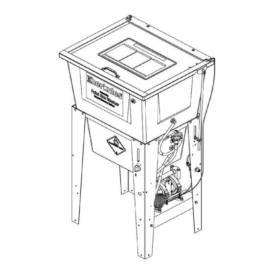
Page 12: Drawings With Part Lists
G210 Parts Layout Page 12 of 19... - Page 13 G210 Parts Layout Part # Description Quantity Ball Valve 1 EA. 11958 Pump Mounting Bracket 1 EA. 13844 Stand Assembly 1 EA. See pg. 16 12025 Lid Assembly 1 EA. See pg. 14 12734 Manifold Assembly 1 EA. See pg. 15...
- Page 14 Rivet 3/16 x 1/2 - Aluminum 4 EA. Rivet 3/16 x 1/4 - Stainless 2 EA. Hinge 2 EA. Note: Parts are shown for reference purposes only and are not necessarily part of a Herkules assembly. Page 14 of 19...
- Page 15 54P1 Full jet Nozzle - White 12 EA. 64PE Manifold Hose 7 IN. Nipple 4-1/2" - Brass 2 EA. Note: Parts are shown for reference purposes only and are not necessarily part of a Herkules assembly. Page 15 of 19...
- Page 16 G210 Pump and Legs Layout Page 16 of 19 Page 16 of 19...
- Page 17 2 EA. T17M Filter / Regulator 1 EA. 5/32 Hose fitting 90° Swivel 2 EA. Note: Parts are shown for reference purposes only and are not necessarily part of a Herkules assembly. Page 17 of 19 Page 17 of 19...
- Page 18 G210 Hardware Layout Part # Description Quantity 001-702 Bolt Hex 1/4-20 x 1/2 - Zinc 2 EA. 001-705 Washer Flat 1/4 USS - Zinc 2 EA. 002-161 Washer Flat #10 USS - Zinc 2 EA. 008-244 Acorn Nut 1/4-20 - Nickel 2 EA.
Need help?
Do you have a question about the G210 and is the answer not in the manual?
Questions and answers