Table of Contents
Advertisement
Quick Links
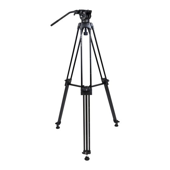
Congratulations on your purchase of this ProMaster 24P Video Tripod Kit. Please read these instructions
thoroughly to ensure proper assembly, operation, and adjustment of your new tripod kit. With proper use and
adjustments your 24P Video Tripod Kit will provide many years of excellent service.
ASSEMBLY:
Attaching the Handles
The 24P includes two Handles (5) for your convenience. You may mount one or both. Simply connect each handle
to the head of the tripod using its Handle Connection Ports (6). Each handle has a knob for making this
connection. While installing each handle you can also choose the best angle for a comfortable grip.
Understanding the Bowl System and Flat Base
A 75mm half-ball comes preattached to the flat base (bottom) of the head and works with a bowl that is
integrated into the yoke of the tripod for leveling the head. It is highly recommended you check the connection
between the half-ball and the base of the head before use to be sure it is tight. To do this begin by loosening and
removing the Bowl Handle (17) followed by lifting the head and half-ball out of the top of the tripod (do all of this
without a camera attached). Turn the head upside down so you are looking at the bottom of the half-ball. Notice
the 3 Grub Screws (16). Check all 3 of these screws to ensure they are tight using a 3mm hex wrench. If the
screws are not tight you can reinstall the half-ball by loosening all 3 screws, taking hold of the half-ball, turning it
clockwise until it is tight against the flat base of the head, and then tightening all 3 Grub Screws (16). Replace the
head and half-ball into the top yoke of the tripod and reattach the Bowl Handle (17).
The 24P uses a flat base for its head with a common
/
"-16 threaded port in the center of that base. This flat base
3
8
allows you to mount the head on other tripods, sliders, and apparatus for a variety of video techniques. When
you need to mount the head to another apparatus remove it from the tripod by loosening and removing the Bowl
Handle (17). Then turning the head over and loosening all 3 Grub Screws (16). Finally, remove the half-ball from
the head by turning it counterclockwise. Do these steps in reverse order to reinstall the head onto the tripod.
Mounting the Quick Release Plate to Your Camera
Locate the Quick Release Plate (1). The plate has two camera attachment screws, a ¼"-20 screw and a
/
"-16
3
8
screw. You can use one, or both, of the screws to mount your camera (or lens), depending on what type and size
of mounting ports are available on your gear. If you have the ability to use both screws it is recommended to do
so for the most secure connection. A flat-head screwdriver is best for tightening these screws. You may remove
either screw by first taking the soft plug out of the plate, then sliding the screw out, and reinstalling the plug.
Note: The plate does not have a front or back. It can be mounted either direction and will function fine with the
tripod.
An anti-twist pin is also found in the Quick Release Plate (1). This pin works with a small hole found in the base
of some video cameras. If your gear does not have this hole and you mount the QR plate, the pin will simply move
out of the way thanks to its spring-type back. The anti-twist pin can also be removed from the plate with a
phillips screwdriver.
Advertisement
Table of Contents

Related Manuals for Promaster Video Tripod 24P


Summary of Contents for Promaster Video Tripod 24P
- Page 1 Congratulations on your purchase of this ProMaster 24P Video Tripod Kit. Please read these instructions thoroughly to ensure proper assembly, operation, and adjustment of your new tripod kit. With proper use and adjustments your 24P Video Tripod Kit will provide many years of excellent service. ASSEMBLY: Attaching the Handles The 24P includes two Handles (5) for your convenience. You may mount one or both. Simply connect each handle to the head of the tripod using its Handle Connection Ports (6). Each handle has a knob for making this connection. While installing each handle you can also choose the best angle for a comfortable grip. Understanding the Bowl System and Flat Base A 75mm half-ball comes preattached to the flat base (bottom) of the head and works with a bowl that is integrated into the yoke of the tripod for leveling the head. It is highly recommended you check the connection between the half-ball and the base of the head before use to be sure it is tight. To do this begin by loosening and removing the Bowl Handle (17) followed by lifting the head and half-ball out of the top of the tripod (do all of this without a camera attached). Turn the head upside down so you are looking at the bottom of the half-ball. Notice the 3 Grub Screws (16). Check all 3 of these screws to ensure they are tight using a 3mm hex wrench. If the screws are not tight you can reinstall the half-ball by loosening all 3 screws, taking hold of the half-ball, turning it clockwise until it is tight against the flat base of the head, and then tightening all 3 Grub Screws (16). Replace the head and half-ball into the top yoke of the tripod and reattach the Bowl Handle (17). The 24P uses a flat base for its head with a common ”-16 threaded port in the center of that base. This flat base allows you to mount the head on other tripods, sliders, and apparatus for a variety of video techniques. When you need to mount the head to another apparatus remove it from the tripod by loosening and removing the Bowl Handle (17). Then turning the head over and loosening all 3 Grub Screws (16). Finally, remove the half-ball from the head by turning it counterclockwise. Do these steps in reverse order to reinstall the head onto the tripod. Mounting the Quick Release Plate to Your Camera Locate the Quick Release Plate (1). The plate has two camera attachment screws, a ¼”-20 screw and a ”-16 screw. You can use one, or both, of the screws to mount your camera (or lens), depending on what type and size of mounting ports are available on your gear. If you have the ability to use both screws it is recommended to do so for the most secure connection. A flat-head screwdriver is best for tightening these screws. You may remove either screw by first taking the soft plug out of the plate, then sliding the screw out, and reinstalling the plug. Note: The plate does not have a front or back. It can be mounted either direction and will function fine with the tripod. An anti-twist pin is also found in the Quick Release Plate (1). This pin works with a small hole found in the base of some video cameras. If your gear does not have this hole and you mount the QR plate, the pin will simply move out of the way thanks to its spring-type back. The anti-twist pin can also be removed from the plate with a phillips screwdriver.
- Page 2 Mounting your Camera Once the Quick Release Plate (1) is securely fastened to your camera or lens you are ready to mount it to the tripod. Loosen the Quick Release Knob (3) and slide the plate onto the head from the back, using a forward motion. To ease this task, you may hold-in the Quick Release Button (4), but this is not necessary for mounting. Once you are sure a solid connection has been made, tighten the Quick Release Knob (3) before releasing the camera. This quick release system is designed to slide and be repositionable along the length of the plate so you can find the best balance point for your gear. When properly balanced the tripod head will operate at its best and your gear will be safest (an out-of-balance rig can tip over) Note: When the Quick Release Button (4) is released (not pushed in) a safety catch should prevent the camera from accidentally sliding out of the head when the Quick Release Knob (3) is loosened. However, you should always keep a strong hold on your camera and lens for extra security to prevent it from falling when the Quick Release Knob (3) is loosened. To remove your camera, hold on to it securely, loosen the Quick Release Knob (3) and then press and hold-in the Quick Release Button (4) while you slide the camera out of the head. OPERATION: Adjusting and Extending the Legs Use the Leg Locks (12) to adjust the length of each leg. Turn each Leg Lock (12) counterclockwise to loosen it or clockwise to tighten it. When a lock is loose, you can freely move the leg by extending or retracting it. For times when the tripod is not set to its maximum height, extend the middle sections before the lower sections. Using the middle sections first will increase stability. Each leg has Height Lines (14) etched into the tubes. These are a visual guide to help you adjust each leg to the same height when that is the goal. Note: Be sure not to overtighten any of the Leg Locks (12). They have hard stopping points. If you force one of the locks beyond its stopping point the mechanism may break. You can adjust the angle of each leg by use of the Spreader (10). Notice the 3 Spreader Locks (11). Each lock can be independently loosened to change the angle of the attached leg and then tightened to hold that angle. This is a great way to help level your tripod on uneven terrain. When maximum stability is needed, adjust every leg to its widest angle. This ultra-wide stance will reduce the maximum possible height of the tripod, yet it will achieve the best possible overall stability. Leveling with the Bowl System Loosen the Bowl Handle (17) slightly. Grasp the head and move it around on the bowl adapter to find a level position. Watch the Bubble Level (15) as a guide. Once you have found the level point, hold the head in place while tightening the Bowl Handle (17). By leveling the head before taking video footage you will ensure the panning movements are level rather than having a tilted appearance. Operating the Head Loosen the Panning Lock (9) to allow a rotational movement of the head and camera. Or, tighten this knob to lock the head into specific position (so far as its rotation is concerned). The 24P head uses static drag for the panning movement. This means there is a set amount of resistance when panning the head. It is designed to create smooth, fluid-like movements. The Panning Lock (9) is only to lock or unlock the movement. It cannot be used to change the amount of drag. Two knobs are used for the tilting movement of the head. The Tilt Lock (7) works similar to the Panning Lock by either unlocking this motion or locking it into a fixed position. The Tilt Drag (8) allows you to set the amount of resistance to the tilting movement of the head when the Tilt Lock (7) is unlocked. Turn the Tilt Drag (8) knob clockwise to apply more resistance and counterclockwise to apply less. Even with the tilt drag set to its minimum...
- Page 3 Note: It is important for the camera to be properly balanced on the head (using the QR plate’s sliding design) for the tilt to work correctly. If the camera rig is out of balance the tilt will not provide smooth movements. Using the Accessory Ports Two Accessory Ports (2) are located on the tripod head. One port is a ”-16 thread and the other, smaller port, is a ¼”-20 thread size. Use these to connect accessories such as flex arms, and spigots, lights and mics, etc. Using the Retractable Feet At the bottom of each leg, you will find a soft foot connected with a ball joint. This joint allows the foot to sit flat against the floor regardless of the leg-angle setting, thereby providing the best stability. When using the tripod outdoors in conditions where a metal spike is preferred, grab ahold of each foot (one at a time) and spin it clockwise. As the foot is spun it will retract towards the tripod exposing a metal spike. In this position the ball- joint will no longer allow the foot to change positions as the spike takes over. Spin each foot counterclockwise to return to the original position. PRECAUTIONS: 1) Ensure all Leg Locks (12) are tightened before mounting a camera. 2) Check that the Spreader Locks (11) are tightened before mounting a camera. 3) Lock the Panning Lock (9) and Tilt Lock (7) before mounting a camera. 4) Make sure the bowl system is leveled and locked in place before mounting a camera. 5) Always hold onto the camera when loosening the Quick Release Knob (3) for mounting or dismounting the camera. 6) Do not exceed the maximum load capacity of this tripod kit This includes the weight of any accessories mounted to your camera and to the Accessory Ports (2). 7) Always be sure the Quick Release Plate (1) is securely attached to your camera or lens before each use. 8) This tripod kit is not waterproof. Do no submerge it or expose it to wet conditions. 9) Be sure the spikes are retracted before setting the tripod onto any type of floor or surface that is soft and could be easily damaged. 10) Use weight bags on the legs for added stability whenever possible. 11) Be sure the Grub Screws (16) are tight and the half-ball is fastened securely to the head before use. 12) This tripod is designed for use with specific ProMaster Quick Release plates. Only use plates designated for use with this product. ONE YEAR UNCONDITIONAL WARRANTY If for any reason, this ProMaster product fails within ONE YEAR of the date of purchase, return this product to your ProMaster dealer and it will be exchanged for you at no charge. ProMaster products are guaranteed for ONE FULL YEAR against defects in workmanship and materials. If at any time after one year, your ProMaster product fails under normal use, we invite you to return it to ProMaster for evaluation. Made in China WWW.PROMASTER.COM | FAIRFIELD, CT 06825...
Need help?
Do you have a question about the Video Tripod 24P and is the answer not in the manual?
Questions and answers