Table of Contents
Advertisement
Quick Links
PT880 PRO-A7
FCC Information and Copyright
This equipment has been tested and found to comply with the limits of a Class
B digital device, pursuant to Part 15 of the FCC Rules. These limits are designed
to provide reasonable protection against harmful interference in a residential
installation. This equipment generates, uses and can radiate radio frequency
energy and, if not installed and used in accordance with the instructions, may
cause harmful interference to radio communications. There is no guarantee
that interference will not occur in a particular installation.
The vendor makes no representations or warranties with respect to the
contents here and specially disclaims any implied warranties of merchantability
or fitness for any purpose. Further the vendor reserves the right to revise this
publication and to make changes to the contents here without obligation to
notify any party beforehand.
Duplication of this publication, in part or in whole, is not allowed without first
obtaining the vendor's approval in writing.
The content of this user's manual is subject to be changed without notice and
we will not be responsible for any mistakes found in this user's manual. All the
brand and product names are trademarks of their respective companies.
i
Advertisement
Chapters
Table of Contents

Subscribe to Our Youtube Channel
Related Manuals for Biostar PT880 PRO-A7


Summary of Contents for Biostar PT880 PRO-A7
- Page 1 PT880 PRO-A7 FCC Information and Copyright This equipment has been tested and found to comply with the limits of a Class B digital device, pursuant to Part 15 of the FCC Rules. These limits are designed to provide reasonable protection against harmful interference in a residential installation.
-
Page 2: Table Of Contents
Table of Contents Chapter 1: Introduction .............. 1 Motherboard Features ..............1 Package List..................4 Layout and Components..............5 Chapter 2: Hardware Installation ..........6 Installing Central Processing Unit (CPU) ........6 FAN Headers ..................8 Installing System Memory .............. 9 Connectors and Slots .............. -
Page 3: Chapter 1: Introduction
PT880 PRO-A7 CHAPTER 1: INTRODUCTION OTHERBOARD EATURES A. Hardware Supports Socket 775. Supports Intel Pentium 4 processor up to 3.8GHz. Front side bus at the following frequency ranges: 533MT/s (133MHz Core Clock) 800MT/s (200MHze Core Clock) Supports Hyper-Threading Technology. Chipset North Bridge: VIA PT880 Pro. - Page 4 PT880 PRO-A7 10/100 LAN Chip: VT6103L. Half and Full Duplex. 10/100Mbps auto negotiation. Onboard Serial ATA Integrated in VT8237R. Supports RAID 0 and RAID 1 functions. Supports 2 serial ATA (SATA) ports. Data transfer rates up to 150 MB/s. Compliant with SATA Version 1.0 specification.
- Page 5 PT880 PRO-A7 Internal On-board I/O Connectors and Headers 1 front panel header supports front panel facilities. 1 CD-in connector supports 1 CD-ROM audio-in device. 1 front audio header supports front panel audio function. 1 S/PDIF-Out connector supports digital audio-out function.
-
Page 6: Package List
PT880 PRO-A7 B. BIOS & Software BIOS Award legal BIOS. Supports APM1.2. Supports ACPI. Supports USB Function. Software Supports 9 Touch , Flasher , WinFlasher , and Warpspeeder ACKAGE FDD cable x 1 HDD cable x 1 User’s Manual x 1... -
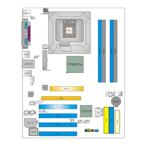
Page 7: Layout And Components
PT880 PRO-A7 AYOUT AND OMPONENTS JKBMS1 JAUXPWR1 JKBV1 LGA775 CPU1 JCFAN1 (optional) JUSB1 JUSBV2 PT880 Pro JUSBLAN1 JATXPWR1 JAUDIO1 AGP1 Codec JSPDIF_IN1 BAT1 (optional) PCI1 JSATA2 JCDIN1 VT8237R JDJ1(optional) JSPDIF_OUT1 PCI2 JSATA1 JUSBV3 JUSB3 JUSB4 JCI1 Super I/O PCI3 JPANEL1... -
Page 8: Chapter 2: Hardware Installation
PT880 PRO-A7 CHAPTER 2: HARDWARE INSTALLATION (CPU) NSTALLING ENTRAL ROCESSING Special Notice: Remove Pin Cap before installation, and make good preservation for future use. When the CPU is removed, cover the Pin Cap on the empty socket to ensure pin legs won’t be damaged. - Page 9 PT880 PRO-A7 Step 2: Look for the black cut edge on socket, and the white dot on CPU should point wards this black cut edge. The CPU will fit only in the correct orientation. Step 2-1: Step 2-2: Step 3: Hold the CPU down firmly, and then close the lever to complete the installation.
-
Page 10: Fan Headers
PT880 PRO-A7 FAN H EADERS These fan headers support cooling-fans built in the computer. The fan cable and connector may be different according to the fan manufacturer. Connect the fan cable to the connector while matching the black wire to pin#1. -
Page 11: Installing System Memory
PT880 PRO-A7 NSTALLING YSTEM EMORY 1. Unlock a DIMM slot by pressing the retaining clips outward. Align a DIMM on the slot such that the notch on the DIMM matches the break on the Slot. 2. Insert the DIMM vertically and firmly into the slot until the retaining chip... -
Page 12: Connectors And Slots
PT880 PRO-A7 ONNECTORS AND LOTS FDD1: Floppy Disk Connector The motherboard provides a standard floppy disk connector that supports 360K, 720K, 1.2M, 1.44M and 2.88M floppy disk types. This connector supports the provided floppy drive ribbon cables. IDE1/IDE2: Hard Disk Connectors... - Page 13 PT880 PRO-A7 PCI1~PCI4: Peripheral Component Interconnect Slots This motherboard is equipped with 4 standard PCI slots. PCI stands for Peripheral Component Interconnect, and it is a bus standard for expansion cards. This PCI slot is designated as 32 bits. PCI1...
- Page 14 PT880 PRO-A7 AGP1: Accelerated Graphics Port Slot Your monitor will attach directly to that video card. This motherboard supports video cards for PCI slots, but it is also equipped with an Accelerated Graphics Port (AGP). An AGP card will take advantage of AGP technology for improved video efficiency and performance, especially with 3D graphics.
-
Page 15: Chapter 3: Headers & Jumpers Setup
PT880 PRO-A7 CHAPTER 3: HEADERS & JUMPERS SETUP OW TO ETUP UMPERS The illustration shows how to set up jumpers. When the jumper cap is placed on pins, the jumper is “close”, if not, that means the jumper is “open”. - Page 16 PT880 PRO-A7 JKBV1: Power Source Header for PS/2 Keyboard and Mouse Pin 1-2 Close +5V for PS/2 keyboard and mouse. Pin 2-3 close PS/2 keyboard and mouse are powered by +5V standby voltage. Note: In order to support this function “Power-on system via keyboard and mouse”, “JKBV1”...
- Page 17 PT880 PRO-A7 JAUXPWR1: Power Source Connector for CPU Power Circuit By connecting this connector, it will provide +12V to CPU power circuit. Assignment +12V +12V Ground Ground JUSB3/JUSB4: Headers for USB 2.0 Ports at Front Panel This header allows user to connect additional USB cable on the PC front panel, and also can be connected with internal USB devices, like USB card reader.
- Page 18 PT880 PRO-A7 JPANEL1: Header for Front Panel Facilities This 24-pin connector includes Power-on, Reset, HDD LED, Power LED, Sleep button, speaker and IrDA Connection. It allows user to connect the PC case’s front panel switch functions. PWR_LED On/Off HLED Assignment...
- Page 19 PT880 PRO-A7 JAUDIO2: Front Panel Audio Header This header allows user to connect the front audio output cable with the PC front panel. It will disable the output on back panel audio connectors. Assignment Mic in/center Ground Mic power/Bass Audio power...
- Page 20 PT880 PRO-A7 JCMOS1: Clear CMOS Header By placing the jumper on pin2-3, it allows user to restore the BIOS safe setting and the CMOS data, please carefully follow the procedures to avoid damaging the motherboard. Pin 1-2 Close: Normal Operation (default).
- Page 21 PT880 PRO-A7 J WOL1 (optional): Wake on LAN Header The connector powers up the system when a wakeup packet or signal is received from the network. This feature requires the Wake up on LAN function in BIOS is set to Enabled and that your system has an ATX power supply with at least 720mA +5V standby power.
-
Page 22: Chapter 4: Useful Help
BIOS contents are corrupted. In this Case, please follow the procedure below to restore the BIOS: 1. Make a bootable floppy disk. 2. Download the Flash Utility “AWDFLASH.exe” from the Biostar website: www.biostar.com.tw 3. Confirm motherboard model and download the respectively BIOS from Biostar website. - Page 23 PT880 PRO-A7 B. CPU Overheated If the system shutdown automatically after power on system for seconds, that means the CPU protection function has been activated. When the CPU is over heated, the motherboard will shutdown automatically to avoid a damage of the CPU, and the system may not power on again.
-
Page 24: Troubleshooting
PT880 PRO-A7 ROUBLESHOOTING Probable Solution No power to the system at all Make sure power cable is Power light don’t illuminate, fan securely plugged in. inside power supply does not turn Replace cable. Contact technical support. Indicator light on keyboard does not turn on. -
Page 25: Warpspeeder
PT880 PRO-A7 WARPSPEEDER™ CHAPTER 5: NTRODUCTION [WarpSpeeder™], a new powerful control utility, features three user-friendly functions including Overclock Manager, Overvoltage Manager, and Hardware Monitor. With the Overclock Manager, users can easily adjust the frequency they prefer or they can get the best CPU performance with just one click. The Overvoltage Manager, on the other hand, helps to power up CPU core voltage and Memory voltage. -
Page 26: Installation
PT880 PRO-A7 NSTALLATION 1. Execute the setup execution file, and then the following dialog will pop up. Please click “Next” button and follow the default procedure to install. 2. When you see the following dialog in setup procedure, it means setup is completed. -
Page 27: Warpspeeder™] Includes 1 Tray Icon And 5 Panels
PT880 PRO-A7 ™] PEEDER INCLUDES TRAY ICON AND PANELS 1. Tray Icon: Whenever the Tray Icon utility is launched, it will display a little tray icon on the right side of Windows Taskbar. This utility is responsible for conveniently invoking [WarpSpeeder™] Utility. - Page 28 PT880 PRO-A7 2. Main Panel If you click the tray icon, [WarpSpeeder™] utility will be invoked. Please refer to the following figure; the utility’s first window you will see is Main Panel. Main Panel contains features as follows: a. Display the CPU Speed, CPU external clock, Memory clock, AGP clock, and PCI clock information.
- Page 29 PT880 PRO-A7 3. Voltage Panel Click the Voltage button in Main Panel, the button will be highlighted and the Voltage Panel will slide out to up as the following figure. In this panel, you can decide to increase CPU core voltage and Memory voltage or not.
- Page 30 PT880 PRO-A7 4. Overclock Panel Click the Overclock button in Main Panel, the button will be highlighted and the Overclock Panel will slide out to left as the following figure. Overclock Panel contains the these features: a. “–3MHz button”, “-1MHz button”, “+1MHz button”, and “+3MHz button”: provide user the ability to do real-time overclock adjustment.
- Page 31 PT880 PRO-A7 “Auto-overclock button”: User can click this button and [WarpSpeeder™] will set the best and stable performance and frequency automatically. [WarpSpeeder™] utility will execute a series of testing until system fail. Then system will do fail-safe reboot by using Watchdog function. After reboot, the [WarpSpeeder™] utility will restore to the hardware default...
- Page 32 PT880 PRO-A7 6. About Panel Click the “about” button in Main Panel, the button will be highlighted and the About Panel will slide out to up as the following figure. In this panel, you can get model name and detail information in hints of all the chipset that are related to overclocking.
- Page 33 PT880 PRO-A7 Note: Because the overclock, overvoltage, and hardware monitor features are controlled by several separate chipset, [WarpSpeeder™] divide these features to separate panels. If one chipset is not on board, the correlative button in Main panel will be disabled, but will not interfere other panels’...
- Page 34 PT880 PRO-A7 BIOS Setup BIOS Setup..................1 1 Main Menu..................... 3 2 Standard CMOS Features ................6 3 Advanced BIOS Features................9 4 Advanced Chipset Features................14 5 Integrated Peripherals .................. 21 6 Power Management Setup ................27 7 PnP/PCI Configurations ................33 8 PC Health Status ..................
-
Page 35: Bios Setup
PT880 PRO-A7 BIOS Setup BIOS Setup Introduction This manual discussed Award™ Setup program built into the ROM BIOS. The Setup program allows users to modify the basic system configuration. This special information is then stored in battery-backed RAM so that it retains the Setup information when the power is turned off. - Page 36 PT880 PRO-A7 BIOS Setup PCI Bus Support This AWARD BIOS also supports Version 2.1 of the Intel PCI (Peripheral Component Interconnect) local bus specification. DRAM Support DDR SDRAM (Double Data Rate Synchronous DRAM) are supported. Supported CPUs This AWARD BIOS supports the Intel CPU.
-
Page 37: Main Menu
PT880 PRO-A7 BIOS Setup 1 Main Menu Once you enter Award BIOS™ CMOS Setup Utility, the Main Menu will appear on the screen. The Main Menu allows you to select from several setup functions. Use the arrow keys to select among the items and press <Enter> to accept and enter the sub-menu. - Page 38 PT880 PRO-A7 BIOS Setup Integrated Peripherals This submenu allows you to configure certain IDE hard drive options and Programmed Input/ Output features. Power Management Setup This submenu allows you to configure the power management features. PnP/PCI Configurations This submenu allows you to configure certain “Plug and Play” and PCI options.
- Page 39 PT880 PRO-A7 BIOS Setup Set User Password If the Supervisor Password is not set, then the User Password will function in the same way as the Supervisor Password. If the Supervisor Password is set and the User Password is set, the “User” will only be able to view configurations but will not be able to change them.
-
Page 40: Standard Cmos Features
PT880 PRO-A7 BIOS Setup 2 Standard CMOS Features The items in Standard CMOS Setup Menu are divided into 10 categories. Each category includes no, one or more than one setup items. Use the arrow keys to highlight the item and then use the<PgUp>... - Page 41 PT880 PRO-A7 BIOS Setup Main Menu Selections This table shows the selections that you can make on the Main Menu. Item Options Description Date mm : dd : yy Set the system date. Note that the ‘Day’ automatically changes when you set the date.
- Page 42 PT880 PRO-A7 BIOS Setup Item Options Description Halt On All Errors Select the situation in which No Errors you want the BIOS to stop All, but Keyboard the POST process and All, but Diskette notify you. All, but Disk/ Key...
-
Page 43: Advanced Bios Features
PT880 PRO-A7 BIOS Setup 3 Advanced BIOS Features Figure 3. Advanced BIOS Setup... - Page 44 PT880 PRO-A7 BIOS Setup CPU FEATURE Delay Prior to Thermal Set this item to enable the CPU Thermal function to engage after the specified time. The Choices: 4, 8, 16Min (default), 32. Thermal Management Allow you to choose the thermal management method of your monitor.
- Page 45 PT880 PRO-A7 BIOS Setup C1E Function This item Allow you to choose the C1E function. The Choices: Auto (default). Execute Disable Bit When disabled, forces the XD feature flag to always return 0. The Choices: Disabled, Enabled (default). Virtualization Technology When enabled, a VMM can utilize the additional hardware Capabilities provided by vanderpool Technology.
- Page 46 PT880 PRO-A7 BIOS Setup CPU L2 Cache ECC Checking This item allows you to enable/disable CPU L2 Cache ECC Checking. The Choices: Enabled (default), Disabled. Quick Power On Self Test Enabling this option will cause an abridged version of the Power On Self-Test (POST) to execute after you power up the computer.
- Page 47 PT880 PRO-A7 BIOS Setup Typematic Delay (Msec) Sets the delay time after the key is held down before it begins to repeat the keystroke. The Choices: 250 (default), 500, 750, 1000. Security Option This option will enable only individuals with passwords to bring the system online and/or to use the CMOS Setup Utility.
-
Page 48: Advanced Chipset Features
PT880 PRO-A7 BIOS Setup 4 Advanced Chipset Features This submenu allows you to configure the specific features of the chipset installed on your system. This chipset manage bus speeds and access to system memory resources, such as DRAM. It also coordinates communications with the PCI bus. The default settings that came with your system have been optimized and therefore should not be changed unless you are suspicious that the settings have been changed incorrectly. - Page 49 PT880 PRO-A7 BIOS Setup DRAM Clock/Drive Control Figure 4. 1 DRAM Clock/Drive Control To control the Clock/Drive. If you highlight the literal “Press Enter” next to the “DRAM Clock/Drive Control” label and then press the enter key, it will take you a submenu with...
- Page 50 PT880 PRO-A7 BIOS Setup Precharge to Active (Trp) This items allows you to specify the delay from precharge command to activate command. The Choices: 2T, 3T, 4T (default), 5T. Active to Precharge (Tras) This item allows you to specify the minimum bank active time.
- Page 51 PT880 PRO-A7 BIOS Setup AGP & P2P Bridge Control Figure 4. 2 AGP & P2P Bridge Control If you highlight the literal “Press Enter” next to the “AGP & P2P Bridge Control” label and then press the enter key, it will take you a submenu with the following options: AGP Aperture Size Select the size of the Accelerated Graphics Port (AGP) aperture.
- Page 52 PT880 PRO-A7 BIOS Setup AGP Fast Write This item allows you to select the AGP Fast Write function. The Choices: Disabled (default), Enabled. AGP Master 1 WS Write When Enabled, writes to the AGP (Accelerated Graphics Port) are executed with one-wait states.
- Page 53 PT880 PRO-A7 BIOS Setup CPU & PCI Bus Control Figure 4. 2 CPU & PCI Bus Control If you highlight the literal “Press Enter” next to the “CPU & PCI Bus Control” label and then press the enter key, it will take you a submenu with the following options: PCI Master 0 WS Write When enabled, writes to the PCI bus are executed with zero-wait states.
- Page 54 PT880 PRO-A7 BIOS Setup Memory Hole When enabled, you can reserve an area of system memory for ISA adapter ROM. When this area is reserved, it cannot be cached. Refer to the user documentation of the peripheral you are installing for more information.
-
Page 55: Integrated Peripherals
PT880 PRO-A7 BIOS Setup 5 Integrated Peripherals Figure 5. Integrated Peripherals... - Page 56 PT880 PRO-A7 BIOS Setup VIA OnChip IDE Device Figure 5. 1 VIA OnChip IDE Device The chipset contains a PCI IDE interface with support for two IDE channels. Select “Enabled” to activate the first and / or second IDE interface. If you install a primary and / or secondary add-in IDE interface, select “Disabled”...
- Page 57 PT880 PRO-A7 BIOS Setup IDE Prefetch Mode The “onboard” IDE drive interfaces supports IDE prefetching for faster drive access. If the interface does not support prefetching. If you install a primary and/or secondary add-in IDE interface, set this option to “Disabled”.
- Page 58 PT880 PRO-A7 BIOS Setup VIA OnChip PCI Device Figure 5. 2 VIA OnChip PCI Device OnChip PCI Device If you highlight the literal “Press Enter” next to the “ ” label and then press the enter key, it will take you a submenu with the following options: VIA-3058 AC97 Audio This option allows you to control the onboard AC97 audio.
- Page 59 PT880 PRO-A7 BIOS Setup Onboard LAN Boot ROM Decide whether to invoke the boot ROM of the onboard LAN chip. The Choices: Disabled (default), Enabled. Onchip USB Controller Select “Enabled” if your system contains a Universal Serial Bus (USB) controller and you have USB peripherals.
- Page 60 PT880 PRO-A7 BIOS Setup Onboard FDC Controller Select Enabled if your system has a floppy disk controller (FDC) installed on the system board and you wish to use it. If install and FDC or the system has no floppy drive, select Disabled in this field.
-
Page 61: Power Management Setup
PT880 PRO-A7 BIOS Setup 6 Power Management Setup The Power Management Setup Menu allows you to configure your system to utilize energy conservation and power up/power down features. Figure 6. Power Management Setup ACPI function This item displays the status of the Advanced Configuration and Power Management (ACPI). - Page 62 PT880 PRO-A7 BIOS Setup Power Management This category allows you to select the type (or degree) of power saving and is directly related to the following modes: 1.HDD Power Down. 2.Suspend Mode. There are four options of Power Management, three of which have fixed mode settings Min.
- Page 63 PT880 PRO-A7 BIOS Setup Video Off Method This option determines the manner in which the monitor is goes blank. V/H SYNC+Blank (default) This selection will cause the system to turn off the vertical and horizontal synchronization ports and write blanks to the video buffer.
- Page 64 PT880 PRO-A7 BIOS Setup Ac Loss Auto Restart This field determines the action the system will automatically take when power is restored to a system that had lost power previously without any subsequent manual intervention. There are 3 sources that provide current to the CMOS area that retains these Power-On instructions;...
- Page 65 PT880 PRO-A7 BIOS Setup PS2KB Wakeup from S3/ S4/ S5 This item allows you to wake up from S3/ S4/ S5 with PS2 keyboard. The Choices: Disable (default), Ctrl+F1, Ctrl+F2. Ctrl+F3, Ctrl+F4, Ctrl+F5, Ctrl+F6, Ctrl+F7, Ctrl+F8, Ctrl+F9, Ctrl+F10, Ctrl+F11,Ctrl+F12, Power, Wake, Any Key.
- Page 66 PT880 PRO-A7 BIOS Setup RTC Alarm Resume When “Enabled”, you can set the date and time at which the RTC (real-time clock) alarm awakens the system from Suspend mode. The Choices: Enabled, Disabled (default). Date (of Month) You can choose which month the system will boot up. This field is only configurable when “RTC Resume”...
-
Page 67: Pnp/Pci Configurations
PT880 PRO-A7 BIOS Setup 7 PnP/PCI Configurations This section describes configuring the PCI bus system. PCI, or Personal Computer Interconnect, is a system which allows I/O devices to operate at speeds nearing the speed of the CPU itself uses when communicating with its own special components. This section covers some very technical items and it is strongly recommended that only experienced users should make any changes to the default settings. - Page 68 PT880 PRO-A7 BIOS Setup Reset Configuration Data The system BIOS supports the PnP feature which requires the system to record which resources are assigned and protects resources from conflict. Every peripheral device has a node, which is called ESCD. This node records which resources are assigned to it.
- Page 69 PT880 PRO-A7 BIOS Setup PCI / VGA Palette Snoop Choose Disabled or Enabled. Some graphic controllers which are not VGA compatible take the output from a VGA controller and map it to their display as a way to provide boot information and VGA compatibility.
-
Page 70: Pc Health Status
PT880 PRO-A7 BIOS Setup 8 PC Health Status Figure 8. PC Health Status Shutdown Temperature This item allows you to set up the CPU shutdown Temperature. This item only effective under Windows 98 ACPI mode. The Choices: Disabled (default), 60℃/140F, 65℃/149F, 70℃/158F, 75℃/167F. -
Page 71: Frequency/ Voltage Control
PT880 PRO-A7 BIOS Setup 9 Frequency/ Voltage Control Figure 9. Frequency/ Voltage Control CPU Clock Ratio The Choices: 8X (default), 9X, 10X, 11X, 12X, 13X, 14 X, 15X, 16X, 17X, 18X, 19X, 20 X, 21 X, 22 X, and 23X. - Page 72 PT880 PRO-A7 BIOS Setup CPU Clock This item allows you to select CPU Clock, and CPU over clocking. The Choices: 100MHz (default). If unfortunately, the system’s frequency that you are selected is not functioning, there are two methods of booting-up the system.
Need help?
Do you have a question about the PT880 PRO-A7 and is the answer not in the manual?
Questions and answers