Table of Contents
Advertisement
Quick Links
PT890 775 Setup Manual
FCC Information and Copyright
This equipment has been tested and found to comply with the limits of a Class
B digital device, pursuant to Part 15 of the FCC Rules. These limits are designed
to provide reasonable protection against harmful interference in a residential
installation. This equipment generates, uses and can radiate radio frequency
energy and, if not installed and used in accordance with the instructions, may
cause harmful interference to radio communications. There is no guarantee
that interference will not occur in a particular installation.
The vendor makes no representations or warranties with respect to the
contents here and specially disclaims any implied warranties of merchantability
or fitness for any purpose. Further the vendor reserves the right to revise this
publication and to make changes to the contents here without obligation to
notify any party beforehand.
Duplication of this publication, in part or in whole, is not allowed without first
obtaining the vendor's approval in writing.
The content of this user's manual is subject to be changed without notice and
we will not be responsible for any mistakes found in this user's manual. All the
brand and product names are trademarks of their respective companies.
Advertisement
Chapters
Table of Contents

Related Manuals for Biostar PT890 775


Summary of Contents for Biostar PT890 775
- Page 1 PT890 775 Setup Manual FCC Information and Copyright This equipment has been tested and found to comply with the limits of a Class B digital device, pursuant to Part 15 of the FCC Rules. These limits are designed to provide reasonable protection against harmful interference in a residential installation.
-
Page 2: Table Of Contents
Table of Contents Chapter 1: INTRODUCTION ........3 BEFORE YOU START .................3 PACKAGE CHECKLIST ..............3 MOTHERBOARD FEATURES ............4 REAR PANEL CONNECTORS ............5 Motherboard Layout ................6 Chapter 2: Hardware Installation ......7 Installing Central Processing Unit (CPU)........7 FAN Headers..................9 Installing System Memory ..............10 Connectors and Slots ...............11 Chapter 3: Headers &... -
Page 3: Chapter 1: Introduction
PT890 775 CHAPTER 1: INTRODUCTION BEFORE YOU START Thank you for choosing our product. Before you start installing the motherboard, please make sure you follow the instructions below: Prepare a dry and stable working environment with sufficient lighting. Always disconnect the computer from power outlet before operation. -
Page 4: Motherboard Features
Motherboard Manual MOTHERBOARD FEATURES SPEC LGA 775 Supports Hyper-Threading / Execute Disable Bit/ Intel Core2Duo/ Pentium 4 / Pentium Enhanced Intel SpeedStep®/ Intel Extended D / Celeron D processor up to 3.8 GHz Memory 64 technology 533 / 800 / 1066 MHz VIA PT890 CE Chipset VIA VT8237R+... -
Page 5: Rear Panel Connectors
Audio Jack Provide Audio-In/Out and microphone connection Board Size 190 mm (W) x 294 mm (L) ATX form Factor Biostar Reserves the right to add or remove Windows 2000 / XP Support support for any OS with or without notice. -
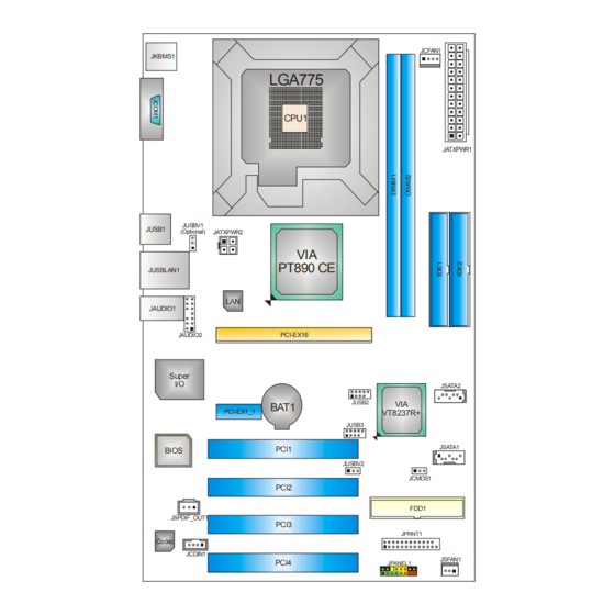
Page 6: Motherboard Layout
Motherboard Manual OTHERBOARD AYOUT JCFAN1 JKBMS1 LGA775 CPU1 JATXPWR1 JUSBV1 JUSB1 (Optional) JATXPWR2 PT890 CE JUSBLAN1 JAUDIO1 PCI-EX16 JAUDIO2 Super JSATA2 JUSB2 BAT1 PCI-EX1_1 VT8237R+ JUSB3 JSATA1 PCI1 BIOS JUSBV2 JCMOS1 PCI2 FDD1 JSPDIF_OUT1 PCI3 JPRNT1 Codec JCDIN1 JSFAN1 PCI4 JPANEL1 Note: represents the 1... -
Page 7: Chapter 2: Hardware Installation
PT890 775 CHAPTER 2: HARDWARE INSTALLATION (CPU) NSTALLING ENTRAL ROCESSING Special Notice: Remove Pin Cap before installation, and make good preservation for future use. When the CPU is removed, cover the Pin Cap on the empty socket to ensure pin legs won’t be damaged. - Page 8 Motherboard Manual Step 2: Look for the triangular cut edge on socket, and the golden dot on CPU should point forwards this triangular cut edge. The CPU will fit only in the correct orientation. Step 2-1: Step 2-2: Step 3: Hold the CPU down firmly, and then lower the lever to locked position to complete the installation.
-
Page 9: Fan Headers
PT890 775 FAN H EADERS These fan headers support cooling-fans built in the computer. The fan cable and connector may be different according to the fan manufacturer. Connect the fan cable to the connector while matching the black wire to pin#1. -
Page 10: Installing System Memory
Motherboard Manual NSTALLING YSTEM EMORY A. Memory Modules Unlock a DIMM slot by pressing the retaining clips outward. Align a DIMM on the slot such that the notch on the DIMM matches the break on the Slot. Insert the DIMM vertically and firmly into the slot until the retaining chip snap back in place and the DIMM is properly seated. -
Page 11: Connectors And Slots
PT890 775 ONNECTORS AND LOTS FDD1: Floppy Disk Connector The motherboard provides a standard floppy disk connector that supports 360K, 720K, 1.2M, 1.44M and 2.88M floppy disk types. This connector supports the provided floppy drive ribbon cables. IDE1/IDE2: Hard Disk Connectors The motherboard has a 32-bit Enhanced PCI IDE Controller that provides PIO Mode 0~4, Bus Master, and Ultra DMA 33/66/100/133 functionality. - Page 12 Motherboard Manual PCI-EX16: PCI-Express x16 Slot PCI-Express 1.0a compliant. Maximum theoretical realized bandwidth of 4GB/s simultaneously per direction, for an aggregate of 8GB/s totally. PCI-EX1_1: PCI-Express x1 slots PCI-Express 1.0a compliant. Data transfer bandwidth up to 250MB/s per direction; 500MB/s in total. PCI-Express supports a raw bit-rate of 2.5Gb/s on the data pins.
-
Page 13: Chapter 3: Headers & Jumpers Setup
PT890 775 CHAPTER 3: HEADERS & JUMPERS SETUP OW TO ETUP UMPERS The illustration shows how to set up jumpers. When the jumper cap is placed on pins, the jumper is “close”, if not, that means the jumper is “open”. - Page 14 Motherboard Manual ATX Power Source Connector: JATXPWR1 JATXPWR1 allows user to connect 24-pin power connector on the ATX power supply. Assignment Assignment +3.3V +3.3V -12V +3.3V Ground Ground PS_ON Ground Ground Ground Ground Ground PW_OK Standby Voltage+5V +12V +12V Ground +3.3V JATXPWR2: ATX Power Source Connector By connecting this connector, it will provide +12V to CPU power circuit.
- Page 15 PT890 775 JUSB2/JUSB3: Headers for USB 2.0 Ports at Front Panel This header allows user to connect additional USB cable on the PC front panel, and also can be connected with internal USB devices, like USB card reader. Assignment +5V (fused)
- Page 16 Motherboard Manual JAUDIO2: Front Panel Audio Header This header allows user to connect the front audio output cable with the PC front panel. It will disable the output on back panel audio connectors. Assignment Mic in/center Ground Mic power/Bass Audio power Right line out/ Speaker out Right Right line out/...
- Page 17 PT890 775 JCMOS1: Clear CMOS Header By placing the jumper on pin2-3, it allows user to restore the BIOS safe setting and the CMOS data, please carefully follow the procedures to avoid damaging the motherboard. Pin 1-2 Close: Normal Operation (default).
- Page 18 Motherboard Manual JSPDIF_OUT1: Digital Audio-out Connector This connector allows user to connect the PCI bracket SPDIF output header. Assignment SPDIF_OUT Ground JPRNT1: Printer Port Connector This header allows you to connector printer on the PC. Assignment Assignment -Strobe Ground -ALF Data 6 Data 0 Ground...
-
Page 19: Chapter 4: Useful Help
PT890 775 CHAPTER 4: USEFUL HELP DRIVER INSTALLATION NOTE After you installed your operating system, please insert the Fully Setup Driver CD into your optical drive and install the driver for better system performance. You will see the following window after you insert the CD The setup guide will auto detect your motherboard and operating system. -
Page 20: Award Bios Beep Code
BIOS contents are corrupted. In this Case, please follow the procedure below to restore the BIOS: 1. Make a bootable floppy disk. 2. Download the Flash Utility “AWDFLASH.exe” from the Biostar website: www.biostar.com.tw 3. Confirm motherboard model and download the respectively BIOS from Biostar website. - Page 21 PT890 775 B. CPU Overheated If the system shutdown automatically after power on system for seconds, that means the CPU protection function has been activated. When the CPU is over heated, the motherboard will shutdown automatically to avoid a damage of the CPU, and the system may not power on again.
-
Page 22: Troubleshooting
Motherboard Manual 4.4 TROUBLESHOOTING Probable Solution No power to the system at all Make sure power cable is Power light don’t illuminate, fan securely plugged in. inside power supply does not turn Replace cable. Contact technical support. Indicator light on keyboard does not turn on. -
Page 23: Chapter 5: Warpspeeder
PT890 775 WARPSPEEDER™ CHAPTER 5: NTRODUCTION [WarpSpeeder™], a new powerful control utility, features three user-friendly functions including Overclock Manager, Overvoltage Manager, and Hardware Monitor. With the Overclock Manager, users can easily adjust the frequency they prefer or they can get the best CPU performance with just one click. The Overvoltage Manager, on the other hand, helps to power up CPU core voltage and Memory voltage. -
Page 24: Installation
Motherboard Manual NSTALLATION 1. Execute the setup execution file, and then the following dialog will pop up. Please click “Next” button and follow the default procedure to install. 2. When you see the following dialog in setup procedure, it means setup is completed. -
Page 25: Warpspeeder
PT890 775 ™ PEEDER 1. Tray Icon: Whenever the Tray Icon utility is launched, it will display a little tray icon on the right side of Windows Taskbar. This utility is responsible for conveniently invoking [WarpSpeeder™] Utility. You can use the mouse by clicking the left button in order to invoke [WarpSpeeder™] directly from the little tray icon or you can... - Page 26 Motherboard Manual 2. Main Panel If you click the tray icon, [WarpSpeeder™] utility will be invoked. Please refer to the following figure; the utility’s first window you will see is Main Panel. Main Panel contains features as follows: a. Display the CPU Speed, CPU external clock, Memory clock, AGP clock, and PCI clock information.
- Page 27 PT890 775 3. Voltage Panel Click the Voltage button in Main Panel, the button will be highlighted and the Voltage Panel will slide out to up as the following figure. In this panel, you can decide to increase CPU core voltage and Memory voltage or not.
- Page 28 Motherboard Manual 4. Overclock Panel Click the Overclock button in Main Panel, the button will be highlighted and the Overclock Panel will slide out to left as the following figure. Overclock Panel contains the these features: a. “–3MHz button”, “-1MHz button”, “+1MHz button”, and “+3MHz button”: provide user the ability to do real-time overclock adjustment.
- Page 29 PT890 775 “Auto-overclock button”: User can click this button and [WarpSpeeder™] will set the best and stable performance and frequency automatically. [WarpSpeeder™] utility will execute a series of testing until system fail. Then system will do fail-safe reboot by using Watchdog function. After reboot, the [WarpSpeeder™] utility will restore to the hardware default...
- Page 30 Motherboard Manual 6. About Panel Click the “about” button in Main Panel, the button will be highlighted and the About Panel will slide out to up as the following figure. In this panel, you can get model name and detail information in hints of all the chipset that are related to overclocking.
- Page 31 PT890 775 This page is intentionally left blank...
-
Page 32: Appendencies: Spec In Other Language
Motherboard Manual APPENDENCIES: SPEC IN OTHER LANGUAGE ERMAN Spezifikationen LGA 775 Unterstützt Hyper-Threading / Execute Disable Bit Intel Core2Duo/ Pentium 4 / / Enhanced Intel SpeedStep® / Intel Pentium D / Celeron D Prozessoren Architecture-64 / Extended Memory 64 mit bis zu 3,8 GHz Technology 533 / 800 / 1066 MHz VIA PT890 CE... - Page 33 PS/2-Maus Serieller Anschluss Rückseiten- VGA-Anschluss LAN-Anschluss USB-Anschluss Audioanschluss Platinengrö 190 mm (B) X 294 mm (L) ße. Biostar behält sich das Recht vor, ohne OS-Unterst Windows 2K / XP Ankündigung die Unterstützung für ein ützung Betriebssystem hinzuzufügen oder zu entfernen.
-
Page 34: France
Motherboard Manual RANCE SPEC LGA 775 Prend en charge les technologies Processeurs Intel Core2Duo/ Pentium Hyper-Threading / d'exécution de bit de 4 / Pentium D / Celeron D jusqu'à 3,8 désactivation / Intel SpeedStep® optimisée/ d'architecture Intel 64 / de mémoire étendue 64 Bus frontal 533 / 800 / 1066 MHz VIA PT890 CE Chipset... - Page 35 Port LAN Port USB Fiche audio Dimension s de la 190 mm (l) X 294 mm (H) carte Support Biostar se réserve le droit d'ajouter ou de Windows 2K / XP supprimer le support de SE avec ou sans préavis.
-
Page 36: Italian
Motherboard Manual TALIAN SPECIFICA LGA 775 Supporto di Hyper-Threading / Execute Disable Processore Intel Core2Duo/ Pentium Bit / Enhanced Intel SpeedStep® / Architettura 4 / Pentium D / Celeron D fino a 3.8 Intel 64 / Tecnologia Extended Memory 64 533 / 800 / 1066 MHz VIA PT890 CE Chipset... - Page 37 Porta LAN Porta USB Connettore audio Dimension 190 mm (larghezza) x 294 mm i scheda (altezza) Sistemi Biostar si riserva il diritto di aggiungere o operativi Windows 2K / XP rimuovere il supporto di qualsiasi sistema supportati operativo senza preavviso.
-
Page 38: Spanish
Motherboard Manual PANISH Especificación LGA 775 Admite Hyper-Threading / Bit de deshabilitación Procesador Intel Core2Duo/ Pentium de ejecución / Intel SpeedStep® Mejorado / Intel 4 / Pentium D / Celeron D hasta 3,8 Architecture-64 / Tecnología Extended Memory 533 / 800 / 1066 MHz Conjunto VIA PT890 CE de chips... - Page 39 Conector de sonido Tamaño de 190mm. (A) X 294 Mm. (H) la placa Soporte de Biostar se reserva el derecho de añadir o retirar el sistema Windows 2K / XP soporte de cualquier SO con o sin aviso previo. operativo...
-
Page 40: Portuguese
Motherboard Manual ORTUGUESE ESPECIFICAÇÕES LGA 775 Suporta as tecnologias Hyper-Threading / Processador Intel Core2Duo/ Pentium Execute Disable Bit / Enhanced Intel SpeedStep® 4 / Pentium D / Celeron D até 3,8 GHz / Intel Arquitecture -64 / Extended Memory 64 533 / 800 / 1066 MHz VIA PT890 CE Chipset... - Page 41 Porta USB Tomada de áudio Tamanho 190 mm (L) X 294 mm (A) da placa Sistemas A Biostar reserva-se o direito de adicionar ou operativos Windows 2K / XP remover suporte para qualquer sistema operativo suportado com ou sem aviso prévio.
-
Page 42: Polish
Motherboard Manual OLISH SPEC Obsługa Hyper-Threading / Execute Disable Bit / LGA 775 Enhanced Intel SpeedStep® / Intel Procesor Procesor Intel Core2Duo/ Pentium 4 / Architecture-64 / Extended Memory 64 Pentium D / Celeron D do 3,8 GHz Technology 533 / 800 / 1066 MHz VIA PT890 CE Chipset VIA VT8237R+... - Page 43 Port szeregowy Back Panel Port VGA Port LAN Port USB Gniazdo audio Wymiary 190 mm (S) X 294 mm (W) płyty Obsluga Biostar zastrzega sobie prawo dodawania lub systemu Windows 2K / XP odwoływania obsługi dowolnego systemu operacyjn operacyjnego bez powiadomienia.
-
Page 44: Russian
Motherboard Manual RUSSIAN СПЕЦ. Поддержка технологий Hyper-Threading / (централь LGA 775 Execute Disable Bit / Enhanced Intel SpeedStep® ный Процессор Intel Core2Duo/ Pentium / Intel Architecture-64 / Extended Memory 64 процессор 4 / Pentium D / Celeron D до 3.8 ГГц Technology 533 / 800 / 1066 МГц... - Page 45 ввода-выв USB-порт ода Гнездо для подключения наушников Размер 190 мм (Ш) X 294 мм (В) панели Biostar сохраняет за собой право добавлять Поддержк Windows 2K / XP или удалять средства обеспечения для OS с а OS или без предварительного уведомления.
-
Page 46: Arabic
Motherboard Manual ARABIC اﻟﻤﻮاﺻﻔﺎت LGA 775 ﺕﺪﻋﻢ ﺕﻘﻨﻴﺎتHyper-Threading / Execute Disable Bit / ﻡﻌﺎﻟﺠﺎتIntel Core2Duo/ Pentium 4 / اﻟﻤﻌﺎﻟﺠﺔ وﺣﺪة Enhanced Intel SpeedStep® / Extended Memory Pentium D / Celeron D ﺼﻞ إﻟﻰ ﻳ ﺘﺮدد ﺑ اﻟﻤﺮآﺰﻳﺔ 64 Technology ﺝﻴﺠﺎ هﺮﺕﺰ اﻷﻡﺎﻡﻲ... - Page 47 PT890 775 اﻟﻤﻮاﺻﻔﺎت ﻋﺪد ﻓﺘﺤﺔ ﻋﺪد PCI Express ﻓﺘﺤﺔ اﻟﻔﺘﺤﺎت ﻋﺪد PCI Express x 1 ﻓﺘﺤﺔ ﻋﺪد ﻡﻨﻔﺬ ﻡﺤﺮك أﻗﺮاص ﻡﺮﻥﺔ ﻟﻤﺮﻥﺔ ا ﻟﻸﻗﺮاص ﻡﺤﺮآﻴﻦ ﻳﺪﻋﻢ ﻋﺪد ﻡﻨﻔﺬ أﺝﻬﺰة ﻡﻦ اﺙﻨﻴﻦ ﻡﻨﻔﺬ آﻞ ﻳﺪﻋﻢ ﻋﺪد ﻡﻨﻔﺬ ﻃﺎﺑﻌﺔ SATA ﻋﺪد SATA ﻡﻨﻔﺬ...
-
Page 48: Japanese
Motherboard Manual JAPANESE 仕様 Hyper-Threading / Execute Disable Bit / LGA 775 Enhanced Intel SpeedStep® / Intel Intel Core2Duo/ Pentium 4 / Pentium Architecture-64 / Extended Memory 64 D / Celeron D processor up to 3.8 GHz Technology をサポートします 533 / 800 / 1066 MHz VIA PT890 CE チップセッ... - Page 49 PT890 775 仕様 各コネクタは2つのフロッピードライブをサポートし フロッピーコネクタ ます IDEコネクタ 各コネクタは2つのIDEデバイスをサポートします プリンタポートコネクタ 各コネクタは1つのプリンタポートをサポートします SATAコネクタ 各コネクタは1つのSATAデバイスをサポートします フロントパネルコネクタ フロントパネル機能をサポートします フロントオーディオコネクタ フロントパネルオーディオ機能をサポートします CDインコネクタ CDオーディオイン機能をサポートします オンボード S/PDIFアウトコネクタ コネクタ デジタルオーディオアウト機能をサポートします CPUファンヘッダ CPUファン電源装置(スマートファン機能を搭載) システムファンヘッダ システムファン電源装置 CMOSクリアヘッダ 各コネクタは2つのフロントパネルUSBポートをサポ USBコネクタ ートします 電源コネクタ(24ピン) 電源コネクタ(4ピン) PS/2キーボード PS/2マウス シリアルポート 背面パネル VGAポート LANポート USBポート オーディオジャック...
- Page 50 PT890 775 BIOS Setup BIOS Setup ....................1 1 Main Menu ..................... 3 2 Standard CMOS Features..............7 3 Advanced BIOS Features ..............9 4 Advanced Chipset Features..............17 5 Integrated Peripherals................. 20 6 Power Management Setup ..............27 7 PnP/PCI Configurations..............33 8 PC Health Status ..................
-
Page 51: Bios Setup
PT890 775 BIOS Setup Introduction The purpose of this manual is to describe the settings in the Award™ BIOS Setup program on this motherboard. The Setup program allows users to modify the basic system configuration and save these settings to CMOS RAM. The power of CMOS RAM is supplied by a battery so that it retains the Setup information when the power is turned off. - Page 52 PT890 775 PCI Bus Support This AWARD BIOS also supports Version 2.1 of the Intel PCI (Peripheral Component Interconnect) local bus specification. DRAM Support DDR SDRAM (Double Data Rate Synchronous DRAM) is supported. Supported CPUs This AWARD BIOS supports the Intel CPU.
-
Page 53: Main Menu
PT890 775 1 Main Menu Once you enter Award BIOS™ CMOS Setup Utility, the Main Menu will appear on the screen. The Main Menu allows you to select from several setup functions. Use the arrow keys to select among the items and press <Enter> to accept and enter the sub-menu. - Page 54 PT890 775 Advanced BIOS Features This submenu allows you to configure advanced features of the BIOS. Advanced Chipset Features This submenu allows you to configure special chipset features. Integrated Peripherals This submenu allows you to configure certain IDE hard drive options and Programmed Input/ Output features.
- Page 55 PT890 775 Set Supervisor Password Setting the supervisor password will prohibit everyone except the supervisor from making changes using the CMOS Setup Utility. You will be prompted with to enter a password. Set User Password If the Supervisor Password is not set, then the User Password will function in the same way as the Supervisor Password.
- Page 56 PT890 775 Upgrade BIOS This submenu allows you to upgrade bios.
-
Page 57: Standard Cmos Features
PT890 775 2 Standard CMOS Features The items in Standard CMOS Setup Menu are divided into several categories. Each category includes no, one or more than one setup items. Use the arrow keys to highlight the item and then use the<PgUp> or <PgDn> keys to select the value you want in each item. - Page 58 PT890 775 Item Options Description Press <Enter> to enter the Options are in its sub IDE Channel 1 Master sub menu of detailed menu. options. Press <Enter> to enter the Options are in its sub IDE Channel 1 Slave sub menu of detailed menu.
-
Page 59: Advanced Bios Features
PT890 775 3 Advanced BIOS Features Figure 3: Advanced BIOS Setup Boot Seq & Floppy Setup This item allows you to setup boot sequence & Floppy. - Page 60 PT890 775 Hard Disk Boot Priority The BIOS will attempt to arrange the Hard Disk boot sequence automatically. You can change the Hard Disk booting sequence here. The Choices: Pri. Master, Pri. Slave, Sec. Master, Sec. Slave, USB HDD0, USB HDD1, USB HDD2, and Bootable Add-in Cards.
- Page 61 PT890 775 Boot Up Floppy Seek When enabled, System will test the floppy drives to determine if they have 40 or 80 tracks during boot up. Disabling this option reduces the time it takes to boot-up. The Choices: Enabled (default), Disabled.
- Page 62 PT890 775 Cache Setup CPU L1 & L2 Cache Depending on the CPU/chipset in use, you may be able to increase memory access time with this option. Enabled (default) Enable cache. Disabled Disable cache. CPU L3 Cache Depending on the CPU/chipset in use, you may be able to increase memory access time with this option.
- Page 63 PT890 775 CPU Feature Delay Prior to Thermal Set this item to enable the CPU Thermal function to engage after the specified time. The Choices: 4 Min, 8 Min, 16Min (default), 32 Min. Thermal Management This option allows you to select the way to control the “Thermal Management.”...
- Page 64 PT890 775 Limit CPUID MaxVal Set Limit CPUID MaxVal to 3, it should be “Disabled” for Windows XP. The Choices: Disabled (default), Enabled. C1E Function This item allows you to configure the Enhanced Halt State (C1E) function, which may reduce the power consumption of your system when the system is idle.
- Page 65 PT890 775 Quick Power On Self Test Enabling this option will cause an abridged version of the Power On Self-Test (POST) to execute after you power up the computer. Disabled Normal POST. Enabled (default) Enable quick POST. Boot Up NumLock Status Selects the NumLock State after the system switched on.
- Page 66 PT890 775 MPS Version Control For OS The BIOS supports version 1.1 and 1.4 of the Intel multiprocessor specification. Select version supported by the operation system running on this computer. The Choices: 1.4 (default), 1.1. OS Select For DRAM > 64MB A choice other than Non-OS2 is only used for OS2 systems with memory exceeding 64MB.
-
Page 67: Advanced Chipset Features
PT890 775 4 Advanced Chipset Features This submenu allows you to configure the specific features of the chipset installed on your system. This chipset manage bus speeds and access to system memory resources, such as DRAM. It also coordinates communications with the PCI bus. - Page 68 PT890 775 CPU & PCI Bus Control By highlighting the “Press Enter” label next to the “CPU & PCI Bus Control” and press the enter key, it will take you a submenu with the following options: Figure 4.2: CPU & PCI Bus Control PCI Master 0 WS Write When enabled, writes to the PCI bus are executed with zero-wait states.
- Page 69 PT890 775 VLink 8X Support This item allows you to enable or disable VLink 8X support. The Choices: Enabled (default), Disabled. VIA PWR Management The Choices: Enabled (default), Disabled. MEMORY HOLE You can reserve this area of system memory for ISA adapter ROM. When this area is reserved it cannot be cached.
-
Page 70: Integrated Peripherals
PT890 775 5 Integrated Peripherals Figure 5. Integrated Peripherals VIA OnChip IDE Device Highlight the “Press Enter” label next to the “VIA OnChip IDE Device” label and press enter key will take you a submenu with the following options:... - Page 71 PT890 775 OnChip SATA This option allows you to enable the on-chip Serial ATA. The Choices: Enabled (default), Disabled. SATA Mode This option allows you to select SATA Mode. The Choices: RAID, IDE (default). IDE DMA Transfer Access This item allows you to enable or disable the IDE DMA transfer access.
- Page 72 PT890 775 Primary/Secondary/Master/Slave UDMA Ultra DMA function can be implemented if it is supported by the IDE hard drives in your system. As well, your operating environment requires a DMA driver (Windows 95 or OSR2may need a third party IDE bus master driver). If your hard drive and your system software both support Ultra DMA, select Auto to enable BIOS support.
- Page 73 PT890 775 VIA OnChip PCI Device Highlight the “Press Enter” label next to the “VIA OnChip PCI Device” label and press the enter key will take you a submenu with the following options: Figure 5.2: VIA OnChip PCI Device VIA-3058 AC97 Audio This option allows you to control the onboard AC97 audio.
- Page 74 PT890 775 The Choices: All Enabled (default),1&2 USB Port, 2&3 USB Port, 1&3 USB Port, 1 USB Port, 2 USB Port, 3 USB Port, All Disabled. Onchip EHCI Controller This item allows you to enable or disable the on-chip EHCI controller.
- Page 75 PT890 775 Super IO Device Press Enter to configure the Super I/O Device. Onboard FDC Controller Select enabled if your system has a floppy disk controller (FDC) installed on the system board and you wish to use it. If you installed another FDC or the system uses no floppy drive, select disabled in this field.
- Page 76 PT890 775 default value is SPP. The Choices: SPP (default) Using Parallel port as Standard Printer Port. Using Parallel Port as Enhanced Parallel Port. Using Parallel port as Extended Capabilities Port. ECP+EPP Using Parallel port as ECP & EPP mode.
-
Page 77: Power Management Setup
PT890 775 6 Power Management Setup The Power Management Setup Menu allows you to configure your system to utilize energy conservation and power up/power down features. Figure 6. Power Management Setup ACPI Function This item displays the status of the Advanced Configuration and Power Management (ACPI). - Page 78 PT890 775 Power Management Option This category allows you to select the power saving method and is directly related to the following modes: 1. HDD Power Down. 2. Suspend Mode. There are three options of Power Management, three of which have fixed mode...
- Page 79 PT890 775 Video Off Method This option determines the manner when the monitor goes blank. V/H SYNC+Blank (default) This selection will cause the system to turn off the vertical and horizontal synchronization ports and write blanks to the video buffer.
- Page 80 PT890 775 IRQ/Event Activity Detect Figure 6.1:IRQ/Event Activity Detect Highlight the “Press Enter” label next to the “IRQ/Event Activity Detect” label and press the enter key will take you a submenu with the following options: When set to on, any event occurring at VGA Port will wake up the system.
- Page 81 PT890 775 For this function to work, you may need a LAN add-on card which supports the Wake on LAN function. Set the Wake on LAN (WOL) jumper on motherboard to enable if applicable. The Choices: Off (default), On. PowerOn by PCI Card When you select Enabled, a PME signal from PCI card returns the system to Full ON state.
- Page 82 PT890 775 IRQs Activity Monitoring Press Enter to access another sub menu used to configure the different wake up events (i.e. wake on LPT & COMM activity). Primary INTR On IRQ3 (COM2) Enabled IRQ4 (COM1) Enabled IRQ5 (LPT2) Enabled IRQ6 (Floppy Disk) Enabled...
-
Page 83: Pnp/Pci Configurations
PT890 775 7 PnP/PCI Configurations This section describes configuring the PCI bus system. PCI, or Personal Computer Interconnect, is a system which allows I/O devices to operate at speeds nearing the speed of the CPU itself uses when communicating with its own special components. - Page 84 PT890 775 Init Display First This item allows you to decide to active whether PCI Slot or on-chip VGA first. The Choices: PCEx(default), PCI Slot, AGP. Reset Configuration Data The system BIOS supports the PnP feature which requires the system to record which resources are assigned and protects resources from conflict.
- Page 85 PT890 775 IRQ Resources This submenu will allow you to assign each system interrupt a type, depending on the type of device using the interrupt. When you press the “Press Enter” tag, you will be directed to a submenu that will allow you to configure the system interrupts.
-
Page 86: Pc Health Status
PT890 775 8 PC Health Status Figure 8: PC Health Status Shutdown Temperature This item allows you to set up the CPU shutdown Temperature. This item is only effective under Windows 98 ACPI mode. The Choices: 70℃/ 158℉, 75℃/ 167℉, 80℃/ 176℉, 85℃/ 185℉(default). - Page 87 PT890 775 The Choices: 24(default). CPU Fan Full speed <℃> When CPU temperature is reach the set value, the CPU fan will work under Full Speed. The Choices: 64(default). Start PWM Value When CPU temperature arrives to the set value, the CPU fan will work under Smart Fan Function mode.
-
Page 88: Performance Booster Zone
PT890 775 9 Performance Booster Zone Figure 9: Performance Booster Zone... - Page 89 PT890 775 DRAM Clock/Drive Control This item controls the DRAM Clock. Highlight “Press Enter” next to the “DRAM Clock/Drive Control” label and pressing the enter key will take you a submenu with the following options: Figure 9.1: DRAM Clock/Drive Control DRAM Clock This item determines DRAM clock.
- Page 90 PT890 775 Bank Interleave This item allows you to enable or disable the bank interleave feature. The Choices: Disabled (default). Precharge to Active (tRP) This item allows you to specify the delay from precharge command to activate command. The Choices: 4T (default).
- Page 91 PT890 775 CPU CLOCK This item allows you to select CPU Clock, and CPU over clocking. Special Notice: If the system’s frequency that you are selected is not functioning, there are two methods of booting-up the system. Method 1: Clear the COMS data by setting the JCOMS1 ((2-3) closed)) as “ON” status. All the CMOS data will be loaded as defaults setting.
Need help?
Do you have a question about the PT890 775 and is the answer not in the manual?
Questions and answers