Table of Contents
Advertisement
Quick Links
PT880 Pro-A7 DDR2
FCC Information and Copyright
This equipment has been tes ted and found to comply with the limits of a Class
B digital devic e, purs uant to Part 15 of the FCC Rules . T hese limits are designed
to provide reasonable protec tion against harmful interference in a residential
installation. T his equipment generates , uses and can radiate radio frequency
energy and, if not ins talled and used in accordance with the instructions , may
cause harmful interference to radio communications . There is no guarantee
that interference will not occur in a particular ins tallation.
The vendor makes no representations or warranties with respec t to the
contents here and s pecially disclaims any implied warranties of merchantability
or fitness for any purpose. Further the vendor reserves the right to revise this
publication and to make c hanges to the c ontents here without obligation to
notify any party beforehand.
D uplication of this publication, in part or in whole, is not allowed without first
obtaining the vendor's approval in writing.
The content of this user's manual is subject to be c hanged without notice and
we will not be res ponsible for any mis takes found in this user's manual. All the
brand and produc t names are trademarks of their respec tive companies .
i
Advertisement
Chapters
Table of Contents

Related Manuals for Biostar PT880 Pro-A7 DDR2


Summary of Contents for Biostar PT880 Pro-A7 DDR2
- Page 1 PT880 Pro-A7 DDR2 FCC Information and Copyright This equipment has been tes ted and found to comply with the limits of a Class B digital devic e, purs uant to Part 15 of the FCC Rules . T hese limits are designed to provide reasonable protec tion against harmful interference in a residential installation.
-
Page 2: Table Of Contents
Table of Contents Chapter 1: Introduction ...............1 Motherboard Features ............1 Package List................. 4 Layout and Components............5 Chapter 2: Hardware Installation...........6 Installing Central Processing Unit (CPU)........ 6 FAN Headers............... 8 Installing System Memory ............ 9 Connectors and Slots ............10 Chapter 3: Headers &... -
Page 3: Chapter 1: Introduction
PT880 Pro-A7 DDR2 CHAPTER 1: INTRODUCTION OTHERBOARD EATURES Supports LGA 775. Supports Intel Pentium 4 processor up to 3.8GHz. Supports Intel Pentium D processor. Supports Intel Celeron D processor. Front side bus at the following frequency ranges: 533MHz (133MHz Core Clock) 800MHz (200MHz Core Clock) Supports Hyper-Threading Technology. - Page 4 PT880 Pro-A7 DDR2 Slot Four 32-bit PCI bus master slots. One AGP 3.0 (8X) compatible slot. One PCI-Extreme (PE1) slot. (See p.11 for detail information) 10/100 LAN PHY PHY: RTL8201BL. Supports 10 Mb/s and 100 Mb/s auto-negotiation. Half/Full duplex capability.
- Page 5 PT880 Pro-A7 DDR2 Inte rnal On-board I/O Conne ctors and Heade rs 1 front panel header supports front panel facilities. 1 CD-in connector supports 1 CD-ROM audio-in device. 1 S/PDIF-Out connector supports digital audio-out function. 1 front audio header supports front panel audio-out function.
-
Page 6: Package List
PT880 Pro-A7 DDR2 ACKAGE FDD cable x 1 HDD cable x 1 User’s Manual x 1 Fully Setup Driver CD x 1 Rear I/O panel for ATX case x 1 USB 2.0 cable x 1 (optional) Serial ATA cable x 1 (optional) -
Page 7: Layout And Components
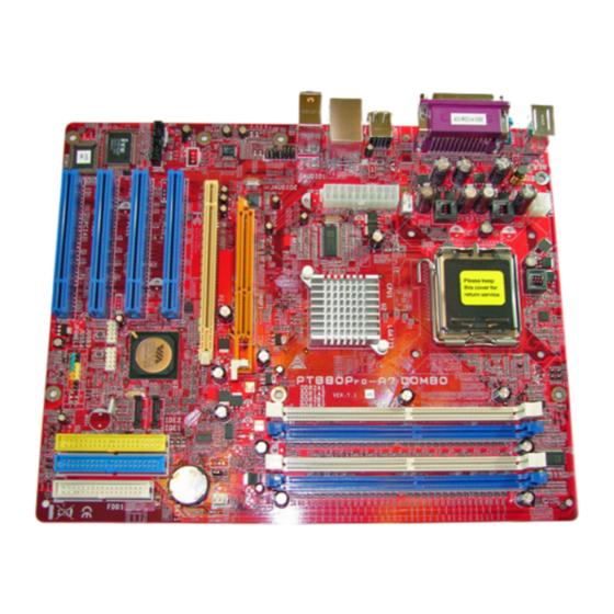
PT880 Pro-A7 DDR2 AYOUT AND OMPONENTS JKBMS1 JAUXPWR1 LGA775 JKBV1 CPU1 JCFAN1 (optional) JUSB1 JUSBV1 PT880 Pro JUSBLAN1 JATXPWR1 JAUDIO1 AGP1 CODEC BAT1 PCI1 JSATA2 JCDIN1 VT8237R PLUS JSPDIF_ OUT1 PCI2 JSATA1 JUSBV2 JCI1 JUSB2 JUSB3 Super I/O JCM OS1... -
Page 8: Chapter 2: Hardware Installation
PT880 Pro-A7 DDR2 CHAPTER 2: HARDWARE INSTALLATION (CPU) NSTALLING ENTRAL ROCESSING Special Notice: Remove Pin Cap before installation, and make goo d preservation for future use. When the CPU is removed, cover the Pin Cap on t he empty socket to ensure pin legs won’t be damaged. - Page 9 PT880 Pro-A7 DDR2 Step 2: Look for the black cut edge on socket, and the white dot on CPU should point wards this black cut edge. The CPU will fit only in the correct orientation. Step 2-1: Step 2-2: Step 3: Hold the CPU down firmly, and then close the lever to complete the installation.
-
Page 10: Fan Headers
PT880 Pro-A7 DDR2 FAN H EADERS These fan headers support cooling-fans built in the computer. The fan cable and connector may be different according to the fan manufacturer. Connect the fan cable to the connector while matching the black wire to pin#1. -
Page 11: Installing System Memory
PT880 Pro-A7 DDR2 NSTALLING YSTEM EMORY 1. Unlock a DIMM slot by pressing the retaining clips outward. Align a DIMM on the slot such that the notch on the DIMM matches the break on the Slot. 2. Insert the DIMM vertically and firmly into the slot until the retaining chip... -
Page 12: Connectors And Slots
PT880 Pro-A7 DDR2 ONNECTORS AND LOTS FDD1: Floppy Disk Connector The motherboard provides a standard floppy disk connector that supports 360K, 720K, 1.2M, 1.44M and 2.88M floppy disk types. This connector supports the provided floppy drive ribbon cables. IDE1/IDE2: Hard Disk Connectors... - Page 13 PT880 Pro-A7 DDR2 PCI1~PCI4: Peripheral Component Interconnect Slots This motherboard is equipped with 4 standard PCI slots. PCI stands for Peripheral Component Interconnect, and it is a bus standard for expansion cards. This PCI slot is designated as 32 bits.
- Page 14 PT880 Pro-A7 DDR2 AGP1: Accelerated Graphics Port Slot Your monitor will attach directly to that video card. This motherboard supports video cards for PCI slots, but it is also equipped with an Accelerated Graphics Port (AGP). An AGP card will take advantage of AGP technology for improved video efficiency and performance, especially with 3D graphics.
-
Page 15: Chapter 3: Headers & Jumpers Setup
PT880 Pro-A7 DDR2 CHAPTER 3: HEADERS & JUMPERS SETUP OW TO ETUP UMPERS The illustration shows how to set up jumpers. When the jumper cap is placed on pins, the jumper is “close”, if not, that means the jumper is “open”. - Page 16 PT880 Pro-A7 DDR2 JKBV1: Powe r Source Heade r for PS/2 Ke yboard and Mouse Pin 1-2 Close (default) +5V for PS/2 keyboard and mouse. Pin 2-3 Close PS/2 keyboard and mouse are powered by +5V standby voltage. Note: In order to support this func tion “Power-on s ystem via keyboar d and mouse”, “JKBV1”...
- Page 17 PT880 Pro-A7 DDR2 JAUXPWR1: Powe r Source Conne ctor for CPU Powe r Circuit By connecting this connector, it will provide +12V to CPU power circuit. Assignment +12V +12V Ground Ground JPANEL1: He ade r for Front Panel Facilities This 22-pin connector includes Power-on, Reset, HDD LED, Power LED, Sleep button, speaker and IrDA Connection.
- Page 18 PT880 Pro-A7 DDR2 JUSB2/JUSB3: Heade rs for USB 2.0 Ports at Front Panel This header allows user to connect additional USB cable on the PC f ront panel, and also can be connected with internal USB devices, like USB card reader.
- Page 19 PT880 Pro-A7 DDR2 JCI1: Chassis O pen Heade r This connector allows system to monitor PC case open status. If the signal has been triggered, it will record to the CMOS and show the message on next boot-up. Assignment Case open signal...
- Page 20 PT880 Pro-A7 DDR2 JSATA1/JSATA2: Se rial ATA Conne ctors The motherboard has a PCI to SATA Controller with 2 channels SATA interf ace, it satisfies the SATA 1.0 spec and with transfer rate of 1.5Gb/s. Assignment Ground JSATA1 T X+...
- Page 21 PT880 Pro-A7 DDR2 JSPDIF_O UT1: Digital Audio-out Conne ctors These connectors allow user to connect the PCI bracket SPDIF output or input header. Assignment SPDIF OUT Ground...
-
Page 22: Chapter 4: Useful Help
BIOS contents are corrupted. In this Case, please follow the procedure below to restore the BIOS: 1. Make a bootable floppy disk. 2. Download the Flash Utility “AWDFLASH.exe” from the Biostar website: www.biostar.com.tw 3. Confirm motherboard model and download the respectively BIOS from Biostar website. - Page 23 PT880 Pro-A7 DDR2 B. CPU Overheated If the system shutdown automatically after power on system for seconds, that means the CPU protection function has been activated. When the CPU is over heated, the motherboard will shutdown automatically to avoid a damage of the CPU, and the system may not power on again.
-
Page 24: Troubleshooting
PT880 Pro-A7 DDR2 ROUBLESHOOTING Problem Solution No power to the system at all Make sure power cable is Power light don’t illuminate, f an securely plugged in. inside power supply does not turn Replace cable. Contact technical support. Indicator light on key board does not turn on. -
Page 25: Chapter 5: Warpspeeder
PT880 Pro-A7 DDR2 WARPSPEEDER™ CHAPTER 5: NTRODUCTION [WarpSpeeder™], a new powerful control utility, features three user-friendly functions including Overclock Manager, Overvoltage Manager, and Hardware Monitor. With the Overclock Manager, users can easily adjust the frequency they prefer or they can get the best CPU performance with just one click. The Overvoltage Manager, on the other hand, helps to power up CPU core voltage and Memory voltage. -
Page 26: Installation
PT880 Pro-A7 DDR2 NSTALLATION 1. Execute the setup execution file, and then the following dialog will pop up. Please click “Next” button and follow the default procedure to install. 2. When you see the following dialog in setup procedure, it means setup is completed. -
Page 27: Warpspeeder™] Includes 1 Tray Icon And 5 Panels
PT880 Pro-A7 DDR2 ™] PEEDER INCLUDES TRAY ICON AND PANELS 1. Tray Icon: Whenever the Tray Icon utility is launched, it will display a little tray icon on the right side of Windows Taskbar. This utility is responsible for conveniently invoking [WarpSpeeder™] Utility. - Page 28 PT880 Pro-A7 DDR2 2. Main Panel If you click the tray icon, [WarpSpeeder™] utility will be invoked. Please refer to the following figure; the utility’s first window you will see is Main Panel. Main Panel contains features as follows: a. Display the CPU Speed, CPU external clock, Memory clock, AGP clock, and PCI clock information.
- Page 29 PT880 Pro-A7 DDR2 3. Voltage Panel Click the Voltage button in Main Panel, the button will be highlighted and the Voltage Panel will slide out to up as the following figure. In this panel, you can decide to increase CPU core voltage and Memory voltage or not.
- Page 30 PT880 Pro-A7 DDR2 4. Overclock Panel Click the Overclock button in Main Panel, the button will be highlighted and the Overclock Panel will slide out to left as the following figure. Overclock Panel contains the these features: a. “–3MHz button”, “-1MHz button”, “+1MHz button”, and “+3MHz button”: provide user the ability to do real-time overclock adjustment.
- Page 31 PT880 Pro-A7 DDR2 “Auto-overclock button”: User can click this button and [WarpSpeeder™] will set the best and stable performance and frequency automatically. [WarpSpeeder™] utility will execute a series of testing until system fail. Then system will do fail-safe reboot by using Watchdog function. After reboot, the [WarpSpeeder™] utility will restore to the hardware default...
- Page 32 PT880 Pro-A7 DDR2 6. About Panel Click the “about” button in Main Panel, the button will be highlighted and the About Panel will slide out to up as the following figure. In this panel, you can get model name and detail information in hints of all the chipset that are related to overclocking.
- Page 33 PT880 Pro-A7 DDR2 Note: Because the overclock, overvoltage, and hardware monitor features are controlled by several separate chipset, [WarpSpeeder™] divide these features to separate panels. If one chipset is not on board, the correlative button in Main panel will be disabled, but will not interfere other panels’...
-
Page 34: Appendix
PT880 Pro-A7 DDR2 APPENDIX: PCI-E VGA C ERTIFIED XPRESS The following PCI-Express VGA Cards are certificated to work with this motherboard. ASUS X300SE ASUS X550GE ASUS 5900 ELSA X850 ELSA X55 ELSA 6200 ELSA 6600 ELSA X700pro ELSA 6600GT Gigabyte X700... - Page 35 PT880 Pro-A7 DDR2 BIOS Setup BIOS Setup..................1 1 Main Menu....................3 2 Standard CMOS Features................6 3 Advanced BIOS Features................9 4 Advanced Chipset Features................. 16 5 Integrated Peripherals ................. 22 6 Power Management Setup................27 7 PnP/PCI Configurations................33 8 PC Health Status ..................
-
Page 36: Bios Setup
PT880 Pro-A7 DDR2 BIOS Setup Introduction This manual discussed Award™ Setup program built into the ROM BIOS. The Setup program allows users to modify the basic system configuration. This special information is then stored in battery-backed RAM so that it retains the Setup information when the power is turned off. - Page 37 PT880 Pro-A7 DDR2 PCI Bus Support This AWARD BIOS also supports Version 2.1 of the Intel PCI (Peripheral Component Interconnect) local bus specification. DRAM Support DDR2 SDRAM (Double Data Rate Two Synchronous DRAM) are supported. Supported CPUs This AWARD BIOS supports the Intel CPU.
-
Page 38: Main Menu
PT880 Pro-A7 DDR2 1 Main Menu Once you enter Award BIOS™ CMOS Setup Utility, the Main Menu will appear on the screen. The Main Menu allows you to select from several setup functions. Use the arrow keys to select among the items and press <Enter> to accept and enter the sub-menu. - Page 39 PT880 Pro-A7 DDR2 Integrated Peripherals This submenu allows you to configure certain IDE hard drive options and Programmed Input/ Output features. Power Management Setup This submenu allows you to configure the power management features. PnP/PCI Configurations This submenu allows you to configure certain “Plug and Play” and PCI options.
- Page 40 PT880 Pro-A7 DDR2 Set User Password If the Supervisor Password is not set, then the User Password will function in the same way as the Supervisor Password. If the Supervisor Password is set and the User Password is set, the “User” will only be able to view configurations but will not be able to change them.
-
Page 41: Standard Cmos Features
PT880 Pro-A7 DDR2 2 Standard CMOS Features The items in Standard CMOS Setup Menu are divided into 10 categories. Each category includes no, one or more than one setup items. Use the arrow keys to highlight the item and then use the<PgUp> or <PgDn> keys to select the value you want in each item. - Page 42 PT880 Pro-A7 DDR2 Main Menu Selections This table shows the selections that you can make on the Main Menu. Item Options Description Date mm : dd : yy Set the system date. Note that the ‘Day’ automatically changes when you set the date.
- Page 43 PT880 Pro-A7 DDR2 Item Options Description Halt On All Errors Select the situation in which No Errors you want the BIOS to stop All, but Keyboard the POST process and All, but Diskette notify you. All, but Disk/ Key Base Memory...
-
Page 44: Advanced Bios Features
PT880 Pro-A7 DDR2 3 Advanced BIOS Features Figure 3. Advanced BIOS Setup Boot Seq & Floppy Setup This item allows you to setup boot seq & Floppy. - Page 45 PT880 Pro-A7 DDR2 Hard Disk Boot Priority These BIOS attempt to load the operating system from the device in the sequence selected in these items. The Choices: Pri. Master, Pri.Slave, Sec.Master, Sec. Slave, USBHDD0, USBHDD1, USBHDD2 and Bootable Add-in Cards.
- Page 46 PT880 Pro-A7 DDR2 Shadow Setup Video BIOS Shadow Determines whether video BIOS will be copied to RAM for faster execution. Enabled (default) Optional ROM is enabled. Disabled Optional ROM is disabled. Cache Setup...
- Page 47 PT880 Pro-A7 DDR2 CPU L1&L2 Cache Depending on the CPU/chipset in use, you may be able to increase memory access time with this option. Enabled (default) Enable cache. Disabled Disable cache. CPU L3 Cache (This item will be hidden if CPU L3 is absent.) Depending on the CPU/chipset in use, you may be able to increase memory access time with this option.
- Page 48 PT880 Pro-A7 DDR2 TM2 Bus Ratio Represents the frequency. Bus ratio of the throttled performance state that will be initiated when the on-die sensor goes from not hot to hot. The Choices: 0X (default). TM2 Bus VID Represents the voltage of the throttled performance state that will be initiated when the on-die sensor goes from not hot to hot.
- Page 49 PT880 Pro-A7 DDR2 Quick Power On Self Test Enabling this option will cause an abridged version of the Power On Self-Test (POST) to execute after you power up the computer. Enabled (default) Enable quick POST. Disabled Normal POST. Boot Up NumLock Status Selects the NumLock.
- Page 50 PT880 Pro-A7 DDR2 Delay for HDD The Choices: 0 (default) Summary Screen Show This item allows you to enable/ disable display the Summary Screen Show. The Choices: Disabled (default), Enabled.
-
Page 51: Advanced Chipset Features
PT880 Pro-A7 DDR2 4 Advanced Chipset Features This submenu allows you to configure the specific features of the chipset installed on your system. This chipset manage bus speeds and access to system memory resources, such as DRAM. It also coordinates communications with the PCI bus. The default settings that came with your system have been optimized and therefore should not be changed unless you are suspicious that the settings have been changed incorrectly. - Page 52 PT880 Pro-A7 DDR2 To control the Clock/Drive. If you highlight the literal “Press Enter” next to the “DRAM Clock/Drive Control” label and then press the enter key, it will take you a submenu with the following options: DRAM Clock This item determines DRAM clock following 100MHz, 133MHz, 166MHz, 200MHz, 266MHz, 333MHz or By SPD.
- Page 53 PT880 Pro-A7 DDR2 Write to Read <TWtr> The Choices: 1T/2T, 2T/3T. Write Recovery Time<TWr> The Choices: 2T, 3T, 4T, 5T. DRAM BUS Selection The Choices: Auto (default), Single Channel, Dual Channel. RDSAIT/RDSBIT Mode The Choices: Auto (default), Manual. RDSAIT/RDSBIT Selection The Choices: 0~3F.
- Page 54 PT880 Pro-A7 DDR2 AGP Aperture Size Select the size of the Accelerated Graphics Port (AGP) aperture. The aperture is a portion of the PCI memory address range dedicated for graphics memory address space. Host cycles that hit the aperture range are forwarded to the AGP without any translation.
- Page 55 PT880 Pro-A7 DDR2 CPU & PCI Bus Control If you highlight the literal “Press Enter” next to the “CPU & PCI Bus Control” label and then press the enter key, it will take you a submenu with the following options: PCI Master 0 WS Write When enabled, writes to the PCI bus are executed with zero-wait states.
- Page 56 PT880 Pro-A7 DDR2 Memory Hole When enabled, you can reserve an area of system memory for ISA adapter ROM. When this area is reserved, it cannot be cached. Refer to the user documentation of the peripheral you are installing for more information.
-
Page 57: Integrated Peripherals
PT880 Pro-A7 DDR2 5 Integrated Peripherals Figure 5. Integrated Peripherals VIA OnChip IDE Device The chipset contains a PCI IDE interface with support for two IDE channels. Select “Enabled” to activate the first and / or second IDE interface. If you install a primary and / or secondary add-in IDE interface, select “Disabled”... - Page 58 PT880 Pro-A7 DDR2 OnChip SATA This option allows you to enable the onchip Serial ATA. The Choices: Enabled (default), Disabled. SATA Mode The Choices: IDE, RAID (default). IDE DMA Transfer Access The Choices: Enabled (default), Disabled. OnChip IDE Channel 0/1 The motherboard chipset contains a PCI IDE interface with support for two IDE channels.
- Page 59 PT880 Pro-A7 DDR2 VIA OnChip PCI Device OnChip PCI Device If you highlight the literal “Press Enter” next to the “ ” label and then press the enter key, it will take you a submenu with the following options: VIA-3058 AC97 Audio This option allows you to control the onboard AC97 audio.
- Page 60 PT880 Pro-A7 DDR2 USB Emulation The Choices: OFF (default), KB/MS, ON. Don’t support any USB device on DOS. KB/MS Support USB legacy KB and mouse, no support USB storage. Support USB legacy keyboard, mouse and storage. USB Keyboard/ Mouse Support This item allows you to enable or disable the USB Keyboard/ Mouse Legacy Support.
- Page 61 PT880 Pro-A7 DDR2 Onboard Parallel Port This item allows you to determine access onboard parallel port controller with which I/O Address. The Choices: 378/IRQ7 (default), 278/IRQ5, 3BC/IRQ7, Disabled. Parallel Port Mode The default value is SPP. The Choices: SPP (default) Using Parallel port as Standard Printer Port.
-
Page 62: Power Management Setup
PT880 Pro-A7 DDR2 6 Power Management Setup The Power Management Setup Menu allows you to configure your system to utilize energy conservation and power up/power down features. Figure 6. Power Management Setup ACPI function This item displays the status of the Advanced Configuration and Power Management (ACPI). - Page 63 PT880 Pro-A7 DDR2 There are four options of Power Management, three of which have fixed mode settings Min. Power Saving Minimum power management. Suspend Mode = 1 hr. HDD Power Down = 15 min Max. Power Saving Maximum power management only available for sl CPU’s.
- Page 64 PT880 Pro-A7 DDR2 Video Off Method This option determines the manner in which the monitor is goes blank. V/H SYNC+Blank (default) This selection will cause the system to turn off the vertical and horizontal synchronization ports and write blanks to the video buffer.
- Page 65 PT880 Pro-A7 DDR2 There are 3 options: “Former-Sts”, “On”, “Off”. “Off” (default) Means always set CMOS to the “Off” status when AC power is lost. “On” Means always set CMOS to the “On” status when AC power is lost “Former-Sts”...
- Page 66 PT880 Pro-A7 DDR2 USB Resume from S3 This item allows you to enable or disabled USB resume from S3. The Choices: Disabled (default), Enabled. When set to On, any event occurring at a VGA Port will awaken a system which has been powered down.
- Page 67 PT880 Pro-A7 DDR2 Resume Time (hh:mm:ss) You can choose the hour, minute and second the system will boot up. This field is only configurable when “RTC Resume” is set to “Enabled”. IRQs Activity Monitoring Press Enter to access another sub menu used to configure the different wake up events (i.e.
-
Page 68: Pnp/Pci Configurations
PT880 Pro-A7 DDR2 7 PnP/PCI Configurations This section describes configuring the PCI bus system. PCI, or Personal Computer Interconnect, is a system which allows I/O devices to operate at speeds nearing the speed of the CPU itself uses when communicating with its own special components. This section covers some very technical items and it is strongly recommended that only experienced users should make any changes to the default settings. - Page 69 PT880 Pro-A7 DDR2 Reset Configuration Data The system BIOS supports the PnP feature which requires the system to record which resources are assigned and protects resources from conflict. Every peripheral device has a node, which is called ESCD. This node records which resources are assigned to it. The system needs to record and update ESCD to the memory locations.
- Page 70 PT880 Pro-A7 DDR2 PCI / VGA Palette Snoop Choose Disabled or Enabled. Some graphic controllers which are not VGA compatible take the output from a VGA controller and map it to their display as a way to provide boot information and VGA compatibility.
-
Page 71: Pc Health Status
PT880 Pro-A7 DDR2 8 PC Health Status Figure 8. PC Health Status Shutdown Temperature This item allows you to set up the CPU shutdown Temperature. This item only effective under Windows 98 ACPI mode. The Choices: Disabled (default), 60℃/140F, 65℃/149F, 70℃/158F, 75℃/167F. - Page 72 PT880 Pro-A7 DDR2 stage. The item offers several delay time for you to choose. The Choices: Enabled (default), Disabled. Chassis Open Warning This item allows you to enable or disable Chassis Open Warning beep. The Choices: Disabled (default), Enabled.
-
Page 73: Frequency/ Voltage Control
PT880 Pro-A7 DDR2 9 Frequency/ Voltage Control Figure 9. Frequency/ Voltage Control CPU CLOCK RATIO The Choices: 8X (default), 9X, 10X, 11X, 12X, 13X, 14 X, 15X, 16X, 17X, 18X, 19X, 20 X, 21 X, 22 X, and 23X. CPU Voltage Regulator This item allows you to select CPU Voltage Control. - Page 74 PT880 Pro-A7 DDR2 Auto Detect PCI/DIMM CLK This item allows you to enable / disable auto Detect PCI Clock. The Choices: Enabled (default), Disabled.
Need help?
Do you have a question about the PT880 Pro-A7 DDR2 and is the answer not in the manual?
Questions and answers