Graco Quiet Bulldog 215-255 Instructions-Parts List Manual
Air motor
Hide thumbs
Also See for Quiet Bulldog 215-255:
- Instructions-parts list manual (25 pages) ,
- Instructions manual (20 pages)
Table of Contents
Advertisement
Quick Links
INSTRUCTIONS-PARTS LIST
178 mm (7 in.) DIAMETER
Quiet Bulldog Air Motor
FOR DRIVING BULLDOG PUMPS
7 bar (100 psi) Maximum Working Pressure
Part No. 215-255, Series G
Standard Quiet Air Motor.
Adapts to all existing Bulldog Pumps.
Includes auxiliary air exhaust port for use
in a Header System.
Part No. 237-001, Series A
Reduced Icing Quiet Air Motor.
Adapts to all existing Bulldog Pumps.
Table of Contents
. . . . . . . . . . . . . . . . . . . . . . . . . . . . . . . . . . . .
. . . . . . . . . . . . . . . . . . . . . . . . . . . . . . . . . . . .
. . . . . . . . . . . . . . . . . . . . . . . . . . . . . .
. . . . . . . . . . . . . . . . . . . . . . . . . . . . . . . . . . . .
. . . . . . . . . . . . . . . . . . . . . . . . . . . . . . . . . . . . .
. . . . . . . . . . . . . . . . . . . . . . . . . . . . . . . . . .
. . . . . . . . . . . . . . . . . . . . . . . . . . . . . . . . . . .
. . . . . . . . . . . . . . . . . . . . . . . . . . . . . . . .
. . . . . . . . . . . . . . . . . . . . . . . . . . . . . . . . . . . . .
. . . . . . . . . . . . . . . . . . . . . . . . .
GRACO INC. P.O. BOX 1441 MINNEAPOLIS, MN 55440-1441
This manual contains important
warnings and information.
READ AND RETAIN FOR REFERENCE
COPYRIGHT 1980, GRACO INC.
2-4
5
6-7
8-12
14-17
18
19
20
20
20
307-304
Supersedes G
and PCNs H, J, K and L
(includes Rev. M changes)
Model 215-255 Shown
Rev. N
Advertisement
Table of Contents

Related Manuals for Graco Quiet Bulldog 215-255


Summary of Contents for Graco Quiet Bulldog 215-255
-
Page 1: Table Of Contents
......Model 215–255 Shown GRACO INC. P.O. BOX 1441 MINNEAPOLIS, MN 55440–1441 COPYRIGHT 1980, GRACO INC. -
Page 2: Warnings
WARNINGS High Pressure Spray Can Cause Serious Injury. For Professional Use Only. Observe All Warnings. Read and understand all instruction manuals before operating equipment. FLUID INJECTION HAZARD General Safety Tip Guard (Spray Guns Only) This equipment generates very high fluid pressure. Spray Always have the tip guard in place on the spray gun while from the spray gun/dispensing valve, leaks or ruptured com- spraying. - Page 3 EQUIPMENT MISUSE HAZARD General Safety System Pressure Any misuse of the spray/dispensing equipment or accesso- Never exceed 7 bar (100 psi) air pressure to the motor, and ries, such as overpressurizing, modifying parts, using incom- never exceed the maximum working pressure of the com- patible chemicals and fluids, or using worn or damaged parts, plete pump, as stated in your separate pump manual.
- Page 4 Do not expose dure on page 2, to prevent the pump from starting acciden- Graco hoses to temperatures above 82 C (180 F) or below tally. Never operate the pump or air motor with the air motor –40 C (–40 F).
-
Page 5: Installation
2. Mount the air motor on resilient rubber pads, rather For additional help in designing your system, contact than sheet metal. Graco Technical Assistance (see back page). 3. Determine minimum air inlet pressure and pump Auxiliary Air Exhaust (Model 215–255) cycle rate to achieve desired spray/dispensing re- sults or minimum fluid pressure and flow. -
Page 6: Troubleshooting
Troubleshooting To restart a stalled motor, close the bleed-type master Locating Air Leaks air valve to bleed off all trapped air pressure. Turn the To locate where air is leaking, shut off the air supply air back on. This will trip the air valve of the air motor, and disconnect the hose. - Page 7 Troubleshooting Pack cavity with light waterproof grease. Grease packing (33*). Lips of packing (33*) must face up. K (18) H (9) D (53*) E (22) G (48*) F (17*) B (44) Model 215–255 Shown 33*, 37 C (16*) Fig. 3...
-
Page 8: Service
Service WARNING Pressure Relief Procedure To reduce the risk of serious bodily injury, including 5. Hold a metal part of the gun/valve firmly to the fluid injection, splashing in the eyes or on the skin, or side of a grounded metal pail, and trigger the injury from moving parts, always follow this proce- gun/valve to relieve pressure. - Page 9 Service Lubricate with light waterproof grease. Torque to 34 N.m (25 ft–lb). Torque to 12–16 N.m (9–12 ft–lb). Model 215–255 Shown Fig. 4...
- Page 10 Service 7. Pull up on the valve housing (23) to raise the trip 10. Remove the screws (14) and lockwashers (65) rod (63). Grip the rod below the bushing (45) with holding the air cylinder (27) to the base (61), and padded pliers.
- Page 11 Service 12. Check the bearing (T, see Fig. 3) in the air motor Reassembly base for wear. If wear is excessive, replace the 1. When replacing the trip rod assembly (63), lubri- base (61). cate the spring and rod with light waterproof grease.
- Page 12 Service 8. Make sure the mating faces of the manifold (29) b. For Model 237–001: Install the o-ring (18), lift and valve plates (25) are completely clean. Lubri- ring (26), screws (12), lockwashers (3), air in- cate the plates and place a seal (19) on each one, let fitting (56), air tube (83), mufflers (76), and then install the plates in the manifold (29).
- Page 13 Notes...
-
Page 14: Parts
Parts Model 215–255, Series G Standard Quiet Air Motor... - Page 15 Parts Model 215–255, Series G Standard Quiet Air Motor Part No. Description Part No. Description 104–029 CLAMP, grounding 176–564 ROD, piston 104–572 LOCKWASHER; 8 mm 161–556 GASKET; accopac 104–582 WASHER, tab 176–568 BUSHING, trip rod 215–933 BEARING, trip rod 176–569 NUT, trip rod 101–845 SCREW, pan hd, self-tapping;...
- Page 16 Parts Model 237–001, Series A Reduced Icing Quiet Air Motor 80, 81...
- Page 17 Parts Model 237–001, Series A Reduced Icing Quiet Air Motor Part No. Description Part No. Description 104–029 CLAMP, grounding 176–575 GASKET; cellulose fibre 104–572 LOCKWASHER; 8 mm 178–427 GUIDE, housing 104–582 WASHER, tab 178–426 HOUSING, spring 215–933 BEARING, trip rod 112–741 GASKET;...
-
Page 18: Accessories
Accessories USE GENUINE GRACO PARTS AND ACCESSORIES Grounding Wire and Clamp 222–011 Air Pressure Regulator Kit 207–651 7.6 m (25 ft) long, 21 bar (300 psi) Maximum Working Pressure 0–9 bar (0–125 psi) Regulated Pressure Range 1.5 mm (12 gauge) Includes air regulator 207–755 (see above),... -
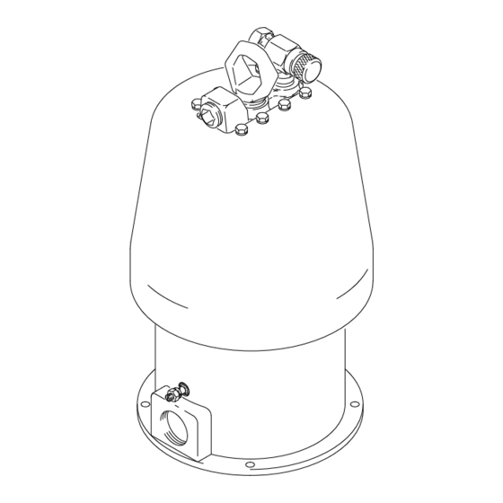
Page 19: Dimensions
Dimensions 3/4 npt(f) Swivel 3/4 npt(f) Swivel Air Inlet Air Inlet 1” npt(f) Auxiliary Air Exhaust Outlet Port 530 mm 532 mm (20.825 in.) (20.94 in.) 540 mm 540 mm (21.25 in.) (21.25 in.) -
Page 20: Technical Data
Graco distributor to the original purchaser for use. As purchaser’s sole remedy for breach of this warranty, Graco will, for a period of twelve months from the date of sale, repair or replace any part of the equipment proven defec- tive.
Need help?
Do you have a question about the Quiet Bulldog 215-255 and is the answer not in the manual?
Questions and answers