Graco 215-255 Instructions-Parts List Manual
Air motor
Hide thumbs
Also See for 215-255:
- Instructions-parts list manual (20 pages) ,
- Instructions manual (20 pages)
Advertisement
Quick Links
INSTRUCTIONS-PARTS LIST
This manual contains important
warnings and information.
READ AND KEEP FOR REFERENCE.
INSTRUCTIONS
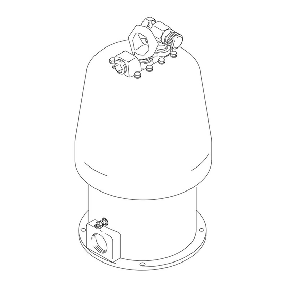
178 mm (7 in.) DIAMETER
Quiet Bulldog Air Motor
FOR DRIVING BULLDOG PUMPS
7 bar, 0.7 MPa (100 psi) Maximum Working Pressure
Part No. 215–255, Series G
Standard Quiet Air Motor.
Adapts to all existing Bulldog Pumps.
Includes auxiliary air exhaust port for use
in a Header system.
Part No. 237–001, Series A
Reduced Icing Quiet Air Motor.
Adapts to all existing Bulldog Pumps.
GRACO INC. P.O. BOX 1441 MINNEAPOLIS, MN 55440–1441
COPYRIGHT 1980, GRACO INC.
Graco Inc. is registered to I.S. EN ISO 9001
307–304
Supersedes Rev. N
Model 215–255 Shown
Rev. R
and PCN P
Advertisement

Related Manuals for Graco 215-255


Summary of Contents for Graco 215-255
- Page 1 Part No. 237–001, Series A Reduced Icing Quiet Air Motor. Adapts to all existing Bulldog Pumps. Model 215–255 Shown GRACO INC. P.O. BOX 1441 MINNEAPOLIS, MN 55440–1441 COPYRIGHT 1980, GRACO INC. Graco Inc. is registered to I.S. EN ISO 9001...
- Page 2 This equipment is for professional use only. Read all instruction manuals, tags, and labels before operating the equipment. Use the equipment only for its intended purpose. If you are not sure, call your Graco distributor. Do not alter or modify this equipment.
- Page 3 WARNING INJECTION HAZARD Spray from the gun/valve, leaks or ruptured components can inject fluid into your body and cause ex- tremely serious injury, including the need for amputation. Fluid splashed in the eyes or on the skin can also cause serious injury. Fluid injected into the skin might look like just a cut, but it is a serious injury.
- Page 4 WARNING FIRE AND EXPLOSION HAZARD Improper grounding, poor ventilation, open flames or sparks can cause a hazardous condition and re- sult in a fire or explosion and serious injury. Ground the equipment and the object being sprayed. Refer to Grounding on page 6. If there is any static sparking or you feel an electric shock while using this equipment, stop spray- ing/dispensing immediately.
- Page 5 Notes...
- Page 6 5. Object being sprayed: follow your local code. 6. Fluid supply container: follow your local code. NOTE: Always use Genuine Graco Parts and Acces- sories, available from your Graco distributor. 7. Solvent pails used when flushing: follow your local code.
- Page 7 Where possible, avoid using solid plumbing, which carries noise vibrations. For additional assistance in designing your system, Mount the air motor on resilient rubber pads, rather contact your Graco distributor. than sheet metal. Determine the minimum air inlet pressure and Auxiliary Air Exhaust (Model 215–255)
- Page 8 Troubleshooting To restart a stalled motor, close the bleed-type master To locate where air is leaking, shut off the air supply air valve to bleed off all trapped air pressure. Turn the and disconnect the hose. Screw the air inlet air back on.
- Page 9 Troubleshooting Pack cavity with light waterproof grease. Grease packing (33*). Lips of packing (33*) must face up. K (18) H (9) D (53*) E (22) G (48*) F (17*) B (44) Model 215–255 Shown 33*, 37 C (16*) Fig. 3...
- Page 10 Notes...
- Page 11 Service Pressure Relief Procedure 7. Open the pump drain valve (required in your system), having a container ready to catch the drainage. WARNING 8. Leave the drain valve open until you are ready to INJECTION HAZARD spray again. Fluid under high pressure can be in- jected through the skin and cause seri- If you suspect that the spray tip or hose is completely ous injury.
- Page 12 Service Disassembly 5. Remove the toggle retainers (47), o-rings (9), housing guides (51), springs (31), housings (52), and dowel pins (11). Do not drop the dowel pins. WARNING Take them out of the housing and check them for wear and damage. If the dowel pins are worn, To reduce the risk of serious injury whenever you replace them on both sides.
- Page 13 Service Lubricate with light waterproof grease. Torque to 34 N m (25 ft–lb). Torque to 12–16 N m (9–12 ft–lb). Tighten snugly. Do not exceed 2 N m (35 in-lb) Model 215–255 Shown Fig. 4...
- Page 14 Service 8. Pull up on the valve housing (23) to raise the trip 11. Remove the screws (14) and lockwashers (65) rod (63). Grip the rod below the bushing (45) with holding the air cylinder (27) to the base (61), and padded pliers.
- Page 15 Service 13. Check the bearing (T, see Fig. 3) in the air motor Reassembly base for wear. If wear is excessive, replace the 1. When replacing the trip rod assembly (63), lubri- base (61). cate the spring and rod with light waterproof grease.
- Page 16 Service 8. Make sure the mating faces of the manifold (29) b. For Model 237–001: Install the o-ring (18), lift and valve plates (25) are completely clean. Lubri- ring (26), screws (12), lockwashers (3), air cate the plates and place a seal (19) on each one, inlet fitting (56), air tube (83), mufflers (76), then install the plates in the manifold (29).
- Page 17 Notes...
- Page 18 Parts Model 215–255, Series G Standard Quiet Air Motor...
- Page 19 Parts Model 215–255, Series G Standard Quiet Air Motor Part No. Description Part No. Description 104–029 CLAMP, grounding 176–564 ROD, piston 104–572 LOCKWASHER; 8 mm 161–556 GASKET; accopac 104–582 WASHER, tab 176–568 BUSHING, trip rod 215–933 BEARING, trip rod 176–569 NUT, trip rod 101–845 SCREW, pan hd, self-tapping;...
- Page 20 Parts Model 237–001, Series A Reduced Icing Quiet Air Motor 80, 81...
- Page 21 Parts Model 237–001, Series A Reduced Icing Quiet Air Motor Part No. Description Part No. Description 104–029 CLAMP, grounding 176–575 GASKET; cellulose fibre 104–572 LOCKWASHER; 8 mm 178–427 GUIDE, housing 104–582 WASHER, tab 178–426 HOUSING, spring 215–933 BEARING, trip rod 112–741 GASKET;...
- Page 22 Notes...
- Page 23 Technical Data Maximum incoming air pressure ........... . 7 bar, 0.7 MPa (100 psi) Maximum recommended pump speed .
- Page 24 Graco distributor to the original purchaser for use. Graco will, for a period of twelve months from the date of sale, repair or replace any part of the equipment determined by Graco to be defec- tive.
- Page 25 Adapter; 1/2 npt x 1/2 btp (mbe) All written and visual data contained in this document reflects the latest product information available at the time of publication. Graco reserves the right to make changes at any time without notice. March 18, 1997...
Need help?
Do you have a question about the 215-255 and is the answer not in the manual?
Questions and answers