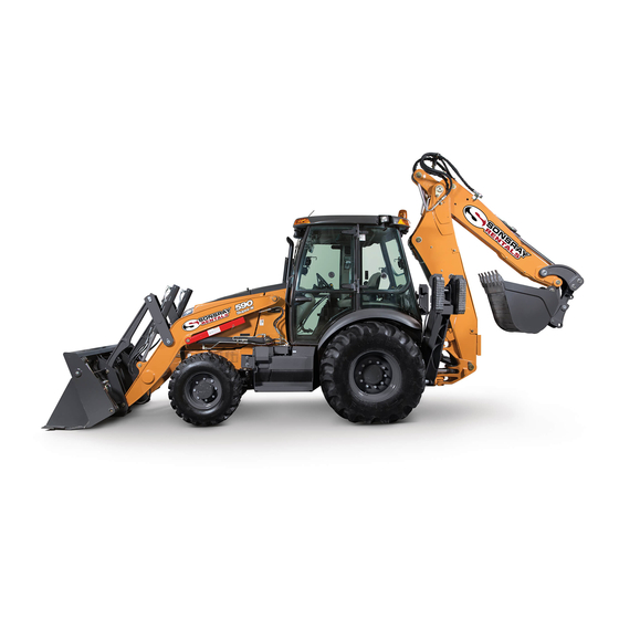
Summary of Contents for Case NHC740665
- Page 1 580SN WT 580SN 590SN Tier 4B (final) Tractor Loader Backhoe 580N PIN NHC740665 and above; 580SN WT PIN NHC745126 and above; 580SN PIN NHC743044 and above; 590SN PIN NHC746245 and above SERVICE MANUAL Part number 48194558 edition English October 2017...
- Page 2 SERVICE MANUAL 580N Four-Wheel Drive (4WD) Tier 4B (final) [NHC740665 - ], 580N Two-Wheel Drive (2WD) Tier 4B (final) [NHC740665 - ], 580SN Four-Wheel Drive (4WD) Tier 4B (final) [NHC743044 - ], 580SN Two-Wheel Drive (2WD) Tier 4B (final) [NHC743044 - ], 580SN WT Four-Wheel Drive (4WD) Tier 4B (final), Wide Track...
- Page 3 580N Two-Wheel Drive (2WD) Tier F5BFL413A*B007 4B (final) [NHC740665 - ] 580N Four-Wheel Drive (4WD) North America F5BFL413A*B007 Tier 4B (final) [NHC740665 - ] 580SN Two-Wheel Drive (2WD) North America F5BFL413A*B007 Tier 4B (final) [NHC743044 - ] 580SN Four-Wheel Drive (4WD)
- Page 4 Contents INTRODUCTION Engine..................10 [10.001] Engine and crankcase ............. 10.1 [10.103] Crankshaft and flywheel.
- Page 5 Thanks very much for your reading, Want to get more information, Please click here, Then get the complete manual NOTE: If there is no response to click on the link above, please download the PDF document first, and then click on it. Have any questions please write to me: admin@servicemanualperfect.com...
- Page 6 [27.120] Planetary and final drives ............27.3 Brakes and controls ..............
- Page 7 [41.101] Steering control ..............41.1 [41.200] Hydraulic control components.
- Page 8 [84.910] Boom ................84.3 [84.912] Dipper arm .
- Page 9 INTRODUCTION 48194558 20/10/2017...
- Page 10 Contents INTRODUCTION Foreword - Important notice regarding equipment servicing ........4 Safety rules .
- Page 11 General specification - Powertrain ............87 General specification - Hydraulics .
- Page 12 In any case, no warranty is given or attributed on the product manufactured or marketed by the manufacturer in case of damages caused by parts and/or components not approved by the manufacturer.
- Page 13 INTRODUCTION Safety rules Personal safety This is the safety alert symbol. It is used to alert you to potential personal injury hazards. Obey all safety messages that follow this symbol to avoid possible death or injury. Throughout this manual you will find the signal words DANGER, WARNING, and CAUTION followed by special in- structions.
- Page 14 INTRODUCTION Safety rules - Personal safety Unless otherwise instructed, always perform these steps before you service the machine: 1. Park the machine on a flat, level surface. 2. Place the backhoe in the transport position with the swing lock pin installed for transport. 3.
- Page 15 INTRODUCTION Safety rules - Ductile iron DANGER Altering cast ductile iron can cause it to weaken or break. Before you weld, cut, or drill holes on any part of this machine, make sure that the part is not cast ductile iron. Failure to comply will result in death or serious injury.
- Page 16 Improper disposal of batteries can contaminate the soil, groundwater, and waterways. CASE CONSTRUCTION strongly recommends that you return all used batteries to a CASE CONSTRUCTION dealer, who will dispose of the used batteries or recycle the used batteries properly.
- Page 17 Only use CNH Original Parts or CASE CONSTRUCTION Original Parts. Only genuine spare parts guarantee the same quality, duration, and safety as original parts, as they are the same parts that are assembled during standard production. Only CNH Original Parts or CASE CONSTRUCTION Original Parts can offer this guarantee.
- Page 18 W0111A Special tools The special tools that CASE CONSTRUCTION suggests and illustrate in this manual have been specifically re- searched and designed for use with CASE CONSTRUCTION machines. The special tools are essential for reliable repair operations. The special tools are accurately built and rigorously tested to offer efficient and long-lasting oper- ation.
- Page 19 INTRODUCTION Basic instructions - Fuse and relay locations The machine is equipped with easily accessible fuse and relay locations. Front console box 1. Turn the thumb screw (1) to loosen the panel cover (2) for the fuse box. Remove the panel cover. RCPH10TLB320AAF 2.
- Page 20 INTRODUCTION Front console ECU fuse and relay 1. Remove the cover from the steering column shroud. NOTE: The fuse and relay decal is on the underside of the steering column shroud cover. RCPH11TLB012BAD RAIL14TLB1061BA RAIL15TLB0001BA 48194558 20/10/2017...
- Page 21 INTRODUCTION Side console box 1. Turn the thumb screws (1) to loosen the panel cover (2) for the fuse box. Remove the panel cover. NOTE: The fuse and relay decal is on the underside of the cover. RCPH10TLB437AAF 2. Remove the fuse box covers as needed. RAIL14TLB1053BA 1.
- Page 22 INTRODUCTION 2. Locate the fuse and relay box. Refer to the decal for fuse, relay, and/or diode functions. RAIL15TLB0008BA Glow-plug Control Unit (GCU) fuse and dosing heater fuse 1. Raise the loader arm and engage the safety support. 2. Lift the engine hood. 3.


Need help?
Do you have a question about the NHC740665 and is the answer not in the manual?
Questions and answers