
Subscribe to Our Youtube Channel
Related Manuals for horsch Maestro RV


Summary of Contents for horsch Maestro RV
- Page 1 OPERATING INSTRUCTIONS Maestro RV TRANSLATION OF THE ORIGINAL OPERATING INSTRUCTIONS READ CAREFULLY PRIOR TO STARTING UP! KEEP OPERATING INSTRUCTIONS IN A SAFE PLACE! 60028570 • 01 • 04/2021 • en...
-
Page 3: Table Of Contents
Table of contents Table of contents 1 Introduction ............................Foreword ..............................Notes on representation........................... 1.2.1 Warning notes ..........................1.2.2 Instructions ..........................2 Safety and responsibility ........................10 Intended use ............................10 Operating Instructions ..........................10 Qualification of personnel ........................10 2.3.1 Groups of operators........................ - Page 4 Table of contents 5 Attachment............................33 Overview..............................33 Hydraulics ..............................34 5.2.1 Marking of hydraulic hoses ......................34 5.2.2 Coupling with Pronto AS / Focus TD..................... 36 Aluminium clips............................37 Lighting..............................38 Instruction stickers ........................... 39 6 Operation.............................. 42 Connecting / Parking ..........................42 6.1.1 Connecting ..........................
- Page 5 Table of contents 11 Optional equipment ..........................104 11.1 Micro-granular compound facility......................104 11.2 AutoForce ..............................105 11.3 Fertiliser flow monitoring ......................... 105 11.4 Bout marker ............................. 105 12 Troubleshooting............................108 13 Care and maintenance ..........................110 13.1 Maintenance overview ..........................110 13.1.1 After 10 operating hours ......................111 13.1.2 Before the season ........................
- Page 6 Maestro 8 Geschäftsführer Leiter Forschung & Entwicklung Maestro 12 Translation of EC Declaration of Conformity The manufacturer HORSCH Maschinen GmbH, Sitzenhof 1, D-92421 Schwandorf hereby declares that the product Drill unit Maestro 6 RV, Maestro 8 RV, Maestro 12 RV Type: this declaration refers to, conforms with all relevant fundamental health and safety requirements of the EC directive 2006/42/EC.
- Page 7 Please enter the corresponding data into the following list upon reception of the machine: Serial number: Machine type: Year of construction: Initial use: Accessories: Dealer address Name: Road: Place: Phone: Cust. No. Dealer: Cust. No. HORSCH 60028570 • 01 • 04/2021 • en...
-
Page 8: Introduction
Observe the safety notes! HORSCH will not assume liability for any damage or malfunctions resulting from fail- ure of complying with the operating instructions. Any person commissioned to performing tasks on or with the machine must read and apply the operating instructions. -
Page 9: Instructions
Introduction | 1 CAUTION Highlights a danger that can lead to injury if not avoided. Read all warning notes in these operating instructions! 1.2.2 Instructions NOTE Identifies important notes. Instructions for actions and their elements are marked by different symbols: ü... -
Page 10: Safety And Responsibility
• carrying out maintenance and/or repair work on a machine that has not been shut down or is not secured against restarting HORSCH does not assume any liability for damages resulting from the unintended use of the machine. 2.2 Operating Instructions... -
Page 11: Groups Of Operators
• Operation • Maintenance • Troubleshooting and repair Furthermore, for certain activities the corresponding personnel must have been Operator trained by trained by service personnel from HORSCH. HORSCH This refers to the following activities: • Loading and transport • Commissioning •... -
Page 12: Personal Protective Outfit
2 | Safety and responsibility 2.4 Personal protective outfit Missing or incomplete protective equipment increases the risk of health damage. Personal protective equipment includes, e.g.: Tight fitting clothes / protective clothing, possibly a hair net Safety shoes Safety gloves Safety goggles to protect the eyes against dust or spray, when working with fertil- iser or liquid fertiliser. -
Page 13: Safety In Operation
Ø The machine must only be put into operation after receiving instructions by employees of the authorized dealer or a HORSCH employee. All protective features and safety equipment, such as detachable protective devices (wheel chocks, etc.), must be correctly in place and reliably functioning before the machine is put into operation. -
Page 14: Hydraulics
2 | Safety and responsibility • Operating instructions of the tractor Ø Exercise special caution when reversing the tractor. Never stand between tractor and machine. Ø Only park the machine on a firm and level surface. Before unhitching the towed machine, lower it to the ground. Ø... -
Page 15: Technical Limiting Values
Safety and responsibility | 2 Ø Never leave or access the machine under overhead lines to avoid possible risks of electric shock or voltage flashover. Voltage flashover generates high electric voltages on the outside of the machine. What to do in case of This results in extreme voltage differences at the ground around the machine. -
Page 16: Changing Equipment / Wear Items
Structural changes not approved by HORSCH may affect the functionality and opera- tional safety of the machine and will void any warranty claim. HORSCH is not liable for damages to life and limb as well as property damages res- ulting from unapproved retrofitting and conversions. -
Page 17: Spare Parts
Spare parts and accessories which are not delivered by us have not been tested or approved by us. The installation or use of other than HORSCH products can therefore negatively af- fect the design characteristics of the machine and thus impair the safety of man and machine. -
Page 18: Danger Zone
All other maintenance and repair tasks, which are not described in the operating in- structions, must only be carried out by an authorized professional workshop or by an operator who has been trained by HORSCH for this purpose. 2.13 Danger zone... -
Page 19: Safety Stickers
Safety and responsibility | 2 2.14 Safety stickers Safety stickers on the machine warn of hazards at dangerous points and are an im- portant part of the safety equipment of the machine. Missing safety stickers increase the risk of severe or even fatal injuries. 1. - Page 20 2 | Safety and responsibility Stay clear of the operating range of foldable machine parts! 00380135 When connecting the machine and when operating the hy- draulics, no persons are allowed between the machines! 00380145 Shut the engine down and pull off the key before starting maintenance and repair work.
-
Page 21: Positions Of Safety Stickers
Safety and responsibility | 2 2.14.1 Positions of safety stickers The positions of the safety stickers depend on the equipment. Safety stickers with the addition "2x" can be found on either side of the machine. 60028570 • 01 • 04/2021 • en... -
Page 22: Commissioning
3 Commissioning NOTE These work activities may be carried out only by persons trained by HORSCH for this purpose. WARNING Increased danger of accidents during commissioning. Ø Observe the notes in the Safety chapter and familiarise yourself with the ma- chine! 3.1 Delivery... -
Page 23: Installation
Commissioning | 3 3.3 Installation Instruction of the operator and initial installation of the machine will be carried out by our service engineers or distributors. Any preceding use of the machine is prohibited! The machine can only be released for operation after the instruction session conduc- ted by service technicians or sales partners and after the operating instructions have been read. -
Page 24: Technical Data
4 Technical data 4.1 Technical data Maestro 6.70 RV 8.70 RV 12.45 RV 6.75 RV 8.75 RV 12.50 RV 6.80 RV 8.80 RV 6.30"RV 8.30"RV Transport width 3.00 m 3.00 m 3.00 m Transport height 3.00 m 3.90 m 3.90 m Length without seed 2.90 m 2.90 m (3.50 m... - Page 25 Technical data | 4 NOTE: • Deviations due to technical further development reserved. • The weight of the implement depends on the equipment; specification with minimum equipment. • The permissible transport heights and transport width for road traffic may differ from country to country.
-
Page 26: Type Plate
Data on the type plate: Made in Germany Maschinen GmbH Sitzenhof 1, D-92421 Schwandorf Tel.: +49 9431 7143-0 www.horsch.com Model designation Serial number Year of construction Weight Information on year of manufacture • Year of manufacture in VIN/Vehicle Identification Number (coded): Embossed when basic vehicle or undercarriage is manufactured •... -
Page 27: Requirements On The Tractor
Technical data | 4 4.3 Requirements on the tractor WARNING Risk of accident from overloading the tractor. Ø Observe the permissible values of the tractor for axle loads, total weight, tyre load bearing capacity and air pressure. Ø Verify the suitability of the tractor before commissioning. The tractor must meet the following requirements to be able to use the machine as intended: Implement attachment... - Page 28 4 | Technical data Pronto 6 AS attachment Maestro 8 RV / 12 RV Double acting control units • Hydraulic functions Filling auger dual-acting control units with adjustable • Fertiliser direct drive fan flow volume • Fan for direct drive vacuum Filling auger for single hopper Pressureless return flow (max.
- Page 29 Technical data | 4 Engine power Maestro 8.70 RV / 8.75 RV / 8.80 12.45 RV / 12.50 RV RV / 8.30" RV Tractor attachment (kW/ 110 / 150 125 / 170 Pronto 6 AS without Disc- 125 / 170 140 / 190 System (kW/HP) Pronto 6 AS with DiscSys-...
-
Page 30: Calculating The Ballasting
4 | Technical data 4.3.1 Calculating the ballasting The permissible total weight, the permissible axle loads and the tyre load bearing ca- pacity must not be exceeded when mounting or connecting implements. The front axle of the tractor must always be loaded with at least 20 % of the curb weight of the tractor. - Page 31 Technical data | 4 Calculations 1. Calculation of minimum front ballasting with rear implement: ∙ ( + ) − ∙ + 0,2 ∙ ∙ Enter the result into the table. 2. Calculation of minimum rear ballasting with front implement ∙ − ∙...
- Page 32 4 | Technical data Checking the calculations Check the calculated values additionally by weighing: Weigh the combination of tractor and towed or connected machine to determine the front and rear axle load. Compare the determined values with the calculated values. This includes: •...
-
Page 33: Attachment
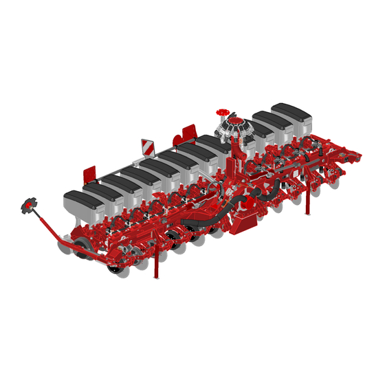
5 Attachment 5.1 Overview 1 Support 6 Bout marker 2 Implement attachment 7 Drill unit 3 Hydraulic cylinders for flaps 8 Lighting 4 Radar sensor 9 Fan vacuum 5 Fertiliser coulter 10 Fertiliser distributor tower WARNING Danger of injury Ø Do not look into the near range of the radar sensor. Ø... -
Page 34: Hydraulics
5 | Attachment 5.2 Hydraulics WARNING Risk of serious accidents and injuries from unintentional hydraulic movements! Ø Secure or lock the control units on the tractor. Ø Instruct persons to leave the slewing range of foldable machine parts. Ø Switch all control units to the locked position before switching on the tractor again. - Page 35 Attachment | 5 Folding Fan 3 Pressureless return CAUTION Damages on the hydraulic motor The return flow pressure on the fan drive must not exceed 5 bar. Bout marker Pressure gauge Coulter pressure 60028570 • 01 • 04/2021 • en...
-
Page 36: Coupling With Pronto As / Focus Td
5 | Attachment NOTE The following hydraulic movements are carried out via the hoses marked with +: Lift Folding Retraction of cultivation tools Fan flow 5.2.2 Coupling with Pronto AS / Focus TD Pronto 6 AS tail attachment 00380881 Fan flow Bout marker Fan return Seed wagon pressure gauge for coulter pressure... -
Page 37: Aluminium Clips
Attachment | 5 5.3 Aluminium clips The aluminium clips are plugged on the piston rods of hydraulic cylinders depending on the operating states. Different aluminium clips The thickness of the clips differs according to colour: Colour blue yellow black Silver Thickness 7 mm 10 mm... -
Page 38: Lighting
5 | Attachment 5.4 Lighting 7-pin plug Rear light, right Lamp, blinker Lamp, tail light Lamp, brake light Rear light, left Lamp, brake light Lamp, tail light Lamp, blinker Number Designation Colour Function yellow Blinker left 54 g white Earth green Blinker right 58 R... -
Page 39: Instruction Stickers
Attachment | 5 5.5 Instruction stickers 1. Clean soiled stickers. 2. Damaged or illegible stickers must be replaced immediately. 3. Apply the specified stickers to spare parts. Preload the folding hydraulics with min. 100 bar in the field. 00385214 Hydraulic coulter pressure 00385466 00385466 Display for coulter pressure... - Page 40 00386224 Loading hook Hook the load suspension gear (chains, ropes etc.) into this loading hook during loading. Loading work only by operators trained by HORSCH! 00380880 The locking bows of the adjustment bolts must point upwards. 00380527 L 00380527 R 00380527 Ensure correct installation of the rotor.
- Page 41 Attachment | 5 Check the tyre pressure at regular inter- vals, adapt if necessary - see mainten- ance overview. 00380109 Tighten with the appropriate torque. 60035021 Bout marker lock valve (1) Field use (2) Road travel 60034976 The return flow pressure on the fan drive must not exceed 5 bar.
-
Page 42: Operation
6 Operation WARNING Ø Whenever working on the machine pay attention to the associated safety notes in the chapter "Safety and Introduction" as well as the accident preven- tion regulations! 6.1 Connecting / Parking DANGER Serious accidents when manoeuvring and coupling! Ø... - Page 43 Operation | 6 NOTE Ø Observe the permissible total weight of the tractor or seed wagon, the max- imum lifting force, the permissible axle loads as well as the weight distribu- tion, see chapter Ballasting and Technical data. Ø Adjust the braces on the tractor link arms so that the tractor link arms are aligned parallel to the level ground.
-
Page 44: Transport Position
6 | Operation 7. Remove the Extra Power cable and connect it. Attach the protective cap. 8. Connect the lighting equipment. 9. When using a front hopper: Connect the hose for the fertiliser equipment tightly and firmly to the corresponding separating point. NOTE Switch between connection to seed wagon and connection to tractor The machine can only be operated with the respective intended equipment version... - Page 45 Operation | 6 3. Folding the machine in, see chapter Folding in. 4. Connecting to Pronto AS: Add the green aluminium clips to the hydraulic cylin- ders of the tractor link arm. Connecting to Focus TD/ST: Fill the piston rods of the hydraulic cylinders on the tractor link arm with aluminium clips.
-
Page 46: Parking
6 | Operation 6.1.3 Parking DANGER Serious accidents from loss of stability! Ø Park the machine only on a level and firm ground. Ø Secure the machine with wheel chocks against rolling away before unhitch- ing. Ø The machine has a negative drawbar load during the folding process and when the seed bar is not lowered. - Page 47 Operation | 6 3. Put the trap wheels in parking position; see chapter Trap wheel. 4. Lower the seed bar on the drill units and the supports. 5. Disconnect the hose for the fertiliser equipment from the seed wagon. 6. Depending on the equipment disconnect the hose for the micro-granulate fa- cility from the seed wagon.
- Page 48 6 | Operation Parking outdoors NOTE Damages from rain water entering the metering units and downpipes Ø Park the machine unfolded also in combination with a seed wagon. NOTE The trap rollers must not rest on the ground. They would otherwise soon be out of order because of standing damage.
-
Page 49: Folding
Operation | 6 6.2 Folding WARNING Serious crushing due to lowering / dropping machine parts Ø No persons may stay under raised machine parts. Ø Order persons to leave the danger zone around the machine. Make sure be- fore folding that no persons are present in the danger zone. Ø... -
Page 50: Folding In
6 | Operation 1. Switch on the E-Manager and select hydraulics Lift in the display. Connecting to seed wagon 2. Lift the machine completely. 3. Switch on the hydraulic Folding function in the display. 4. Unfold the machine to the stop position. Check the pre-tensioning pressure for the folding cylinder in the pressure gauge (minimum pressure 100 bar): 6.2.2 Folding in 1. -
Page 51: Use In The Field
Leave as many aluminium clips in place as required to keep the parallelogram on the drill units in horizontal position after lowering the machine in the field. Maestro RV for tractor attachment: Open the lock valve for the bout markers. Ø When connecting to a tractor: Adjust the support wheels so that the parallelogram on the drill units is parallel after lowering in the field (see chapter Adjusting the support wheels). -
Page 52: Checks
6 | Operation Work signal If the machine is connected directly to the tractor, sensors for the work signal are in- stalled on each of the second row from the outside (2nd and 7th/11th row). One of the sensors must trigger to activate the working signal. Work signal active In transport position the drill units hang down. -
Page 53: Adjusting The Support Wheels
Operation | 6 Working speed The appropriate working speed depends on the field conditions (soil type, harvest residues, etc.), the seed, seed quantity and other factors. 1. Reduce the working speed when the drill units run unsteady, in case of wet drilling conditions and on sticky soils. - Page 54 6 | Operation CAUTION Risk of injury from the unsecured support wheel falling down. Ø Secure the bolts again with cotter pin after the adjustment. NOTE In the lift-out positions (5 and 6) the single-disc fertiliser coulter, mounted to the console, has more space for adjustment. This allows putting them into parking posi- tion (without dismantling) or lifting them out completely.
-
Page 55: Position Of Control Units During Use In The Field
Operation | 6 Position of control units Connecting to tractor / Pronto 6 AS during use in the field Position Floating posi- Locked position Supply tion Control unit Unfolding / Folding in Fan XY Bout marker Connecting to Focus /TD/ST Position Floating posi- Locked position Supply... -
Page 56: Pneumatic System
7 Pneumatic system 7.1 Vacuum fan The hydraulic fan for vacuum generation is directly driven by the tractor hydraulics. The tractor must be equipped with a flow control valve to control the fan speed. The hydraulic pump must deliver sufficient oil to prevent the fan speed from drop- ping, even when the tractor speed drops or other hydraulic functions are activated. - Page 57 Pneumatic system | 7 Pressure gauge for vacuum (Focus TD) Pressure gauge (tractor connection) Vacuum Coulter pressure Folding pressure (pre-tension) Maintenance note The fan can be swivelled forward for maintenance and inspection. 1. Lower the machine on the coulter. 2. Dismantle the fan discharge (1) if fertiliser coulters are in place. 60028570 •...
-
Page 58: Fertiliser Distributor Tower
7 | Pneumatic system 3. Check whether the securing carbine (2) has been hooked in correctly. 4. Loosen the screw (3) and swivel the fan toward the front in a controlled man- ner. 5. Swivel the fan backward after maintenance and secure it with the screw. 6. -
Page 59: Fertiliser Fan
Pneumatic system | 7 7.3 Fertiliser fan See operating instructions for seed wagon concerning the pneumatic system for the fertiliser equipment. 7.3.1 Fan speeds The required fan speed depends on the fertiliser quantity. Travel speed, weight and shape of fertiliser in form of granules or powder and other factors also have an influence on the required air quantity. -
Page 60: Checks And Maintenance
7 | Pneumatic system 7.3.3 Checks and maintenance NOTE Ø The fan speed setting for fertiliser placement must be checked on all coulters before starting work and also at regular intervals when working on large areas. Ø Leak oil: Ensure a free flow return pressure of max. 5 bar. Ø... -
Page 61: Retightening The Fan Flange
Pneumatic system | 7 7.3.4 Retightening the fan flange The clamping taper fixates the fan wheel and additionally clamps on the drive shaft. The clamping taper on the fan drive may come loose. The impeller can thus move along the drive shaft and damage the fan. NOTE After approx. -
Page 62: Drill Unit
8 Drill unit NOTE Any changes and settings made on the assembly groups of the drill unit, which in- fluence the placement of seed or fertiliser, have an effect on the quality of the seed. Ø The placement of seed and fertiliser must therefore be checked when starting work, when making changes to settings and, when working on larger areas, also regularly in between. -
Page 63: Coulter Discs
Drill unit | 8 Filling the seed hopper WARNING Health risk due to absent protective outfit Ø Follow the information in the safety data sheets of the manufacturers about the substances used. Ø Wear personal protective outfit (e.g. Respirator FFP3). NOTE We recommend adding a mixture of talcum (80%) and graphite (20%) to the seed (see accessory pack of the machine). - Page 64 8 | Drill unit Coulter disc adjustment 1. Unscrew the depth guide wheels. See the depth guide wheels section. 2. Loosen the screws (1) and take them off together with the coulter disc. 3. Remove the spacer disc(s) (2). 4. Fasten the coulter disc again with the screw (1). Tighten the screws with 140 5.
- Page 65 Drill unit | 8 The support skid is especially suitable for sandy soils as well as small seeds (rape, sugar beets, etc.). Support skid The clearing unit can be installed or removed without dismantling the coulter discs: 1. Attach the special tool supplied to the hook of the clearing unit or the support skid and use it to pull out the clearing unit or the support skid: The coulter system 15″...
- Page 66 8 | Drill unit Trap roller Clearing unit / support skid 1. Adjust the position of the trap rollers if the coulter discs are worn: 2. When replacing the coulter discs move the trap roller down again (position 1). 60028570 • 01 • 04/2021 • en...
-
Page 67: Depth Guide Wheels
Drill unit | 8 8.1.3 Depth guide wheels During sowing the depth guide wheels must rest against the coulter disc and clean them. The position of the wheels to the coulter discs must be adapted, e.g. when readjust- ing the coulter discs. NOTE Ø... - Page 68 8 | Drill unit 8.1.3.1 Setting the drilling depth The drilling depth of the coulter discs is limited by the depth guide wheels. The drilling depth can be adjusted in 14 steps (approx. 1.5 to 9 cm when new). The drilling depth changes by approx. 0.6 cm per step. Depth setting Adjustment bolts Depth setting scale...
-
Page 69: Trap Rollers
Drill unit | 8 8.1.4 Trap rollers Once the grain exits the Downpipe, it is immediately picked up by the trap roller and pushed gently into the ground. The grain can now no longer jump out of position. Damage to the trap roller should therefore always be avoided. -
Page 70: Press Rollers
8 | Drill unit Ø Turn the trap roller around and insert it into the bracket from above, secure Parking position the bolt with a cotter pin. Ø Reduce the working speed, if necessary, to prevent the grains from jumping out of position in the furrow. - Page 71 Drill unit | 8 NOTE Adjusting the lever toward the rear increases the consolidation in four levels from 8 to 55 kg. Ø Set the spring pre-tension equally on all drill units. Check the coulter pressure and the seed placement with every change to the press rollers.
- Page 72 8 | Drill unit • recommended on very light soils Rubber press rollers – wide version Displacing the axle In case of blockage caused by stones or harvest residues, one of the two press rollers can be moved forward. The offset of the press rollers reduces the risk of blockage. Ø...
- Page 73 Drill unit | 8 Finger press wheel • Compaction through coulter discs and depth guide rollers are removed. Rubber narrow / spike press wheel • recommended on lighter locations • not for shallow seed (e.g. sugar beets) NOTE Ø Always use the spike press wheel in combination with the rubber press roller to limit the submersion depth.
- Page 74 8 | Drill unit The finger or spike press wheels are mounted offset to the rubber press rollers: Mounting finger and spike press wheels Direction of travel 1 Finger / spike press wheel 2 Fertiliser coulter 3 Rubber press roller 1.
-
Page 75: Clearing Stars (Option)
Drill unit | 8 The rollers shall run symmetrically over the seed furrow. 4. Adjust the distance of the spike or finger press wheels using the sleeves sup- plied. Distances (a) and (b) must be equal. The press roller must turn freely and may not collide with other components. - Page 76 8 | Drill unit 8.1.6.1 Clearing stars for single disc coulter Adjusting the working depth WARNING Serious crushing due to lowering / dropping machine parts. Ø Support the raised machine by appropriate means. Ø Do not work under the raised machine without proper safeguards. The position of the clearing starts is set on the hole pattern via the adjustment bolts.
- Page 77 Drill unit | 8 Limit toward the top (hard soil conditions) 3. Align and insert the adjustment bolt so that the upper bolt (1) points to the in- side and the lower bolt (2) to the outside: Limit toward the bottom (soft soil conditions) 4.
- Page 78 8 | Drill unit Fixed position 5. Align and insert the adjustment bolt so that both bolts point to the inside. 8.1.6.2 Clearing stars for twin disc fertiliser coulter Adjusting the working depth WARNING Serious crushing due to lowering / dropping machine parts. Ø...
- Page 79 Drill unit | 8 Limit toward the top; setting for hard conditions Limit toward the bottom; setting for soft conditions 1. To adjust, remove the bolt lock, lift the clearing star on the bracket, pull out the bolt, reinsert it in the new position and secure it. 2.
- Page 80 8 | Drill unit Floating clearing stars The clearing stars in the floating version are recommended for light and medium soils with alternating soil conditions. with depth guide With the floating design, depth guidance takes place via the additionally mounted plastic wheel.
-
Page 81: Coulter Pressure
9 Coulter pressure During drilling the drill unit's own weight presses the coulter discs into the ground until the depth guide rollers rest on the ground. The hydraulic cylinders for the coulter pressure transfer additional pressure on the drill units, see chapter Hydraulics. •... - Page 82 9 | Coulter pressure NOTE Refer to the associated operating instructions for the AutoForce coulter pressure control. In the area of the tractor tracks the drill units can be additionally pre-tensioned with Coulter pressure in tractor 2 or 4 springs. This can compensate the higher compaction caused by the tractor tracks tracks.
- Page 83 Coulter pressure | 9 Positions 1-4 1. Lift the machine. 2. Pull the bolt out of the spring holder. 3. Slide the spring holder with the spring to the desired position. 4. Insert the bolt in the new position. The locking bow must point upwards. 5.
-
Page 84: Airvac Single Grain Metering System
10 AirVac single grain metering system The metering system provides transport and correct distribution of the seed to the soil. In the metering unit the grains are separated via an electrically driven metering disc. 10.1 Overview Metering system 1 Pneumatic hose Vacuum 2 Row Module Planter (RMP) 3 Metering unit 4 Engine... -
Page 85: Metering Unit
The two LEDs on the housing indicate the motor status: • lit continuously: no fault • flashing: motor fault NOTE Ø In the event of a motor fault, enter the error code in the HORSCH Error codes app and follow the corresponding action instructions. 10.2.2 Metering unit CAUTION Risk of crushing on the metering unit! Ø... - Page 86 10 | AirVac single grain metering system Metering disc Separator Metering disc mounting (adjustable) Inspection flap 10 Outlet to downpipe Removable housing half / Vacuum side 11 Metering disk sealing lip with notch 12 Ejection wheel Operating principle The vacuum generated presses the grains against the rotating metering disc which transports them further.
- Page 87 AirVac single grain metering system | 10 • Grain feed gate The filling level in the area of the grain pick-up is controlled with the grain feed gate. Depending on the position of the grain feed gate, different quantities enter the area of grain pick-up.
- Page 88 10 | AirVac single grain metering system • Separator The contours on the separator (1) remove excess grains from the metering disc. In the ideal scenario, there is only one grain per hole on the metering disc following the separator. Variants: Execution Area of application...
-
Page 89: Downpipe
AirVac single grain metering system | 10 10.2.3 Downpipe After the grain transfer in the metering unit the grain drops through the downpipe into the ground. The sensor is the basis for monitoring the drilling process. The sensor detects each grain and reports it to the computers. - Page 90 10 | AirVac single grain metering system WARNING Risk of accident Ø Secure the machine against lowering and unexpected movements. Ø Staying under unsecured raised machine parts is prohibited. Ø Carry out work on raised machine parts only if they are mechanically suppor- ted with suitable means.
-
Page 91: Operating The Metering System
AirVac single grain metering system | 10 Because of its shape, the downpipe assumes an important function with grain place- ment. The downpipe must not be damaged or dirty. Dust deposits in the sensor window can adversely affect the signals on the sensor. This can be the reason for incorrect data (faults) in the computer. -
Page 92: Changing And Adjusting Components
10 | AirVac single grain metering system 5. Tighten screws only by hand when replacing components. Do not use power screwdrivers. 6. Do not damage the cables. 7. When assembling housing parts, join the individual parts correctly applying only slight pressure. 10.3.2 Changing and adjusting components Various quick change fixtures on the metering unit facilitate efficient conversion, ad- justment and maintenance. - Page 93 AirVac single grain metering system | 10 3. It must be approximately flush with the housing and the separator: An angle of rotation from one hole to the next (1) causes an axial feed of 0.16 mm. 4. Insert the cotter pin. NOTE If the cotter pin is not inserted, the metering disc will be pressed against the hous- ing during use and lock up!
- Page 94 10 | AirVac single grain metering system 5. Hold the metering disc against it and turn the rotary handle toward the left to the stop position (3). 6. Check the distance of the metering disc to the housing, see Adjusting the metering disc.
- Page 95 AirVac single grain metering system | 10 Separator 1. Press the leaf spring (1) down for assembly and dismantling and push on the separator: 2. The separator rests flush against the spring steel plate (2). Check for correct seating: Small seeds kit / scraper 1.
-
Page 96: Adjusting The Metering Unit
10 | AirVac single grain metering system 4. Thread the required scraper on the bottom and let it engage toward the top: 5. Check for firm seating and complete engagement. 6. Check the scraper for axial mobility on the screws; clean if necessary. 7. - Page 97 AirVac single grain metering system | 10 5. Verify the settings with the test program in the E-Manager, see section Check- ing. 6. After the test was successful, install the matching components on all drill units and perform the same settings on all metering units. 7.
- Page 98 10 | AirVac single grain metering system 19 x 2.5 mm 01244125 – 02 Sunflowers * 2 - 4 -17 to 1-1 ** (01244181) 1 row of holes (60029336) 1 row of holes (01240800) 19 x 3.0 mm 01244130 – 02 Sunflowers * 2 - 4 -17 to 1-1 **...
- Page 99 AirVac single grain metering system | 10 30 x 4.0 mm 01240740 – 01 Edible sunflowers 3 - 5 -17 to (01240781) 1 row of holes Sweet maize (01240800) 30 x 4.5 mm 01240745 Maize 5 - 6 -25 to (01240781) 1 row of holes (01240800)
- Page 100 10 | AirVac single grain metering system 96 x 3.0 mm 01242503 2 - 3 -30 to (01240782) 2 rows of holes (01240900) 96 x 4.0 mm 01242504 3 - 5 -30 to (01240782) 2 rows of holes (01240900) AirVac metering system settings table If necessary, add talcum-graphite mix, see section Single grain metering –...
-
Page 101: Cleaning The Metering Unit
AirVac single grain metering system | 10 NOTE Any changes to the metering unit can influence the placement accuracy. Pay attention to the evaluation and the display in the terminal, repeat the test se- quences in case of negative changes. When sowing soy, the seed is not correctly detected to 100% by the sensor. -
Page 102: Troubleshooting
10 | AirVac single grain metering system 5. Accumulation of seed or grain fragments between metering disc and housing (2,3). Dismantle the metering disc for cleaning. Possible causes: Distance between metering disc and housing too large, non- homogeneous or impure seed, high percentage of grain fragments, etc. 6. - Page 103 AirVac single grain metering system | 10 Possible problems and suggested solutions have been compiled in the Troubleshoot- ing table. If the cotter pin on the rotary handle has been shorn off or is missing, the metering Metering disc jammed disc is pushed against the housing and will jam against it.
-
Page 104: Optional Equipment
11 Optional equipment 11.1 Micro-granular compound facility Ø Refer to the operating instructions of the seed wagon. NOTE The pneumatic system of the Micro-granular compound facility is not monitored! Hoses and distributor of the Micro-granular compound facility must therefore be checked and cleaned before use and several times during use for leak tightness and deposits. -
Page 105: Autoforce
Optional equipment | 11 11.2 AutoForce See separate operating instructions AutoForce. NOTE The machine must be in the correct working position for AutoForce to function cor- rectly, see chapter Adjusting the seed bar: Ø The fertiliser tower must be aligned vertically. Ø... - Page 106 11 | Optional equipment 6.70 6.75 6.80 6.30" 30" 8.70 8.75 8.80 8.30" 30" 12.45 12.50 Adjusting the aggressiveness Bout marker disc adjustment 1. Adjust the aggressiveness of the bout markers according to the soil conditions. 2. Loosen the hexagon screws (1), adjust the bout marker disc by turning the off- set rod and retighten the hexagon screws (1).
- Page 107 Optional equipment | 11 Mount the bout marker weights on heavy soil to ensure positive penetration of the Bout marker weights discs into the soil. Depth limiter The optional depth limiter can be attached on very light soils. This prevents the disk from sinking in.
-
Page 108: Troubleshooting
12 Troubleshooting Fault Possible cause Remedy Too many faults Working speed too high Reduce working speed. Required grain frequency (grains/s) Reduce working speed. too high Vacuum too low Increase the pressure. Check lines and connections for leaks. Grain feed gate set incorrectly Set the grain feed gate correctly. - Page 109 Troubleshooting | 12 Fault Possible cause Remedy Seed capacity, grain Wrong number of holes of metering Enter the correct number of holes of the spacing or grain de- disc metering disc in the E-Manager under fruit posit faulty parameters. Wrong speed signal •...
-
Page 110: Care And Maintenance
The machine has been designed and built to offer maximum performance, economy and operator friendliness under a vast variety of operating conditions. Prior to delivery, the machine was checked at the factory and by the HORSCH sales partner to ensure the optional condition of the machine. -
Page 111: After 10 Operating Hours
Care and maintenance | 13 13.1.1 After 10 operating hours Maintenance location Work instructions Retighten all screw and plug- Even firmly tightened screw and hydraulic connections may loosen. in connections as well as the hydraulic connections. Retighten all wheel nuts initially after 10 hours or 50 km. -
Page 112: During The Season
13 | Care and maintenance 13.1.3 During the season Maintenance location Work instructions Interval Machine in general Frame and frame connecting Check condition and firm seating daily parts Drill unit Clamping plates of the drill When the rows are adjusted, retighten all screws, see section Clamp- 40 h units ing plates (torque 180 Nm). - Page 113 Care and maintenance | 13 Motor bearing and housing Check for condition and smooth running. prior to use cover Distributor tower Check distributor and hoses for damage and blockage, clean the dis- prior to use tributor. Metering unit, single grain with Downpipe Vacuum connection Check for fastening and leak tightness...
-
Page 114: At The End Of The Season
13 | Care and maintenance 13.1.4 At the end of the season Maintenance location Work instructions Complete machine Perform care and cleaning work; do not spray plastic parts with oil or similar. Spray the piston rods of the hydraulic cylinder with a suitable corrosion protection agent. -
Page 115: Lubricating The Machine
Care and maintenance | 13 13.3 Lubricating the machine Ø Lubricate the machine regularly and after each wash with a suitable grease gun. This ensures operability and reduces repair costs and downtimes. CAUTION Handling lubricants Lubricants and mineral oil products are no danger to health as long as they are used as instructed. -
Page 116: Clean The Machine
13 | Care and maintenance Bout markers – 2x Drill unit Lubrication points with the addition "2x" can be found on either side of the ma- chine. 13.4 Clean the machine Ø Clean the machine thoroughly at regular intervals and after the end of the sea- son. -
Page 117: Machine Storage
Care and maintenance | 13 Ø Open the cover on the drill frame and clean out thoroughly with compressed air. The frame serves the Vacuum distribution, it may therefore contain residues of seed or dressing. Ø Clean the downpipes with the brush. Ø... -
Page 118: Disposal
Attention must be paid to all valid regulations! Decommissioning and waste disposal must only be carried out by operators who have been trained by HORSCH. Contact a waste disposal company, if this should be necessary. 60028570 • 01 • 04/2021 • en... -
Page 119: Appendix
3. Combination Maestro RV with front hopper Partner FT; Maestro RV additional equipment AutoForce 4. Combination Maestro RV with seed wagon (Pronto AS / Focus TD / Focus ST) 5. Combination Maestro RV with seed wagon (Pronto AS / Focus TD / Focus ST);... - Page 120 15 | Appendix 1 Connecting to tractor Tractor Power supply connection Maestro RV Job computer (Master) ISOBUS connection 2 Combination Maestro RV with front hopper Partner FT Front hopper Front connection Tractor Rear connection Maestro RV Battery Job computer (Master, can be con-...
- Page 121 RV (additional equipment AutoForce) with front hopper Partner FT Front hopper Front connection Tractor Rear connection Maestro RV Battery Job computer (Master, can be con- 10 Power supply connection figured as Slave, see operating in- structions of the drill control) ISOBUS connection...
- Page 122 15 | Appendix 4 Combination Maestro RV with seed wagon Tractor ISOBUS connection Seed wagon Power supply connection Maestro RV Job computer (Master) Battery Connecting cable hook-up 5 Combination Maestro RV (additional equipment AutoForce) with seed wagon Tractor Power supply connection...
-
Page 123: Work And Speed Signal
• Radar signal from one of the towed machines: see E-Manager operating instruc- tions, section Partner. • 7-pole signal socket on the tractor (for combination Maestro RV Solo with front hopper Partner FT): see section Read cable working position. • GPS signal: see operating instructions for terminal and GPS antenna as well as section Read cable working position. - Page 124 15 | Appendix 3. Configure the sensor speed, PTO shaft speed and working position. List of parameters Cursor Speed Possible values for configuration: • "deactivated": No sensor measures the speed. • "Wheel sensor": A wheel sensor is connected to the terminal and must be calib- rated.
- Page 125 Appendix | 15 5. This screen appears: 6. To determine the 100 m method: Follow the sequence of actions on the ter- minal or enter the value manually. 7. Return to the vehicle profile. Calibration is completed. Working position Possible values for configuration: •...
- Page 126 7. Select inversion. 8. Return to the vehicle profile. Calibration is completed. HORSCH machine setting On the last configuration screen, set the speed source (1) on TECU wheel and the working position (2) to TECU. If the dots light up red, the settings in the tractor ECU are wrong and must be corrected.
- Page 127 Appendix | 15 Nominal status It is sufficient for the function of the cable between HORSCH machine and tractor to either set the configuration of one sensor (speed or working position) or of both sensors. 60028570 • 01 • 04/2021 • en...
- Page 128 Notes 60028570 • 01 • 04/2021 • en...
- Page 130 All details on technical specifications and illustrations are approximate and non-binding. Subject to technical product revisions.
Need help?
Do you have a question about the Maestro RV and is the answer not in the manual?
Questions and answers