horsch Maestro 24 SW AHL Operating Instructions Manual
Hide thumbs
Also See for Maestro 24 SW AHL:
- Operating instructions manual (149 pages) ,
- Operating instructions manual (90 pages)

Related Manuals for horsch Maestro 24 SW AHL


Summary of Contents for horsch Maestro 24 SW AHL
- Page 1 OPERATING INSTRUCTIONS Maestro 24 SW AHL TRANSLATION OF THE ORIGINAL OPERATING INSTRUCTIONS READ CAREFULLY PRIOR TO STARTING UP! KEEP OPERATING INSTRUCTIONS IN A SAFE PLACE! ART.: 8043 0226 ISSUE: 02/2018...
- Page 3 HORSCH: ..............Confirmation of receipt of machinery Warranty claims become only effective when the first use of the machine is reported to HORSCH Maschinen GmbH within a week. www.horsch.com under SERVICE PARTNERBEREICH an interactive PDF form is available for down- load for this purpose (not available in all languages).
- Page 4 Drill unit Machine type: from serial number: 24591296 Maestro 24 SW AHL this declaration refers to, conforms with all relevant fundamental health and safety requirements of the EC directive 2006/42/EC. For proper implementation of the health and safety requirements mentioned in the EC-directive,...
-
Page 6: Table Of Contents
Table of contents Introduction ...........4 Operation .............35 Foreword ............4 Commissioning / Tractor change ....35 Notes on representation .........4 Adjust the height of drawbar Service............5 eye/spherical cap ........35 Warranty claim processing ......5 Connecting/Parking ........35 Consequential damage........5 Connecting ...........35 Transport position .........37 Safety and accident prevention ....6 Parking ............38 Intended use ...........6... - Page 7 Single grain metering .........63 Single grain metering unit ......64 Overview ............64 Components in the metering unit ....66 Adjusting the metering unit ......73 Checks ............77 Problems and rectification ......78 Downpipe............80 Single grain coulter discs......82 Depth guide rollers ........83 Trap roller .............84 Setting the drilling depth .......85 Adjusting the coulter pressure ......87 Press rollers..........88...
-
Page 8: Introduction
DANGER to the safety notes! Highlights a danger that will lead to death or HORSCH will not assume liability for any dam- severe injury if it is not avoided. age or malfunctions resulting from failure of complying with the operating instructions. -
Page 9: Service
Service Consequential damage HORSCH Company would like you to be com- The machine has been manufactured by pletely satisfied with your machine and our HORSCH with greatest care. However, despite services. the intended use deviations in placing quantity up to total failure may be caused by e.g.: If you encounter any problems, please feel free to contact your sales partner. -
Page 10: Safety And Accident Prevention
Please read and comply with the following safety notes, before you start to use the machine! Horsch does not assume any liability for dam- ages resulting from the unintended use of the Intended use machine. -
Page 11: Qualification Of Personnel
The person must be physically able to keep sponding personnel must have been trained by ¾ the machine under control. service personnel from HORSCH. This refers to the following activities: The person is able to perform work with the ¾... -
Page 12: Children In Danger
Children in danger Safety in traffic Children are not able to assess dangers and may DANGER behave unpredictably. Children are therefore especially endangered: No passengers are allowed to ride on the machine! Keep children away from the machine. ¾ Especially before drive off and before trigger- ¾... -
Page 13: Safety In Operation
The machine must only be put into operation ¾ in severe accidents. after receiving instructions by employees of the authorized dealer or a HORSCH em- Caution with negative drawbar load! ployee. ¾ With an empty hopper and under certain op- The machine registration form must be com- ¾... - Page 14 HORSCH for this purpose. Hydraulic components on unsecured machine ¾ parts must not be dismantled.
- Page 15 Overhead lines Technical limiting values When unfolding or folding the wings, the ma- If the technical limiting values of the machine are chine may reach the height of overhead lines. not observed, the machine may get damaged. Possible voltage flashover to the machine caus- This can lead to accidents with severe or even ing fatal electric shock or fire.
-
Page 16: Fertiliser And Dressed Seed
Caution! Danger of injury caused by projecting ¾ parts (e.g. coulters)! HORSCH is not liable for damages to life and limb as well as property damages resulting from Assume ergonomic working postures with any ¾ unapproved retrofitting and conversions. -
Page 17: Care And Maintenance
Conform to prescribed schedules for repetitive ¾ by an operator who has been trained by tests or inspections. HORSCH for this purpose. Service the machine according to the ¾ maintenance plan, see chapter Care and maintenance. -
Page 18: Danger Zone
Danger zone Failing to pay attention to the danger zone can The area marked red indicates the danger zone result in severe or even fatal physical injuries. of the machine: Do not stand under lifted loads. Lower such ¾ loads to the ground first. Instruct persons to leave the danger zone ¾... -
Page 19: Safety Stickers
Safety stickers Safety stickers on the machine warn of hazards Clean soiled safety stickers. ¾ at dangerous points and are an important part Damaged or illegible safety stickers must be ¾ of the safety equipment of the machine. Miss- replaced immediately. ing safety stickers increase the risk of severe or Provide spare parts with the specified safety ¾... - Page 20 Loading hook; Secure the machine with wheel hook the load suspension gear (chains, chocks before uncoupling or ropes etc.) into this loading hook during parking. loading. 00381116 Keep sufficient safety distance to the slewing range of the machine. 00381117 Danger of poisoning - Never climb into the tank.
- Page 21 Position of the safety stickers (depending on equipment) Safety stickers with the addition “2x” can be found on either side of the machine.
-
Page 22: Structure
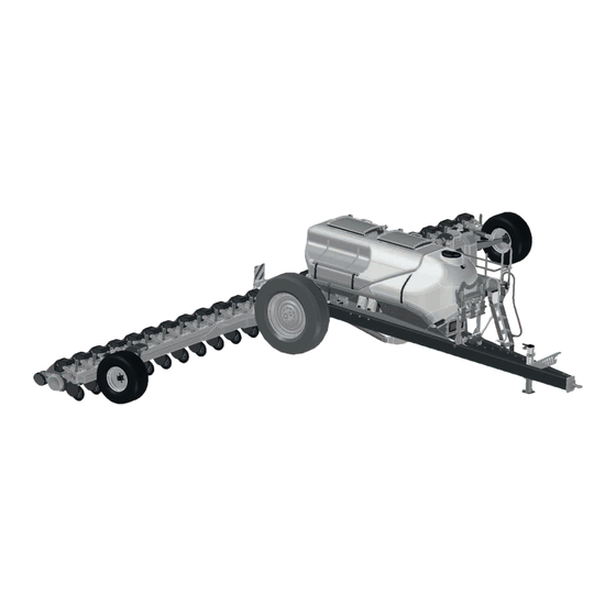
Structure Overview Maestro 24 SW ammonium nitrate - carbonyl diamide solution Access steps Support Vacuum fan Support wheel Hose bracket Liquid fertiliser system Lighting 10 Undercarriage tyres Seed hopper 11 Wheel sensor Fertiliser hopper DANGER Danger of serious accidents Transport rides on the machine, especially the steps (7) and platform are prohibited! WARNING Danger of injury... -
Page 23: Hydraulics
Hydraulics WARNING Accidental hydraulic movements (e.g. caused by passengers or children) can lead to severe accidents and injuries! Secure or lock the control units on the tractor. ¾ Instruct persons to leave the slewing range of ¾ foldable machine parts. Switch all control units to the locked position ¾... - Page 25 Fan – vacuum Tractor control unit Tractor hydraulic coupling Axial piston motor 10 cm³ Check valve Leak oil line...
- Page 26 Liquid fertiliser Centrifugal pump Pressure relief valve Filling neck Check valve Discharge pipe Valve block 2-way working valve Flow View System Nozzles (hose connection drawn only for one nozzle) Filter Control valve Hopper Flow meter Liquid fertiliser system – pump drive Tractor control unit Tractor hydraulic coupling Pressure gauge...
- Page 27 AutoForce 2-sectional G 3/8" G 3/8" G 3/8" G 3/8" G 3/8" G 1/4" SVP1 SVP2 G 1/2" ASB30 G1/4" Tractor hydraulic coupling Axial piston motor 10 cm³ Check valve Check valve Pressure gauge Restrictor ø 0.8 mm Valve block Pressure gauge Section 1 Pressure gauge Section 2 AutoForce hydraulic cylinder...
-
Page 28: Identification Of Hydraulic Hoses
Aluminium clips Identification of hydraulic hoses The symbol is always located above the hose The aluminium clips are placed on the piston that requires pressure to bring the machine in rods of hydraulic cylinders, depending on the transport position (lift out, folding, etc.). operating states, see chapter Operation. -
Page 29: Lighting
Lighting WARNING Traffic accidents caused by defective lighting. Ensure cleanliness and tight fit of the plug-and- ¾ socket connections. Check the lighting before setting off. ¾ Check warning boards and lighting equipment ¾ for cleanliness. 7-pin plug Rear light, right Lamp, direction indicator Lamp, tail light Lamp, brake light... -
Page 30: Instruction Stickers
Farben: schwarz Lfd. Nr. Stück Benennung Rohmaß Werkstoff og.Version: gepr. Sachb.: 1 : 1 Prog.Version: gepr. Sachb.: Maßstab: HORSCH Maschinen GmbH Allgemein- Werkstück- Sitzenhof 1 toleranz kanten arbeiter: geprüft: Bearbeiter: geprüft: Urheberschutz: Für diese technische Unterlage 92421 Schwandorf DIN 6784 Maschinen behalten wir uns alle Rechte vor. - Page 31 Tyre pressure Pressure gauge for liquid fertiliser pump pressure When adjusting leave, the locking bows of Pressure gauge for liquid fertiliser pressure the adjusting pins standing upright. Liquid fertiliser valve position Metering discs 1 Article number 1 Fertilising 2 Number of holes or slots 2 Filling / draining 3 Hole diameter or slot width ø...
- Page 32 Pressure gauge for Autoforce 2-sectional 1 Section 1: Area outside the tracks 2 Section 2: Area near the tracks Pressure gauge for Autoforce 4-sectional 1 Section 1 2 Section 2 3 Section 3 4 Section Area near the tracks...
-
Page 33: Technical Data
Technical data Maestro 24.70 SW ammonium nitrate - carbonyl diamide solution Transport width (m) 3.00 Transport height (m) 4.00 Transport length (m) 9.50 Weight incl. seed wagon from (kg) 11 830 Hopper capacity seed wagon seed / liquid fertilizer (l) 5 000 / 3 900 Filler opening seed wagon seed (mm) 800 x 660 (2x) -
Page 34: Type Plate
Type plate HORSCH Maschinen GmbH The type plate with the CE marking is located Sitzenhof 1, D-92421 Schwandorf Tel. +49 (0) 9431 / 7143-0 on the frame of the machine. Fax +49 (0) 9431 / 413 64 Data on the type plate:... -
Page 35: Requirements For The Tractor
Requirements for the tractor WARNING Risk of accident! Observe the permissible values of the tractor ¾ for axle loads, total weight, tyre load bearing capacity and air pressure. Verify the suitability of the tractor before com- ¾ missioning. The tractor must meet the following require- ments to be able to use the machine as intended: Implement attachment 24 SW... - Page 36 Hydraulics Maestro 24 SW Pressureless return flow (max. 5 bar) Number of dual-acting control units hydraulic functions vacuum (with adjustable flow rate) seed (with adjustable flow rate) Filling auger Delivery rate at 180 bar Vacuum (l/min) Seed (l/min) Liquid fertiliser (l / min) maximum system pressure (bar) Oil grade Mineral hydraulic oil...
- Page 37 9470 9470 3000 3180 16460...
-
Page 38: Commissioning
These work activities may be carried out only by The permissible dimensions and weights for ¾ persons trained by HORSCH for this purpose. transport must be complied with. The tractor must be large enough so that ¾... -
Page 39: Operation
Operation Connecting/Parking DANGER Whenever working on the machine pay attention to the associated safety There is a risk that persons may become notes in the chapter “Safety and crushed and severely injured between machine prevention of accidents” as well as and tractor! the accident prevention instructions! Instruct persons to leave the area between... - Page 40 Support WARNING The support is height-adjustable. With negative drawbar load the machine may tilt back and cause severe injury to persons. Unfold the crank and select the desired gear (1): ¾ Secure the coupling properly! ¾ - without load: Pull the crank out for fast gear.
-
Page 41: Transport Position
Make the following additional adjustments be- Transport position fore road transport: 1. Connecting the machine, see section Con- WARNING necting. Danger of road accidents caused by losing the 2. Folding the machine, see section Folding. machine or machine parts. 3. Switch off the E-Manager. Lock the control units mechanically or electri- ¾... -
Page 42: Parking
Parking NOTE Clean the machine and prepare properly ¾ DANGER before parking it for an extended period; see chapter Care and Maintenance. Serious accidents caused by the machine roll- ing away! Thoroughly clean hopper and fertiliser equip- ¾ ment. Fertiliser is aggressive and speeds up Before unhitching secure the machine with ¾... -
Page 43: Folding
Folding Unplug the brake lines, ISOBUS and light- ing and hook in the bracket. Attach the cover caps if so equipped. WARNING Crank down the support. Dropping or lowering machine parts can cause Unhitch the machine. severe crushing injuries etc.! Machines with drawbar eye: No persons may stay under raised machine ¾... -
Page 44: Menu "Folding
Menu “Folding” If the folding process “Unfold or folding” is U N F O L D I N G aborted, this warning will be displayed for a few seconds. The warning will remind you that the transport width will not be observed if the folding process is aborted. - Page 45 The warning reminds you of the railing on the access steps. The railing must be folded to transport position, I N G F O L D before folding up. This must be confirmed in the E-Manager before folding. Otherwise the wings or the railing may be damaged.
- Page 46 Lift the attached block. ¾ At 50° the two drill towers are automatically I N G ¾ F O L D folded in (30° with single disc fertiliser coulter). At 75° the lift function will stop and the wings ¾ start to fold in (82°...
- Page 47 Once the wings are in transport position, the ¾ axle adjustment is released. I N G F O L D The alert for driving at a speed of 2 - 10 km/h ¾ appears. When driving with this speed, the symbol for ¾...
-
Page 48: Unfolding
Unfolding Pay attention to the sequence of the following steps! NOTE Do not place any clips on the lift cylinders. The ¾ machine would not reach drilling position and not receive a work signal. Connecting the machine. ¾ Machine folded in Switch on the E-Manager. - Page 49 Press the button to extend the axle. The sym- ¾ bol becomes shaded green. I N G U N F O L D Extend the axle against the stop position. ¾ The support wheels are thereby automatically extended. The sensors will switch when the axle is ¾...
- Page 50 Press the button for lowering. The symbol ap- ¾ pears against a green background, and the block can be lowered. I N G U N F O L D At 50° the drill towers are automatically ex- ¾ tended. At 20° the “ ”...
-
Page 51: Use In The Field
Use in the field NOTE Check the seed placement on all coulters ¾ Connecting the machine, see Connecting. ¾ when beginning to work (after a few metres of Unfolding the machine, see Unfolding. drilling) and with larger fields also in between: ¾... - Page 52 Position of control units during use in the field Floating position Locked position Supply Position Control unit hydr. functions Fan - vacuum Fan SOD...
-
Page 53: Checks
Checks Drill unit Have the fitting metering discs been selected ¾ and installed in all metering units? NOTE Have all metering units been correctly se- ¾ Drilling must be checked when starting work lected or adjusted (outside scraper, inside ¾ and, in case of larger fields also regularly in scraper, grain feed gate)? between! -
Page 54: Aligning The Seed Bar
Aligning the seed bar Lift the seed bar. ¾ The seed bar must be adjusted to the soil condi- tions to allow adequate space for movement. The parallelograms must be positioned hori- zontally or with a downward tendency on level ground when the seed bar is lowered: Place the same number of spacers on the pis- ¾... -
Page 55: Pneumatic System
Pneumatic system Hopper The hopper has been designed as pressurized The pneumatic system in the machine consists hopper. Both hopper and attachment parts must of a be absolutely leaktight during use. Leaks lead to metering errors. Hopper ¾ fan installation for solid fertiliser. ¾... -
Page 56: Railing
Railing NOTE Check for leaktightness each time a lid has DANGER ¾ been opened with the fan running by simply Severe accident by falling down! listening or feeling with your hand around No passengers are allowed to ride on the step! the lid. -
Page 57: Fan - Vacuum
Fan - vacuum The hydraulic fan for vacuum generation is di- rectly driven by the tractor hydraulics. The tractor must be equipped with a flow control valve to control the fan speed. The hydraulic pump must deliver sufficient oil to prevent the fan speed from dropping, even when the tractor speed drops or other hydraulic functions are activated. -
Page 58: Seed On Demand System
Seed on Demand system Changing the screen There are 2 different screens available for dif- Seed on Demand means demand oriented con- ferent types of fruit: tinuous refilling of seeds from the central hopper (2000 litre) to the single grain metering units. sugar beet sorghum Ø1 mm... - Page 59 Changing settings NOTE Excessive fan speeds can cause blockage in The flap must then be tightly and firmly closed the upper area of the Seed on Demand elbows. ¾ again and the gate valve removed again. Reducing the fan speed. ¾...
-
Page 60: Retightening The Fan Flange
Retightening the fan flange Checks and maintenance Check all hoses and connections every day ¾ The clamping taper fixates the fan wheel and for leaktightness and firm seating. additionally clamps on the drive shaft. Check the screen for cleanliness, clean if ¾... -
Page 61: Liquid Fertiliser
Liquid fertiliser Filling the hopper Connect the hose for filling with the corre- The machine is equipped with liquid fertiliser to ¾ sponding quick release coupling (3). place the fertiliser in the seed furrow. Fill the hopper with an external pump. ¾... -
Page 62: Section Control
Section Control Flow View System The Section Control valves are controlled by the The Flow View System is used to display the flow E-Manager. They are activated and disabled at of the liquid fertiliser. the respective rows. The flow at the individual rows can be compared For more information refer to the operating in- by a floating ball inside a translucent pipe sec- structions for the E-Manager. -
Page 63: Enter The Quantity
Enter the quantity Example: Fertilised quantity: 380 l The quantity of fertiliser is controlled by the Displayed value: 372 l control valve (3) via the E-Manager. 372/380 ≈ 98% Access the second work screen in the E-Man- ¾ ager and enter the desired quantity (observe Original calibration factor 18.5: the unit of measure): 18.5 / (98/100) ≈... -
Page 64: Nozzles
Nozzles Two nozzle sizes are supplied with the machine, sizes 39 and 51. Size 39 is mounted on the machine. The system pressure should be in the range of 2-4 bar (30-60 psi) to ensure uniform distribution across all rows. Use a smaller nozzle if the system pressure ¾... - Page 65 ���� ∶= ����������������ℎ�������� ���� ���������������������������� ���� ���� ����/�������� ���� ���� ∶= ������������������������ ���� ������������������������ ���� ���� ���� / ℎ���� ���� ���� ���������������������������� ���� ���� ����/�������� ���� ���� ∶= ������������ ℎ ������������������������ ���� �������� ���� ���� �������� ���������������������������� ���� ���� ����/ℎ���� 2.
-
Page 66: Placement
Changing the placement position NOTE Always mount the nozzle discs so that the ¾ side labelled with numbers points to the nozzle outlet. Material: Rustproof steel Placement The fertiliser can optionally be placed in the seed furrow or behind the trap roller. 1 Connection for placement in the seed furrow 2 Connection for placement behind the trap roller 3 Quick release coupling... -
Page 67: Single Grain Metering
Single grain metering WARNING Health hazard; damage of electronic devices NOTE Persons with cardiac pacemakers: Observe ¾ minimum 20 cm distance of cardiac pace- Any changes and settings made on the assem- makers to the solenoid closures of the hoods. bly groups of the drill unit, which influence the Keep electronic devices and data carriers ¾... -
Page 68: Single Grain Metering Unit
Single grain metering unit NOTE Water entry and motor damage on the metering unit Do not wash the metering units with high ¾ pressure cleaners! The different components in the metering unit Metering unit are described first. Adjustment and checking of the metering unit NOTE are then described in the chapters Adjusting the metering unit and Checking adjustments. - Page 69 Opening the metering unit The metering unit is made of high precision components. Any disturbance caused by contamination, leaks in the vacuum system, moisture or wear have a negative effect on the drilling quality. When performing work on the metering unit strict cleanliness and greatest care in handling any parts of the equipment is of utmost importance.
-
Page 70: Components In The Metering Unit
21 x 4,00 Before starting drilling you should ask your 24018941 12 x 4.0 24018931 21 x 5,00 HORSCH Service for further metering discs. 24018940 12 x 5.0 24018910 21 x 5,00 24018942 12 x 5.0 chamfer 2.5 x 20°... - Page 71 Storing metering discs 95142087 50 x 1.5 95120752 50 x 2.0 The tool box is fitted with brackets for metering discs (1) and shims (2) that are not needed. 95120753 50 x 2.5 95120754 50 x 2.8 95120010 64 x 3.0 95110502 64 x 4.0 24018938...
- Page 72 Shims The sliding bridge is available in versions A and B. Shims (thickness 0.2 mm) can be inserted under In assembled condition these can be identified the backing discs to equalize tolerances. by the corner. Shim In case of an alarm because of too high a cur- rent demand (E-Manager) the cause may be too narrow a gap between metering disc and metering housing.
- Page 73 Grain feed cover Grain feed cover soy In the grain feed cover seed grains are fed by For soy we have a special grain feed cover the Seed On Demand fan to the metering unit. available. It is part of the Soy-Kit and must be exchanged against the currently installed cover.
- Page 74 Kit for small seed (sugar beets, Outside scraper sorghum) The outside scraper is available in two versions: with one or two notches. For small seed the following components must be exchanged because of the size of the seeds: Outside scraper (1) •...
- Page 75 Aufkleber sugar beet Lfd. Nr. Stück Benennung Rohmaß Werkstoff sorghum 1 : 1 Maßstab: HORSCH Maschinen GmbH Allgemein- Werkstück- Sitzenhof 1 toleranz kanten soy beans Urheberschutz: Für diese technische Unterlage 92421 Schwandorf DIN 6784 Maschinen behalten wir uns alle Rechte vor.
- Page 76 Grain feed gate Wear and inspection of inside scraper The inside scraper wears off in the area of the The grain feed gate regulates the grain filling marking and must be replaced in case of visible level in the metering unit. signs of wear.
-
Page 77: Adjusting The Metering Unit
Adjusting the metering unit NOTE Before starting drilling some adjustments must After choosing the metering discs one should be made to the metering unit; these may need ¾ strictly check the settings in E-Manager. to be adapted later during drilling. The selection and setting must be identical, At the beginning, take your time with the ma- otherwise drilling faults cannot be ruled out. - Page 78 95120754 95120753 95120752 TSW Sorghum (200,000 grains/ha, travel speed 8 km/h) - guide values 95120754 95120753 95120752 TSW Sorghum (400,000 grains/ha, travel speed 8 km/h) - guide values...
- Page 79 2. Selecting components and adjusting NOTE values. The data in the tables are guide values. Select and install matching sliding webs, inner ¾ Depending on seed, working speed and other scrapers and outer scrapers. factors further adaptations may be necessary For this purpose pay attention to the de- for fine tuning.
- Page 80 Notes on vacuum Checking the setting Before filling in seed, you should check the set- The possible vacuum range is specified in the ting on the metering unit. table. Does the metering disc match the seed and Depending on grain shape, weight, metering •...
-
Page 81: Checks
Checks Fill in seed. ¾ Place a container under the downpipe. ¾ Switch on the E-Manager and run the vacuum Inspection on one row using the test ¾ fan. program E-Manager Adjust the vacuum as specified in the table. ¾ Park the seed bar so that all drill units are in Start the test program in the E-Manager - see ¾... -
Page 82: Problems And Rectification
Inspection in the field Sowing soy Besides the setting in the metering unit, the When sowing soy, the seed is not correctly de- placing quality depends on further factors. This tected to 100% by the sensor. can be negatively influenced by: The placement must therefore strictly be inspect- ed in the field. - Page 83 Problem Cause Remedy Too many missed seeds Scraper set too aggressive Adjust the outside scraper more in direction 9 Feed gate incorrectly adjusted Adjust the grain feed gate Vacuum too low Increase the vacuum setting Increase the fan speed Check lines and connections for leaks Gap between metering disc and Remove a shim metering housing too big...
-
Page 84: Downpipe
Downpipe Guide the downpipe down at the front edge ¾ of the recess in the drill unit. Plug in the top locking bolt and secure it with After the grain transfer in the metering unit ¾ a cotter pin. the grain drops through the downpipe into the ground. - Page 85 Reminder every 20 hours NOTE In order to avoid faults caused by soiled sensors in the downpipes and an impairment of the seed Faults and double seeds are not evaluated for placement, the note “Clean downpipes every all fruit types. day and check function of trap rollers”...
-
Page 86: Single Grain Coulter Discs
Single grain coulter discs Scrapers All coulter discs are equipped with scrapers on With their wedge shaped arrangement the coul- either side. These scrapers prevents sticking ter discs open the seed channel for the seed and blocking of the coulter discs. placement. -
Page 87: Depth Guide Rollers
Depth guide rollers If the depth guide rollers need to be adjusted any further, unscrew the screw (3) and change the discs (4) in their assembly order as required. During drilling the depth guide rollers must touch and clean the coulter discs. Maintenance The position of the wheels to the coulter discs can be changed, if required. -
Page 88: Trap Roller
Aufkl. "Tiefeneinstellung Maestro" Bearb. 21.01.2014 Vorwerk Gepr. ab 2014 Norm (Zeichnungsnummer) Blatt Trap roller © Horsch Maschinen GmbH 00385613 Änderungen sind untersagt Adjustment bolt with sticker Index Änderung Datum Turn the trap roller around and insert it into Name Bemaßungen in mm... -
Page 89: Setting The Drilling Depth
Schrift auf weißem Grund Material: 3M 3690 mit Schutzlaminat Aufkleber Lfd. Nr. Stück Benennung Rohmaß Werkstoff 1 : 1 HORSCH Maschinen GmbH Maßstab: Allgemein Werkstück Sitzenhof 1 toleranz kanten 92421 Schwandorf Urheberschutz: Für diese technische Unterlage DIN 6784 Landwirtschaft aus Leidenschaft www.horsch.com... - Page 90 NOTE Hard moving rollers can displace the seeds in the furrow and thus cause uneven distribution. If the seed placement is adjusted deeper, you must check the coulter pressure. If necessary you must increase the coulter pressure in order to assure the drilling depth. NOTE The depth guide rollers must be sufficiently pressed against the ground and the wheels must...
-
Page 91: Adjusting The Coulter Pressure
Adjusting the coulter With the two bores in the bracket and the two bores in the parallel guide the coulter pressure pressure can be increased in 4 steps. Front possibility = Pos. 1 During drilling the weight of the frame presses Rear possibility = Pos. -
Page 92: Press Rollers
Press rollers The open spring end must face to the rear. With their V-shaped arrangement the press rollers close the seed channel and press the soil against the seed. With the adjustment lever the consolidation ef- fect of the press rollers can be matched to soil conditions and drilling depth. - Page 93 Variants Rubber press rollers – wide version Width 50 mm Select between different press rollers depending • on the type of soil: Gap 7 mm • suitable for sorghum and sugar beets • Rubber press rollers – narrow version • recommended on very light soils Rubber press rollers –...
- Page 94 Rubber narrow / spike press roller Displacing the axle In case of blockage caused by stones or harvest Compaction through coulter discs and depth • residues, one of the two press rollers can be guide rollers are removed. moved forward. recommended on lighter locations •...
- Page 95 Mounting finger and spike press rollers The finger or spike press rollers are mounted offset to the rubber press rollers: The rollers shall run symmetrically over the seed furrow. Adjust the distance of the spike or finger press ¾ rollers using the sleeves supplied. Distances (a) and (b) must be equal.
-
Page 96: Clearing Stars (Option)
Clearing stars (option) Adjusting the height Adjust all clearing stars equally. The clearing stars clear stones and larger lumps Secure the machine against rolling, lift it and of soil out of the drilling range. The blade shape ¾ support it with proper jacks. produces a cutting effect for high portions of organic substances. - Page 97 Floating clearing stars with depth guide With the floating design, depth guidance takes place via the additionally mounted plastic wheel. The clearing stars can adapt to the soil contours through the missing restriction toward the top. NOTE The clearing stars in the floating version are recommended for light and medium soils with alternating soil conditions.
-
Page 98: Troubleshooting Maestro
Troubleshooting Maestro Malfunction Possible cause Remedy One row does not drill Foreign objects in seed hopper or Clean seed hopper and metering metering unit unit Vacuum connection interrupted Check vacuum connection and hose Motor defective Replace the motor The drill unit stops Foreign object in metering unit Cleaning the metering unit Too many faults... -
Page 99: Optional Equipment
Optional equipment AutoForce See separate operating instructions AutoForce. ContourFarming NOTE With cornering the rows on the outside of the curve must travel a longer distance in the same amount of time than on the inside. The speeds and thus the seed placement quantities (grains/ ha) are therefore different in all rows. -
Page 100: Care And Maintenance
Care and Cleaning Maintenance When performing cleaning work you should always wear the necessary protective outfit to protect your health and safety. WARNING NOTE Risk of injuries during maintenance work Do not clean electrical components, all hy- Please observe the safety notes on care and ¾... -
Page 101: Maintenance Intervals
Maintenance intervals NOTE The maintenance intervals are determined by Do not spray plastic parts with lubricants or many different factors. ¾ rust remover. These parts would become For example, the different operating conditions, brittle and break. weather impact, travel and working speeds, dust accumulation and type of soil, seed, fertiliser and dressing used, etc. -
Page 102: Maintenance Overview Maestro 16/24/36 Sw
Maintenance overview Maestro 16/24/36 SW Maintenance location Work instructions Interval After 10 operating hours Retighten all screw and plug-in Even firmly tightened screw connections can come loose (e.g. Once connections as well as the hydraulic because of material settlement or paint residues between the connections. - Page 103 Maintenance location Work instructions Interval Electrics Electrical lines Check for damage 40 h Ball-and-socket coupling Before connecting: Clean ball andspherical cap. daily Replace the foam ring if damaged and/or heavily soiled. daily Place the foam ring. daily Check ball and spherical cap for wear. The wear limit has 40 h been reached when the gauge rests fully on the ball or enters the spherical cap.
- Page 104 Maintenance location Work instructions Interval Drawbar eye Fastening ¾ Check mounting screws for firm seat (560 Nm) 40 h Wear ¾ Replace the component concerned if one of the wear limits 40 h has been exceeded or fallen short of (workshop work): Nominal Wear dimension Designation...
- Page 105 Maintenance location Work instructions Interval Wheels Undercarriage SW Check state and fastening 40 h Re-tighten the wheel nuts - see above Check air pressure 40 h (LI: = Load index) 10.0/75 - 15,3 6,0 bar 400/70 - 24 3.5 bar 520/85 R42 (LI 167 A8) 2.8-3.0 bar 550/60 - 22.5 2.8 bar...
-
Page 106: Lubrication Points
Lubrication points Maintenance location Work instructions Interval Lubrication points (Lubrication grease: DIN 51825 KP/2K-40) - Number of lubrication points in brackets Lift arm bolt Lubricate bolt wing mounting Sliding axle undercarriage lubricate (4) - extend the axle and apply grease to the Sliding axle seed bar Apply grease to top of axle Parallel guide of drill units... - Page 107 Bolt wing mounting (2x) Filling auger Parallel guide and depth guidance Single disc coulter for fertiliser Seed bar sliding axle (16 SW / 24.50 SW) (2x) Propshaft in case of fan drive with PTO-shaft...
- Page 108 Lift arm (2x) Support wheel mounting (2x) Wheel hub - support wheel (2x)
-
Page 109: Waste Disposal
Attention must be paid to all valid regulations. Decommissioning and waste disposal must only be carried out by operators who have been trained by HORSCH. Contact a waste disposal company, if this should be necessary. -
Page 110: Appendix
Appendix Tightening torques NOTE The tightening torques only serve as guidelines and are generally valid. Actual data given at the • corresponding points in the operating instructions have priority. Screws and nuts must thereby not be treated with lubricant, since this would change the friction value. •... - Page 111 Inch screws Tightening torques - inch screws in Nm Screw Strength 2 Strength 5 Strength 8 diameter No marks on head 3 marks on head 6 marks on head Inch Coarse Fine thread Coarse Fine thread Coarse Fine thread thread thread thread 12.2...
-
Page 112: Index
Index Accessories 6 Emptying residues 54 Accident prevention 6 Emptying the metering unit 65 Adjustable drawbar 31 Environment 105 Adjusting the consolidation 88 Adjusting the coulter pressure 87 Adjusting the metering unit 73 Fan flange 56 Aluminium clips 24 Fan - vacuum 53 Fertiliser 12 Flange 56 Backing disc 67... - Page 113 Speed 9 Outside scraper 70 Spherical ball 35 Overhead lines 11 Spherical cap 99 Step 11 Stickers 26 Packer 12 Storage 39,97 Parking 38 Piston rod 97 Plastic parts 97 Technical data 29 Plug 25 Top speed 9 Pneumatic system 51,100 Tractor change 35 Press roller 29 Traffic 8...
- Page 115 All details on technical specifications and pictograms are approximate and for information only. Subject to technical product revisions. HORSCH Maschinen GmbH Tel.: +49 94 31 7143-0 Sitzenhof 1 Fax: +49 94 31 7143-9200 92421 Schwandorf E-Mail: info@horsch.com www.horsch.com...
Need help?
Do you have a question about the Maestro 24 SW AHL and is the answer not in the manual?
Questions and answers