
Related Manuals for horsch Maestro RX


Summary of Contents for horsch Maestro RX
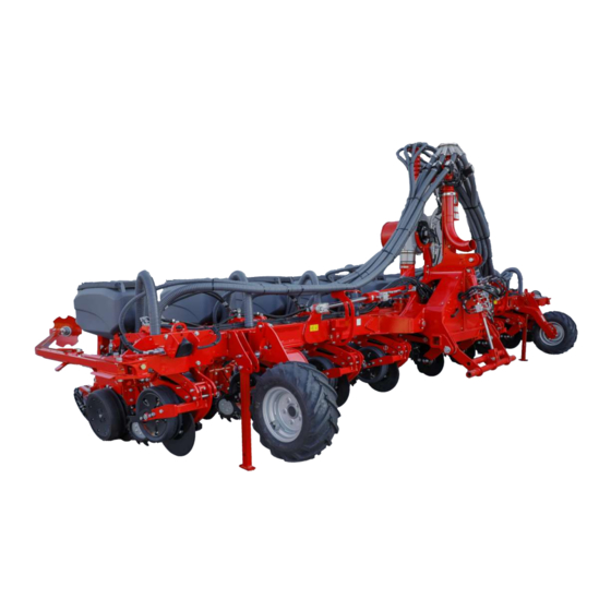
- Page 1 OPERATING INSTRUCTIONS Maestro RX TRANSLATION OF THE ORIGINAL OPERATING INSTRUCTIONS READ CAREFULLY PRIOR TO STARTING UP! KEEP OPERATING INSTRUCTIONS IN A SAFE PLACE! 60026626 • 01 • 01/2021 • en...
-
Page 3: Table Of Contents
Table of contents Table of contents 1 Introduction ............................Foreword ..............................Notes on representation........................... 1.2.1 Warning notes ..........................1.2.2 Instructions ..........................2 Safety and responsibility ........................10 Intended use ............................10 Operating Instructions ..........................10 Qualification of personnel ........................10 2.3.1 Groups of operators........................ - Page 4 Table of contents 6 Operation.............................. 36 Connecting / Parking ..........................36 6.1.1 Connecting ..........................36 6.1.2 Transport position........................37 6.1.3 Parking ............................39 Folding..............................40 6.2.1 Unfolding............................. 41 6.2.2 Folding in............................. 41 Use in the field ............................41 6.3.1 Please note ..........................41 6.3.2 Checks ............................
- Page 5 Table of contents 13 Care and maintenance .......................... 94 13.1 Maintenance overview ..........................94 13.1.1 After 10 operating hours ......................95 13.1.2 Before the season ........................95 13.1.3 During the season........................96 13.1.4 At the end of the season......................98 13.2 Clamping plates............................
- Page 6 Maestro 9 Geschäftsführer Leiter Forschung & Entwicklung Maestro 12 Translation of EC Declaration of Conformity The manufacturer HORSCH Maschinen GmbH, Sitzenhof 1, D-92421 Schwandorf hereby declares that the product Drill unit Maestro 8 RX, Maestro 9 RX, Maestro 12 RX Type: this declaration refers to, conforms with all relevant fundamental health and safety requirements of the EC directive 2006/42/EC.
- Page 7 Please enter the corresponding data into the following list upon reception of the machine: Serial number: Machine type: Year of construction: Initial use: Accessories: Dealer address Name: Road: Place: Phone: Cust. No. Dealer: Cust. No. HORSCH 60026626 • 01 • 01/2021 • en...
-
Page 8: Introduction
Observe the safety notes! HORSCH will not assume liability for any damage or malfunctions resulting from fail- ure of complying with the operating instructions. Any person commissioned to performing tasks on or with the machine must read and apply the operating instructions. -
Page 9: Instructions
Introduction | 1 CAUTION Highlights a danger that can lead to injury if not avoided. Read all warning notes in these operating instructions! 1.2.2 Instructions NOTE Identifies important notes. Instructions for actions and their elements are marked by different symbols: ü... -
Page 10: Safety And Responsibility
• carrying out maintenance and/or repair work on a machine that has not been shut down or is not secured against restarting HORSCH does not assume any liability for damages resulting from the unintended use of the machine. 2.2 Operating Instructions... -
Page 11: Groups Of Operators
• Operation • Maintenance • Troubleshooting and repair Operator trained by Furthermore, for certain activities the corresponding personnel must have been trained by service personnel from HORSCH. HORSCH This refers to the following activities: • Loading and transport • Commissioning •... -
Page 12: Personal Protective Outfit
2 | Safety and responsibility 2.4 Personal protective outfit Missing or incomplete protective equipment increases the risk of health damage. Personal protective equipment includes, e.g.: Tight fitting clothes / protective clothing, possibly a hair net Safety shoes Safety gloves Safety goggles to protect the eyes against dust or spray, when working with fertil- iser or liquid fertiliser. -
Page 13: Safety In Operation
Ø The machine must only be put into operation after receiving instructions by employees of the authorized dealer or a HORSCH employee. All protective features and safety equipment, such as detachable protective devices (wheel chocks, etc.), must be correctly in place and reliably functioning before the machine is put into operation. -
Page 14: Hydraulics
2 | Safety and responsibility • Operating instructions of the tractor Ø Exercise special caution when reversing the tractor. Never stand between tractor and machine. Ø Only park the machine on a firm and level surface. Before unhitching the towed machine, lower it to the ground. Ø... -
Page 15: Technical Limiting Values
Safety and responsibility | 2 Ø Never leave or access the machine under overhead lines to avoid possible risks of electric shock or voltage flashover. What to do in case of Voltage flashover generates high electric voltages on the outside of the machine. This results in extreme voltage differences at the ground around the machine. -
Page 16: Changing Equipment / Wear Items
Structural changes not approved by HORSCH may affect the functionality and opera- tional safety of the machine and will void any warranty claim. HORSCH is not liable for damages to life and limb as well as property damages res- ulting from unapproved retrofitting and conversions. -
Page 17: Spare Parts
Spare parts and accessories which are not delivered by us have not been tested or approved by us. The installation or use of other than HORSCH products can therefore negatively af- fect the design characteristics of the machine and thus impair the safety of man and machine. -
Page 18: Danger Zone
All other maintenance and repair tasks, which are not described in the operating in- structions, must only be carried out by an authorized professional workshop or by an operator who has been trained by HORSCH for this purpose. 2.13 Danger zone... -
Page 19: Safety Stickers
Safety and responsibility | 2 2.14 Safety stickers Safety stickers on the machine warn of hazards at dangerous points and are an im- portant part of the safety equipment of the machine. Missing safety stickers increase the risk of severe or even fatal injuries. 1. - Page 20 2 | Safety and responsibility Stay clear of the operating range of foldable machine parts! 00380135 When connecting the machine and when operating the hy- draulics, no persons are allowed between the machines! 00380145 Shut the engine down and pull off the key before starting maintenance and repair work.
-
Page 21: Positions Of Safety Stickers
Safety and responsibility | 2 2.14.1 Positions of safety stickers The positions of the safety stickers depend on the equipment. Safety stickers with the addition "2x" can be found on either side of the machine. 60026626 • 01 • 01/2021 • en... -
Page 22: Commissioning
3 Commissioning NOTE These work activities may be carried out only by persons trained by HORSCH for this purpose. WARNING Increased danger of accidents during commissioning. Ø Observe the notes in the Safety chapter and familiarise yourself with the ma- chine! 3.1 Transport... - Page 23 Commissioning | 3 4. Lubricate all lubrication points. 5. Check the air pressure in all tyres and correct it if necessary. 6. Check all hydraulic connections and hoses for correct fastening and function. 7. Immediately rectify any occurring damage or have it corrected. NOTE Refer to the pertaining operating instructions regarding the installation of the drill controls.
-
Page 24: Technical Data
4 Technical data 4.1 Technical data Maestro 8 RX 9 RX 12 RX Transport width 3.00 m 3.00 m 3.00 m Transport height 4.00 m 4.00 m 4.00 m Length 2.90 (3.70 with 2.40 (3.90 with 2.90 (3.70 with bout marker) bout marker) bout marker) Weight *... -
Page 25: Requirements On The Tractor
Technical data | 4 4.3 Requirements on the tractor WARNING Risk of accident from overloading the tractor. Ø Observe the permissible values of the tractor for axle loads, total weight, tyre load bearing capacity and air pressure. Ø Verify the suitability of the tractor before commissioning. The tractor must meet the following requirements to be able to use the machine as intended: Implement attachment... -
Page 26: Calculating The Ballasting
4 | Technical data 4.3.1 Calculating the ballasting The permissible total weight, the permissible axle loads and the tyre load bearing ca- pacity must not be exceeded when mounting or connecting implements. The front axle of the tractor must always be loaded with at least 20 % of the curb weight of the tractor. - Page 27 Technical data | 4 Calculations 1. Calculation of minimum front ballasting with rear implement: ∙ ( + ) − ∙ + 0,2 ∙ ∙ Enter the result into the table. 2. Calculation of minimum rear ballasting with front implement ∙ − ∙...
- Page 28 4 | Technical data Checking the calculations Check the calculated values additionally by weighing: Weigh the combination of tractor and towed or connected machine to determine the front and rear axle load. Compare the determined values with the calculated values. This includes: •...
-
Page 29: Attachment
5 Attachment 5.1 Overview 1 Implement attachment 6 Seed hopper 2 Support wheel 7 Radar sensor 3 Support 8 Fan overpressure 4 Fertiliser coulter 9 Fertiliser distributor tower 5 Bout marker WARNING Danger of injury Ø Do not look into the near range of the radar sensor. Ø... -
Page 30: Marking Of Hydraulic Hoses
5 | Attachment NOTE Ø Operate the machine with mineral-based hydraulic oil. Do not mix mineral oils with organic or ester oils. The hydraulic circulation of the tractor must contain mineral-based hydraulic oil. Ø Oil purity acc. to ISO 4406: 18/16/13 Ø... - Page 31 Attachment | 5 Pressureless return CAUTION Damages on the hydraulic motor The return flow pressure on the fan drive must not exceed 5 bar. Bout marker NOTE The following hydraulic movements are carried out via the hoses marked with +: Lift Folding Retraction of cultivation tools...
-
Page 32: Lighting
5 | Attachment 5.3 Lighting 7-pin plug Rear light, right Lamp, blinker Lamp, tail light Lamp, brake light Rear light, left Lamp, brake light Lamp, tail light Lamp, blinker Number Designation Colour Function yellow Blinker left 54 g white Earth green Blinker right 58 R... -
Page 33: Instruction Stickers
Attachment | 5 5.4 Instruction stickers 1. Clean soiled stickers. 2. Damaged or illegible stickers must be replaced immediately. 3. Apply the specified stickers to spare parts. Preload the folding hydraulics with min. 100 bar in the field. 00385214 Hydraulic coulter pressure 00385466 00385466 Display for coulter pressure... - Page 34 00386224 Loading hook Hook the load suspension gear (chains, ropes etc.) into this loading hook during loading. Loading work only by operators trained by HORSCH! 00380880 The locking bows of the adjustment bolts must point upwards. 00380527 L 00380527 R 00380527 Ensure correct installation of the rotor.
- Page 35 Attachment | 5 Check the tyre pressure at regular inter- vals, adapt if necessary - see mainten- ance overview. 00380109 Tighten with the appropriate torque. 60035021 The return flow pressure on the fan drive must not exceed 5 bar. 00386019 (1) Road travel (2) Field use 00384055...
-
Page 36: Operation
6 Operation WARNING Ø Whenever working on the machine pay attention to the associated safety notes in the chapter "Safety and Introduction" as well as the accident preven- tion regulations! 6.1 Connecting / Parking DANGER Serious accidents when manoeuvring and coupling! Ø... -
Page 37: Transport Position
Operation | 6 NOTE Ø Check all plug-and-socket connections (hydraulic, electric and pneumatic) for cleanliness and firm seating. Dirty connectors will contaminate the flowing media. The connectors there- fore become worn and this results in malfunctions and failures in the connec- ted assembly groups. - Page 38 6 | Operation Make the following additional adjustments before road travel: 1. Lift the towed machine completely. 2. Fold in or pull out the supports, if so equipped, and secure in parking position. 3. Folding the machine in, see section Folding in. 4.
-
Page 39: Parking
Operation | 6 6.1.3 Parking DANGER Serious accidents from loss of stability! Ø Park the machine only on a flat, paved surface. Ø Park the machine only in working position. NOTE Ø Clean the machine and prepare properly before parking it for an extended period;... -
Page 40: Folding
6 | Operation Storage at the end of the 1. Park the machine inside a hall if it is to be put in storage after the end of the season. season 2. Clean the metering units after the end of the season. 3. -
Page 41: Unfolding
Operation | 6 6.2.1 Unfolding 1. Lift the machine completely. 2. Unfold the machine to the stop position. Check the pre-tensioning pressure for the folding cylinder in the pressure gauge (minimum pressure 100 bar): Pressure gauge – preload pressure 6.2.2 Folding in 1. - Page 42 6 | Operation Parallelogram Ø Repress after lowering. Minimum pressure 100 bar. Ø Accelerate uniformly and not too much during entering. Ø Check the pre-tensioning pressure for the folding cylinders at regular intervals while drilling, repress if necessary. Ø At the headland do not reduce the fan speed too early and too far. Otherwise fertiliser would remain in the hoses and cause blockage.
-
Page 43: Checks
Operation | 6 The working signal becomes active as soon as at least one drill unit or parallelogram moves in the direction of the horizontal position. The plate is no more positioned in front of the sensor. Ø If working signals are skipped, adjust the support wheels to align the drill units or parallelograms horizontally. -
Page 44: Adjusting The Support Wheels
6 | Operation Pneumatic system / Ø Check the pressures on the pressure gauges, see also the chapter Pneumatic system. Hydraulics Ø Are all air lines between fan and coulters leak tight and firmly connected? Seed Ø Check the quality of drilling, see chapter Metering system single grain AirVac, Checking section. -
Page 45: Position Of Control Units During Use In The Field
Operation | 6 NOTE Drilling error through incorrectly adjusted support wheels! If the support wheels are adjusted too far downward, the seed bar is too high and the parallelograms are hanging clearly downward. Uneven grounds may temporarily deactivate the working signal, which causes skipped spots during sowing. -
Page 46: Pneumatic System
7 Pneumatic system 7.1 Fan overpressure The hydraulic fan for overpressure generation is directly driven by the tractor hy- draulics. The tractor must be equipped with a flow control valve to control the fan speed. The hydraulic pump must deliver sufficient oil to prevent the fan speed from drop- ping, even when the tractor speed drops or other hydraulic functions are activated. -
Page 47: Fertiliser Fan
Pneumatic system | 7 Maintenance WARNING Risk from hazardous dust (fertiliser, dressing). Ø Always wear suitable protective outfit (safety goggles, respiratory masks, pro- tective gloves) for cleaning and maintenance work. WARNING Danger of injury when working on the distributor Ø Always call for a second person to assist. Ø... -
Page 48: Maximum Fertiliser Quantities
7 | Pneumatic system 7.3.2 Maximum fertiliser quantities Number of rows Maximum placing Maximum placing quantity at 10 km/h quantity at 15 km/h 480 kg/ha 315 kg/ha 540 kg/ha 360 kg/ha 480 kg/ha 315 kg/ha Depending on the type of fertiliser, the max. possible quantity may even be less. 7.3.3 Checks and maintenance NOTE Ø... -
Page 49: Retightening The Fan Flange
Pneumatic system | 7 7.3.4 Retightening the fan flange The clamping taper fixates the fan wheel and additionally clamps on the drive shaft. The clamping taper on the fan drive may come loose. The impeller can thus move along the drive shaft and damage the fan. NOTE After approx. -
Page 50: Drill Unit
8 Drill unit NOTE Any changes and settings made on the assembly groups of the drill unit, which in- fluence the placement of seed or fertiliser, have an effect on the quality of the seed. Ø The placement of seed and fertiliser must therefore be checked when starting work, when making changes to settings and, when working on larger areas, also regularly in between. - Page 51 Drill unit | 8 NOTE We recommend adding a mixture of talcum (80%) and graphite (20%) to the seed (see accessory pack of the machine). This is beneficial for metering quality, torque demand, wear and static charge. Ø Add an amount of 35-70 ml per 100 l see or 25-50 ml per seed hopper (70 l). Ø...
-
Page 52: Coulter Discs
8 | Drill unit 8.1.2 Coulter discs The coulter discs open the seed channel through their wedge-type arrangement to- ward each other. The coulter discs must touch each other at this. Checking coulter discs The coulter discs are set correctly when the following conditions are met: •... - Page 53 Drill unit | 8 The clearing unit or support skid have the following functions: • Scraping the insides of the coulter discs • Protect the Barrel from damages. Coulter discs Clearing unit The support skid is especially suitable for sandy soils as well as small seeds (rape, sugar beets, etc.).
- Page 54 8 | Drill unit Coulter disc Trap roller Clearing unit / support skid 1. Adjust the position of the trap rollers if the coulter discs are worn: 60026626 • 01 • 01/2021 • en...
-
Page 55: Depth Guide Wheels
Drill unit | 8 2. When replacing the coulter discs move the trap roller down again (position 1). 8.1.3 Depth guide wheels During sowing the depth guide wheels must rest against the coulter disc and clean them. The position of the wheels to the coulter discs must be adapted, e.g. when readjust- ing the coulter discs. - Page 56 8 | Drill unit Variants Two additional variants of the depth guide wheels are available as option: Standard design Depth guide wheel with spokes The soil can escape more easily from the depth guide wheel in case of block- ages due to sticky conditions. However, the wheels are not suitable on stony soils or with long-stem harvest residues.
-
Page 57: Trap Rollers
Drill unit | 8 NOTE Ø Check the seed placement whenever changing the depth setting. Ø If the seed placement is adjusted deeper, you must check the coulter pres- sure. If necessary, you must increase the coulter pressure in order to assure the drilling depth. -
Page 58: Press Rollers
8 | Drill unit NOTE Ø Never work without trap roller! Serious drilling errors may occur if the grains are not pressed against the soil by the trap roller! Ø Check the position and function of the trap rollers regularly. Wear When new, the trap roller runs with the lowest setting (approx. - Page 59 Drill unit | 8 WARNING Danger of injury caused by rotating press rollers Ø Do not step on the rotating press rollers. Adjusting the 1. Slightly lift the machine. consolidation 2. Pull the adjustment lever back out of the locking gate and engage it in the new position.
- Page 60 8 | Drill unit Always adjust the same gap width on all press rollers. 1. Loosen the screw, take off press roller and spacer bushing (c). 2. Assemble spacer bushing and press roller in reverse order. 3. Tighten the screws with 200 Nm. Rubber press rollers –...
- Page 61 Drill unit | 8 NOTE Ø Always use the finger press wheel in combination with the rubber press roller to limit the submersion depth. Finger press wheel Rubber narrow / spike • Compaction through coulter discs and depth guide rollers are removed. press wheel •...
- Page 62 8 | Drill unit Mounting finger and spike The finger or spike press wheels are mounted offset to the rubber press rollers: press wheels Direction of travel 1 Finger / spike press wheel 2 Fertiliser coulter 3 Rubber press roller 1.
-
Page 63: Clearing Stars (Option)
Drill unit | 8 The rollers shall run symmetrically over the seed furrow. 4. Adjust the distance of the spike or finger press wheels using the sleeves sup- plied. Distances (a) and (b) must be equal. The press roller must turn freely and may not collide with other components. - Page 64 8 | Drill unit 8.1.6.1 Clearing stars for single disc coulter Adjusting the working depth WARNING Serious crushing due to lowering / dropping machine parts. Ø Support the raised machine by appropriate means. Ø Do not work under the raised machine without proper safeguards. The position of the clearing starts is set on the hole pattern via the adjustment bolts.
- Page 65 Drill unit | 8 Limit toward the top (hard soil conditions) 3. Align and insert the adjustment bolt so that the upper bolt (1) points to the in- side and the lower bolt (2) to the outside: Limit toward the bottom (soft soil conditions) 4.
- Page 66 8 | Drill unit Fixed position 5. Align and insert the adjustment bolt so that both bolts point to the inside. 60026626 • 01 • 01/2021 • en...
-
Page 67: Coulter Pressure
9 Coulter pressure During drilling the drill unit's own weight presses the coulter discs into the ground until the depth guide rollers rest on the ground. The hydraulic cylinders for the coulter pressure transfer additional pressure on the drill units, see chapter Hydraulics. •... - Page 68 9 | Coulter pressure NOTE Refer to the associated operating instructions for the AutoForce coulter pressure control. Coulter pressure in tractor In the area of the tractor tracks the drill units can be additionally pre-tensioned with 2 or 4 springs. This can compensate the higher compaction caused by the tractor tracks tracks.
- Page 69 Coulter pressure | 9 Positions 1-4 1. Lift the machine. 2. Pull the bolt out of the spring holder. 3. Slide the spring holder with the spring to the desired position. 4. Insert the bolt in the new position. The locking bow must point upwards. 5.
-
Page 70: Airspeed Single Grain Metering System
10 AirSpeed single grain metering system 10.1 Übersicht_Behälter Metering system 1 Pneumatic hose vacuum 2 Pneumatic hose seed acceleration 3 Row Module Planter (RMP) 4 Engine 5 Barrel transition 6 Metering unit 10.2 Components 10.2.1 Motor / motor control Row Module Planter (RMP) 1 Sensor Seed 2 Ground connection 3 Engine... -
Page 71: Metering Unit
The two LEDs on the housing indicate the motor status: • lit continuously: no fault • flashing: motor fault NOTE Ø In the event of a motor fault, enter the error code in the HORSCH Error codes app and follow the corresponding action instructions. 10.2.2 Metering unit CAUTION Risk of crushing on the metering unit! Ø... - Page 72 10 | AirSpeed single grain metering system 8 Metering disc mounting 11 Grain discharge point / transfer point to barrel 9 Intake valve and seed depot 12 Mounting and transition of barrel 10 Separator 13 Metering disk sealing lip with notch 14 Ejection wheel Operating principle The generated overpressure presses the grains against the rotating metering disc...
- Page 73 AirSpeed single grain metering system | 10 Depending on the position of the grain feed gate, different quantities enter the area of grain pick-up. • Position 6: maximum opening • Position 0: closed, for emptying If the seed quantity in the metering chamber is too low or too high, the grain pick- up of the metering disc deteriorates.
-
Page 74: Barrel
10 | AirSpeed single grain metering system Use the matching separator when changing the metering disc, see Changing com- ponents. 10.2.3 Barrel After the grain transfer in the metering unit the grain drops through the barrel to the ground. The sensor is the basis for monitoring the drilling process. The sensor detects each grain and reports it to the computers. - Page 75 AirSpeed single grain metering system | 10 1. Guide the Barrel on the front edge of the recess in the drill unit toward the bottom. 2. Plug in the top locking bolt and secure it with a cotter pin (2). 3.
- Page 76 10 | AirSpeed single grain metering system Barrel incorrectly installed – the Barrel can be moved forward and backward. NOTE Faults and double seeds are not evaluated for all fruit types. Because of its shape, the Barrel has an important function with grain placement. The Barrel must not be damaged or soiled.
-
Page 77: Operating The Metering System
AirSpeed single grain metering system | 10 Reminder every 20 hours In order to avoid faults caused by soiled sensors in the barrel and an impairment of the seed placement, the note "Clean barrel daily and check function of trap rollers" will be displayed after 20 operating hours resp. - Page 78 10 | AirSpeed single grain metering system Adjusting the metering The retainer of the metering disc can be adjusted axially so that the metering disc has the correct distance to the housing and to the separator. disc The metering disc must be locked with the rotary handle. 1.
- Page 79 AirSpeed single grain metering system | 10 3. Remove the metering disc. 4. Insert the required metering disc so that the separator rests against the edge of the disk: 5. Hold the metering disc against it and turn the rotary handle toward the left to the stop position (3).
- Page 80 10 | AirSpeed single grain metering system Ejection wheel Colour Number of teeth Suitability for metering discs with number of holes green white 1. Push on the ejection wheel when changing it so that the side shown points to- ward the outside: Separator 1.
-
Page 81: Adjusting The Metering Unit
AirSpeed single grain metering system | 10 10.3.3 Adjusting the metering unit Before starting drilling some adjustments must be made to the metering unit, these may need to be adapted later during drilling. NOTE The data in the tables are guide values. Depending on seed, working speed and other factors further adaptations may be necessary for fine tuning. - Page 82 10 | AirSpeed single grain metering system Example (see Settings Maize with average grain size table) • Metering disc 01240750 • Grain feed gate: Position 5-6 • Ejection wheel: Number of teeth 7 (01240781) • Separator: 1-0 (01240800) • Overpressure: 30-40 mbar 3 Checking the settings Check the settings on the metering unit before filling in the seed: •...
- Page 83 AirSpeed single grain metering system | 10 30 x 3.0 mm 01240730 – 01 Sunflowers 2 - 4 20 - 50 7 (01240781) 1-1 ** 1 row of holes (60029336) 1 row of holes (01240800) 30 x 3.5 mm 01240735 – 01 Sunflowers 2 - 4 20 - 50 7 (01240781)
- Page 84 10 | AirSpeed single grain metering system 61 x 3.0 mm 60030523 2 - 3 35 - 50 7 (01240781) Beans Ø < 7 mm 1 row of holes (01240800) 61 x 4.0 mm 60030486 3 - 5 35 - 50 7 (01240781) Beans Ø...
-
Page 85: Cleaning The Metering Unit
AirSpeed single grain metering system | 10 6. Measure the placement depth and the grain spacing. 7. The nominal seed spacing is displayed in the E-Manager terminal. NOTE Any changes to the metering unit can influence the placement accuracy. Pay attention to the evaluation and the display in the terminal, repeat the test se- quences in case of negative changes. -
Page 86: Troubleshooting
10 | AirSpeed single grain metering system 4. Carefully clean the barrel from the top and bottom with the cleaning brush provided (4). Do not damage the lens of the sensor during this process. Do not use any pointed or sharp objects for cleaning! NOTE Drilling errors, up to stopping of the metering unit, may occur if the metering sys- tem is not cleaned on a regular basis! - Page 87 AirSpeed single grain metering system | 10 Possible problems and suggested solutions have been compiled in the Troubleshoot- ing table. Metering disc jammed If the cotter pin on the rotary handle has been shorn off or is missing, the metering disc is pushed against the housing and will jam against it.
-
Page 88: Optional Equipment
11 Optional equipment 11.1 Micro-granular compound facility Ø Refer to the operating instructions of the seed wagon. NOTE The pneumatic system of the Micro-granular compound facility is not monitored! Hoses and distributor of the Micro-granular compound facility must therefore be checked and cleaned before use and several times during use for leak tightness and deposits. -
Page 89: Autoforce
Optional equipment | 11 11.2 AutoForce See separate operating instructions AutoForce. NOTE The machine must be in the correct working position for AutoForce to function cor- rectly, see chapter Adjusting the seed bar: Ø The fertiliser tower must be aligned vertically. Ø... - Page 90 11 | Optional equipment 8.70 8.75 8.80 8.30" 30" 9.70 9.75 9.80 9.30" 30" 12.45 12.50 Adjusting the aggressiveness Bout marker disc adjustment 1. Adjust the aggressiveness of the bout markers according to the soil conditions. 2. Loosen the hexagon screws (1), adjust the bout marker disc by turning the off- set rod and retighten the hexagon screws (1).
- Page 91 Optional equipment | 11 Bout marker weights Mount the bout marker weights on heavy soil to ensure positive penetration of the discs into the soil. Depth limiter The optional depth limiter can be attached on very light soils. This prevents the disk from sinking in.
-
Page 92: Troubleshooting
12 Troubleshooting Fault Possible cause Remedy Too many faults Working speed too high Reduce working speed. Required grain frequency (grains/s) Reduce working speed. too high Overpressure too low Increase the pressure. Check lines and connections for leaks. Grain feed gate set incorrectly Set the grain feed gate correctly. - Page 93 Troubleshooting | 12 Fault Possible cause Remedy Seed capacity, grain Wrong number of holes of metering Enter the correct number of holes of the spacing or grain de- disc metering disc in the E-Manager under fruit posit faulty parameters. Wrong speed signal •...
-
Page 94: Care And Maintenance
The machine has been designed and built to offer maximum performance, economy and operator friendliness under a vast variety of operating conditions. Prior to delivery, the machine was checked at the factory and by the HORSCH sales partner to ensure the optional condition of the machine. -
Page 95: After 10 Operating Hours
Care and maintenance | 13 13.1.1 After 10 operating hours Maintenance location Work instructions Retighten all screw and plug- Even firmly tightened screw and hydraulic connections may loosen. in connections as well as the hydraulic connections. Retighten all wheel nuts initially after 10 hours or 50 km. -
Page 96: During The Season
13 | Care and maintenance 13.1.3 During the season Maintenance location Work instructions Interval Machine in general Frame and frame connecting Check condition and firm seating daily parts Drill unit Clamping plates of the drill When the rows are adjusted, retighten all screws, see section Clamp- 40 h units ing plates (torque 180 Nm). - Page 97 Care and maintenance | 13 Rotor Check for sticking cells and clean. daily Motor bearing and housing Check for condition and smooth running. prior to use cover Distributor tower Check distributor and hoses for damage and blockage, clean the dis- prior to use tributor.
-
Page 98: At The End Of The Season
13 | Care and maintenance 13.1.4 At the end of the season Maintenance location Work instructions Complete machine Perform care and cleaning work; do not spray plastic parts with oil or similar. Spray the piston rods of the hydraulic cylinder with a suitable corrosion protection agent. -
Page 99: Lubricating The Machine
Care and maintenance | 13 13.3 Lubricating the machine Ø Lubricate the machine regularly and after each wash with a suitable grease gun. This ensures operability and reduces repair costs and downtimes. CAUTION Handling lubricants Lubricants and mineral oil products are no danger to health as long as they are used as instructed. -
Page 100: Clean The Machine
13 | Care and maintenance Bout markers – 2x Drill unit Lubrication points with the addition "2x" can be found on either side of the ma- chine. 13.4 Clean the machine Ø Clean the machine thoroughly at regular intervals and after the end of the sea- son. -
Page 101: Machine Storage
Care and maintenance | 13 Ø Open the cover on the drill frame and clean out thoroughly with compressed air. The frame serves the Overpressure distribution, it may therefore contain residues of seed or dressing. Ø Clean the barrels with the brush. Ø... -
Page 102: Disposal
Attention must be paid to all valid regulations! Decommissioning and waste disposal must only be carried out by operators who have been trained by HORSCH. Contact a waste disposal company, if this should be necessary. 60026626 • 01 • 01/2021 • en... -
Page 103: Appendix
The configuration is adapted to the respective use; universal use is therefore not possible. The configuration is shown schematically below. Regarding the software configuration, refer to the drill controls operating instruc- tions unless indicated otherwise. 1 Maestro RX solo operation Tractor ISOBUS connection 60026626 • 01 • 01/2021 • en... - Page 104 15 | Appendix 2 Maestro RX solo operation with AutoForce Tractor ISOBUS connection 3 Combination Maestro RX with front hopper Tractor ISOBUS connection Seed bar ISOBUS connection Front hopper 31-pole connecting cable hook-up Front hopper 60026626 • 01 • 01/2021 • en...
-
Page 105: Work And Speed Signal
• "Tractor attachment" configuration: Work and speed signal are transmitted via ISOBUS, or in connection with a front hopper, via a 31-pole connecting cable. Reading the cable working position (HORSCH terminal – signal socket con- necting cable) The connecting cable (Art. No. 00347477) allows reading the working position of a machine directly via the terminal of the tractor. - Page 106 15 | Appendix 2. Call the vehicle list and select the activated vehicle profile (green). Activated vehicle profile (marked green) List of all available vehicle profiles Information about the marked vehicle Cursor 3. Configure the sensor speed, PTO shaft speed and working position. List of parameters Cursor Speed...
- Page 107 Appendix | 15 Procedure 1. Call up the Tractor-ECU application. 2. Open the vehicle list. 3. Choose a vehicle profile. 4. Press the button: 5. This screen appears: 6. To determine the 100 m method: Follow the sequence of actions on the ter- minal or enter the value manually.
- Page 108 15 | Appendix The terminal must be told that a digital ISO-compatible working position sensor ac- cording to ISO 11786 is used. The sensor is connected to the terminal via the signal socket. Procedure 1. Call up the Tractor-ECU application. 2.
- Page 109 Incorrect setting Nominal status It is sufficient for the function of the cable between HORSCH machine and tractor to either set the configuration of one sensor (speed or working position) or of both sensors.
- Page 110 Notes 60026626 • 01 • 01/2021 • en...
- Page 112 All details on technical specifications and illustrations are approximate and non-binding. Subject to technical product revisions.
Need help?
Do you have a question about the Maestro RX and is the answer not in the manual?
Questions and answers