Table of Contents
Advertisement
1,000lb MOTORCYCLE/ATV LIFT
TMG-TPL45
PRODUCT MANUAL
v2023.06.24
10,000 LB TWO POST FLOOR
PLATE SYMMETRIC AUTO LIFT
Please read and understand the product manual completely before assembly
Check against the parts list to make sure all parts are received
Wear proper safety goggles or other protective gears while in assembly
Do not return the product to dealer. They are not equipped to handle your requests.
Missing parts or questions on assembly?
Please call: 1-877-761-2819 or email: cs@tmgindustrial.com
www.tmgindustrial.com
TOLL FREE:1-877-761-2819
Advertisement
Table of Contents

Related Manuals for TMG TMG-TPL45


Summary of Contents for TMG TMG-TPL45
- Page 1 1,000lb MOTORCYCLE/ATV LIFT TMG-TPL45 PRODUCT MANUAL v2023.06.24 10,000 LB TWO POST FLOOR PLATE SYMMETRIC AUTO LIFT Please read and understand the product manual completely before assembly Check against the parts list to make sure all parts are received Wear proper safety goggles or other protective gears while in assembly Do not return the product to dealer.
-
Page 2: Before You Begin
IMPORTANT NOTICE Do not attempt to install this lift if you have never been trained on basic automotive lift installation procedures. Never attempt to lift components without proper lifting tools such as forklift or cranes. Stay clear of any moving parts that can fall and cause injury. These instructions must be followed to ensure proper installation and operation of your lift. -
Page 3: Table Of Contents
TABLE OF CONTENTS Contents Page No Before You Begin ..........................2 Installer/Operator Agreement/ Protective Equipment................4 Introduction............................5 Safety / Warning Instructions......................5 Tools Required..........................6 Step 1 / Selecting Site.........................6 Step 2 / Floor Requirements........................7 Description of Parts..........................8 Floor Plan.............................9 Clearances............................10 Step 3 / Post Preparation........................10 Step 4 / Site Layout...........................12 Step 5 / Installing Power Side Post....................12 Step 6 / Installing Off Side Post......................13... -
Page 4: Installer/Operator Agreement/ Protective Equipment
INSTALLER / OPERATOR PLEASE READ AND FULLY UNDERSTAND. BY PROCEEDING YOU AGREE TO THE FOLLOWING: I have visually inspected the site where the lift is to be installed and verified the concrete to be in good condition and free of cracks or other defects. I understand that installing a lift on cracked or defective concrete could cause lift failure resulting in personal injury or death. -
Page 5: Introduction
INTRODUCTION 1. Carefully remove the crating and packing materials. CAUTION! Be careful when cutting steel banding material as items may become loose and fall causing personal harm or injury. 2. Check the voltage, phase, and proper amperage requirements for the motor shown on the motor plate. Electrical work should be performed only by a certified electrician. -
Page 6: Tools Required
21. MAINTAIN WITH CARE. Keep lift clean for better and safer performance. Follow manual for proper lubrication and maintenance instructions. Keep control handles and/or buttons dry, clean and free from grease and oil. 22. Check for damaged parts. Check for alignment of moving parts, breakage of parts or any condition that may affect operation of lift. -
Page 7: Step 2 / Floor Requirements
CONCRETE SPECIFICATIONS LIFT MODEL CONCRETE REQUIREMENTS TMG-TPL45 4” Min. Thickness / 3,000 PSI All models MUST be installed on 3000 PSI concrete only conforming to the minimum requirements shown above. New concrete must be adequately cured by at least 28 days minimum. -
Page 8: Description Of Parts
PARTS INVENTORY Be sure to take a complete inventory of parts prior to beginning installation. Description Floor plate Front Arm Assembly Rear Arm Assembly Off Side Post with Carriage Assembly Power Side Post with Carriage Assembly Hydraulic Cylinder Hydraulic Power Unit Off Side Post Assembly Hydraulic Cylinder... -
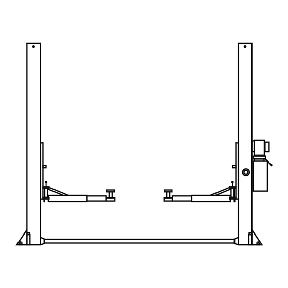
Page 9: Floor Plan
FLOOR PLAN MODEL TMG-TPL45 Lifting Capacity 10,000 lbs. / 4545 kg. A- Height Overall: 110” / 2805mm. B -Width Overall: 134" / 3400 mm. D- Floor Pan Height: 2" /50 mm F -Reach (Front Arm Min.): 31-1/2" / 800 mm. -
Page 10: Clearances
CLEARANCES 24”(610mm) Minimum to nearest wall 132” (3353mm) Minimum to nearest obstruction 14”(350mm) Minimum to nearest bay or obstruction 15” 104” 2640 156” (3963mm) Minimum to nearest obstruction LIFT HEIGHT CLEARANCE NOTE : there must be 70" plus the height of typical vehicle min distance from top of lift to nearest obstruction. - Page 11 2. Install a 1/4” NPT straight fitting into each cylinder Fig 3.2 port using Teflon tape then remove the cable sheaves located at the inside bottom of each post by first removing the hex head bolts, and then by removing the sheave pin. Remove cable Remove cable sheaves...
-
Page 12: Step 4 / Site Layout
STEP 4 (Site Layout) Determine which side of the lift will be the approach side. 2. Now decide where the power unit will be located. The POWER SIDE column has the power unit mounting bracket attached to the side. 3. Once a location is determined, use a carpenters chalk line to layout a grid for the post locations. Keep all dimensions square within 1/8”... -
Page 13: Step 6 / Installing Off Side Post
If shimming is required, insert the shims as necessary under the base plate so that when the anchor bolts are tightened, the posts will be plumb. (See Fig. 5.3) Fig 5.3 NOTE: Not include the shimming With the foot guards, shims and anchor bolts in place, tighten by securing the nut to the base then turning 3-5 full turns clockwise. -
Page 14: Step 8 / Installing Hydraulic Lines
The standard power unit for your lift is 220 volt, 60HZ, single phase. All wiring must be performed by a certified electrician only. SEE WIRING INSTRUCTIONS AFFIXED ALL WIRING MUST BE PERFORMED TO MOTOR FOR PROPER WIRING INSTRUCTIONS. BY A LICENSED ELECTRICIAN. DO NOT PERFORM ANY MAINTENANCE OR INSTALLATION OF ANY COMPONENTS WITHOUT FIRST ENSURING THAT ELECTRICAL POWER HAS BEEN DISCONNECTED AT THE SOURCE OR PANEL AND CANNOT BE RE-ENERGIZED UNTIL ALL MAINTENANCE AND/OR INSTALLATION PROCEDURES ARE COMPLETED. -
Page 15: Step 9 /Routing The Equalizer Cables
Route the power unit hose between the cylinder shaft Fig 8.2 and the equalizer sheave bracket. (See Fig 8.2) Cylinder Hose Straight Fitting WHEN ROUTING HYDRAULIC HOSES THROUGH THE POSTS, ROUTE HOSES THROUGH THE HOSE IS CLEAR OF ANY MOVING PARTS. - Page 16 With the carriages locked at 28” off the floor, route Fig 9.2 the threaded end of the equalizer cable across to the opposite side base plate sheave and up through the carriage. (See Fig. 9.2) From opposite base plate sheave NOTE: Post and carriage cut away for clarity Fig 9.3 Route the threaded end up and over the Top Plate...
- Page 17 WHEN THE CABLE ADJUSTING NUTS BOTTOM OUT ON THE THREADED END OF THE CABLE CONNECTOR AND THERE IS STILL SLACK IN THE CABLES, THE CABLES HAVE STRETCHED BEYOND THE SAFE USEFUL LENGTH AND NEED TO BE REPLACED WITH FACTORY APPROVEDCABLE ASSEMBLIES. DO NOT PLACE WASHERS, SPACERS OR OTHER DEVICES TO “SHORTEN”...
-
Page 18: Step 10 / Installing Floor Plate And Safety Cover
STEP 10 (Installing Floor Plate and Safety Cover) Fig 10.1 After safeties have been adjusted and checked for proper operation, install and tighten Power Side safety cover and Off Side safety cover mounting screws. (See Fig. 10.1) Screw Install the floor plate between the columns as shown. Fig 10.2 (See Fig. - Page 19 3. Each arm restraint gear can be oriented in a Left or Right configuration on the arms. Each arm and arm restraint gear must be positioned in the proper location in the lift head. (See Fig. 11.3 - 11.4) Fig 11.3 THE ARM RESTRAINT GEARS MUST BE POSITIONED AND ADJUSTED PROPERLY.
- Page 20 5. Verify the operation of the arm restraints by pulling Fig 11.6 up on the key ring of the arm restraint pin. Pivot the arms back and forth and test the operation of the arm restraint pin in various positions. (See Fig.
- Page 21 www.tmgindustrial.com 21/45 TOLL FREE:1-877-761-2819...
-
Page 22: Carriage Stop Bolt Installation Warning
CARRIAGE STOP BOLT INSTALLATION WARNING YOU MUST RE-INSTALL TOP CARRIAGE-STOP BOLT (SHOWN BELOW). TIGHTEN CARRIAGE-STOP BOLT TO 2-3 FT.-LBS. OF TORQUE UPON FINAL INSTALLATION INSPECTION. THESE INSTRUCTIONS MUST BE FOLLOWED TO ENSURE PROPER INSTALLATION AND OPERATION OF YOUR LIFT. FAILURE TO COMPLY WITH THESE INSTRUCTIONS CAN RESULT IN SERIOUS BODILY INJURY AND/OR DEATH AND/OR VOID PRODUCT WARRANTY. - Page 23 DO NOT PERFORM ANY MAINTENANCE OR INSTALLATION OF ANY COMPONENTS WITHOUT FIRST ENSURING THAT ELECTRICAL POWER HAS BEEN DISCONNECTED AT THE SOURCE OR PANEL AND CANNOT BE RE-ENERGIZED UNTIL ALL MAINTENANCE AND/OR INSTALLATION PROCEDURES ARE COMPLETED. IMPORTANT POWER UNIT INSTALLATION NOTES DO NOT run power unit without oil. Damage to pump can occur. ...
-
Page 24: Step 12 / Power Unit Connection
STEP 12 (Power Unit Connection) 1. Have a certified electrician run the power supply to motor. Refer to the data plate found on the motor for proper power supply and wire size. RISK OF EXPLOSION This equipment has internal arcing or parts that may spark and should not be exposed to flammable vapors. Motor should not be located in a recessed area or below floor level. -
Page 25: Post Installation Checklist
KEEP HANDS AND FEET CLEAR. Remove hands and feet from any moving parts. Keep feet clear of lift when lowering. Avoid pinch points. Check all MAIN SAFETY LOCKS to make sure they move freely and spring back to the lock position when released. Lubricate all SAFETY PIVOT points with light spray-oil. -
Page 26: Step 15 / Bleeding The Cylinders
STEP 15 (Bleeding the Cylinders) THE LIFT WILL MOVE DOWN WHEN BLEEDING MAKE SURE ALL EQUIPMENT, PERSONNEL, HANDS AND FEET ARE CLEAR BEFORE BLEEDING. After electrical power is connected and oil reservoir is full, press button to raise lift. Continue raising until lift cylinders fully extend to full height. DO NOT continue pressing button after lift reach-es full height. Damage to motor can occur if continued. - Page 27 LIFT OPERATION SAFETY DAILY inspect your lift. Never operate if it malfunctions or if it has broken or damaged parts. Use only qualified lift service personnel and genuine parts to make repairs. THOROUGHLY train all employees in use and care of lift, using ...
- Page 28 TO RAISE THE LIFT To avoid personal injury and/or property damage, permit only trained personnel to operate lift. After reviewing these instructions, practice using lift controls by running the lift through a few unloaded cycles before loading vehicle on lift. Always lift the vehicle using all four adapters.
- Page 29 Stop before making contact with vehicle. Check arm restraint TYPICAL LIFTING POINTS pins for engagement. If required, slightly move arm to allow restraint gear and pawl to mesh. DO NOT hammer arm restraint pin down as this will damage the restraint gear teeth. Raise vehicle until tires clear the floor.
- Page 30 WHILE USING LIFT Avoid excessive rocking of vehicle while on lift. Always use safety stands as needed or when removing or installing heavy components. TO LOWER THE LIFT When lowering the lift pay careful attention that all personnel and objects are kept clear. Always keep a visual line of site on the lift at all times.
- Page 31 Make sure vehicle is neither front nor rear heavy and select the proper configuration for the vehicle to be lifted (symmetric/asymmetric) as shown below. Center of balance should be midway between adapters. Symmetric Vehicle Loading TO RAISE LIFT Read operating and safety manuals before using lift. ...
- Page 32 REQUIRED MONTHLY MAINTENANCE Check all arm adjusting locks for proper operation. Check all cables connections, bolts and pins to ensure proper mounting and torque. Visually inspect safeties for proper operation. Lubricate posts with grease. Inspect all anchors bolts and re-tighten if necessary. ...
- Page 33 WIRE ROPE INSPECTION AND MAINTENANCE Lifting cables should be replaced every three - five years or when visible signs of damage are apparent. DO NOTUSE LIFT WITH DEFECTIVE / WORN CABLES. Lifting cables should be maintained in a well-lubricated condition at all times. Wire rope is only fully protected when each ...
- Page 34 Safety Labels www.tmgindustrial.com 34/45 TOLL FREE:1-877-761-2819...
- Page 35 Safe Lift Operation Automotive and truck lifts are critical to the operation and profitability of your business. The safe use of this and other lifts in your shop is critical in preventing employee injuries and damage to customer’s vehicles. By operating lifts safely you can ensure that your shop is profitable, productive and safe.
- Page 36 Some vehicle maintenance and repair activities may cause the vehicle to shift. Follow the manufacturer’s guidelines when performing these operations. The use of jack stands or alternate lift points may be required when completing some repairs. READ AND UNDERSTAND all safety warning procedures before operating lift. ...
-
Page 37: Troubleshooting Guide
LIFT WILL NOT RAISE POSSIBLE CAUSE Air in oil, Cylinder binding, Cylinder leaks internally, Motor run backward under pressure, Lowering valve leaks, Motor runs backwards, Pump damaged, Pump won’t prime, Relief valve leaks, 10. Voltage to motor incorrect, REMEDY INSTRUCTION Check for proper oil level. - Page 38 MOTOR WILL NOT RUN POSSIBLE CAUSE Fuse blown, Limit switch burned out, Micro switch burned out, Motor burned out, Voltage to motor incorrect, REMEDY INSTRUCTION Check for correct voltage ........Compare supply voltage with voltage on motor name tag.
- Page 39 WILL NOT RAISE LOADED LIFT POSSIBLE CAUSE Air in oil, Cylinder binding, Cylinder leaks internally, Lift overloaded, Lowering valve leaks, Motor runs backwards, Pump damaged, Pump won’t prime, Relief valve leaks, 10. Voltageto motor incorrect, REMEDY INSTRUCTION Check oil level ......... . The oil level should be up to the bleed screw in the reservoir with the lift all the way down.
- Page 40 LIFT WILL NOT STAY UP POSSIBLE CAUSE Air in oil, (1,2,3) Check valve leaks, (6) Cylinders leak internally, (7) Lowering valve leaks, (4,5,1,7,6) Leaking fittings, (8) REMEDY INSTRUCTION Check oil level ......... . The oil level should be up to the bleed screw in the reservoir with the lift all the way down.
-
Page 41: Part Number Lists
PARTS EXPLOSIN -(1) www.tmgindustrial.com 41/45 TOLL FREE:1-877-761-2819... - Page 42 PARTS EXPLOSIN -(2) www.tmgindustrial.com 42/45 TOLL FREE:1-877-761-2819...
- Page 43 PARTS EXPLOSIN -(3) www.tmgindustrial.com 43/45 TOLL FREE:1-877-761-2819...
- Page 44 PARTS EXPLOSIN -(4) www.tmgindustrial.com 44/45 TOLL FREE:1-877-761-2819...
- Page 45 Relieve lock slice Screw M6x10 Insurance mat tube Vitta connector M14x33 Insurance stop Power tubing 1/2”x1270 Spring pull plate Power unit TMG-ALP03 Lock slice weld Plain washer Ø30x2 Bolt M10x35 Power colum weld Plain washer Ø10 Hydraulic cylinders for power colum Spring washer Ø10...
Need help?
Do you have a question about the TMG-TPL45 and is the answer not in the manual?
Questions and answers