Table of Contents
Advertisement
Quick Links
PRODUCT MANUAL
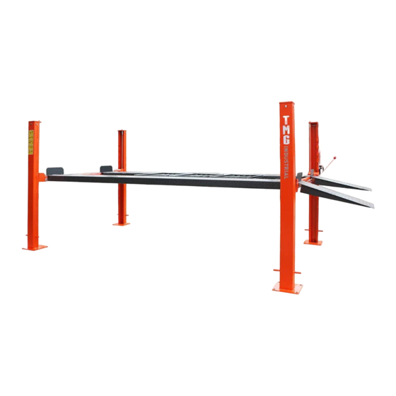
9,000 Ib Four Post Auto Lift
MODEL:TMG-ALF90
Please read the product manual completely before assembly
Check against the parts list to make sure all parts are received
Wear proper safety goggles or other protective gears while in assembly
Missing parts or questions on assembly?
Please call: 1-877-761-2819 or email: cs@tmgindustrial.com
Do not return the product to dealer, they are not equipped to handle your
requests
WWW.TMGINDUSTRIAL.COM
Toll Free:1-877-761-2819
Advertisement
Table of Contents

Related Manuals for TMG TMG-ALF90


Summary of Contents for TMG TMG-ALF90
- Page 1 PRODUCT MANUAL 9,000 Ib Four Post Auto Lift MODEL:TMG-ALF90 Please read the product manual completely before assembly Check against the parts list to make sure all parts are received Wear proper safety goggles or other protective gears while in assembly Missing parts or questions on assembly? Please call: 1-877-761-2819 or email: cs@tmgindustrial.com...
-
Page 2: Important Notice
OWNER’S RESPONSIBILITY IMPORTANT NOTICE To maintain the lift and user safety, the responsibility of the owner is to read and follow these instructions: Do not attempt to install this lift if you have never been trained on basic automotive lift installation procedures. Follow all installation and operation instructions. -
Page 3: Table Of Contents
TABLE OF CONTENTS Important Notice ..............................2 Owner’s Responsibility ............................2 Before You Begin ..............................2 Installer Operator/ Protective Equipment ......................4 Introduction/ Safety Warning Instructions......................5 Tools Required ............................... 6 Step 1 / Selecting Site ............................6 Step 2 / Floor Requirements / Concrete Specifications ..................6 Assembly View / Description of Parts ........................ -
Page 4: Installer Operator/ Protective Equipment
INSTALLER / OPERATOR PLEASE READ AND FULLY UNDERSTAND. BY PROCEEDING YOU AGREE TO THE FOLLOWING: Failure to follow danger, warning, and caution instructions may lead to serious personal injury or death to operator or bystander or damage to property. I have visually inspected the site where the lift is to be installed and verified the concrete to be in good condition and free of cracks or other defects. -
Page 5: Introduction/ Safety Warning Instructions
INTRODUCTION 2. Check the voltage, phase and proper amperage 1. Carefully remove the crating and packing materials. CAUTION! Be careful when cutting steel requirements for the motor shown on the motor plate. banding material as items may become loose and fall Wiring should be performed by a certified electrician only. -
Page 6: Tools Required
TOOLS REQUIRED Rotary Hammer Drill or Similar Medium Crescent & Pipe Wrenches 3/4” Masonry Bit Torque Wrench Hammer Crow Bar 4 Foot Level Chalk Line Open-End Wrench Set: SAE /Metric Medium Flat Screwdriver ... -
Page 7: Assembly View / Description Of Parts
When removing the lift from shipping angles pay close attention as the posts can slide and can cause injury. Prior to removing the bolts make sure the posts held securely by a fork lift or some other heavy lifting device. WW W . -
Page 8: Floor Plan / Specifications
Must Be Equal* *IMPORTANT NOTE* Check Diagonal Measurements To Ensure Square Layout Diagonal Measurements Must Be Equal. MODEL TMG-ALF90 Lifting Capacity 9,000 lbs / 4082 Kg. Max capacity / front axle 4,500 lbs. / 2,041 kg Max capacity / rear axle 4,500 lbs. -
Page 9: Clearances
CLEARANCES APPROACH B.Place target on floor at column positions (NOT 1. Lift Location: Use architects plan and Engineers on column base plates) and record readings. automatic level (transit) when available to locate lift. The above shows clearances of a typical bay layout. Lift C.Find the highest of the four locations. -
Page 10: Power Unit Location
POWER UNIT LOCATION IMPORTANT NOTE The Power Unit can be located at either “X” For the remainder of this instruction we will location shown below. It is important to locate illustrate the Power Unit mounted at the the POWERSIDE Runway (with Cylinder) on DRIVER-SIDE (LEFT) FRONT Column - TOP the SAME SIDE as the power unit location. -
Page 11: Step 3 / Column And Crosstube Installation
STEP 3 (Column & Crosstube Installation) 1. Place a chalk line on the floor according to the floor plan layout. Pay attention to the power Unit location. Locate and stand the columns at their respective locations. DO NOT BOLT Columns down at this time. Use caution to prevent the Columns from falling over. -
Page 12: Step 5 / Powersiderunway Installation
Manually raise the Crosstubes until the Primary Safety Locks engage and rest on the third or fourth lock position or approximately 24” off the ground. (See Fig 5.1 Powerside Runway Fig 4.1) Offside Runway 2. Install Cylinder and Cable Block as shown. (See Fig. -
Page 13: Step 6 / Offside Runway Installation
STEP 7 Fig 5.4 (Safety Lock Release Installation) 1. Install unlocked handles on the Crosstubes (power unit mounting side) and install joint bearings with M6x25, Install long, short unlock rod with M6X35.(See Fig7.1) Fig 7.1 STEP 6 2. Install long unlocking lever on the Crosstubes and install joint bearings with M6x25,Install long, short unlock rod with (Offside Runway Installation) M6X35.(See Fig7.2) -
Page 14: Cable Routing
WW W . T M G I N D U ST R I A L . C O M P 14 / 33 To l l Fr e e : 1 - 8 7 7 - 7 6 1 - 2 8 1 9... -
Page 15: Step 8 /Cable Sheave Installation
STEP 8 (Cable / Sheave Installation) 1. Inspect Cables to ensure proper lengths. All Cables should have ID tags showing proper Cable lengths. Failure to route Lifting Cables as described may lead to serious personal injury and/or death to operator or bystander and/or may cause damage to property. -
Page 16: Step 10 / Power Unit Installation
STEP 10 (Power Unit Installation) Fig 9.3 Mount the Power Unit to the Mounting Bracket using the M8 Hex Head Bolts and Nylock Nuts then fill the reservoir with 12 quarts of 10-WT hydraulic oil or Dexron III automatic transmission fluid. (See Fig. 10.1) M8 Nylock Nuts Flat... -
Page 17: Step 11 / Routing Hydraulic Hoses
The standard Power Unit for your lift is 220 volt, 60HZ, single phase. All wiring must be performed by a certified electrician only. SEE WIRING INSTRUCTIONS AFFIXED TO MOTOR FOR PROPER WIRING INSTRUCTIONS. DO NOT run Power Unit with no oil. Damage to pump can occur. The Power Unit must be kept dry. - Page 18 DO NOT PERFORM ANY MAINTENANCE OR INSTALLATION OF ANY COMPONENTS WITHOUT FIRST ENSURING THAT ELECTRICAL POWER HAS BEEN DISCONNECTED AT THE SOURCE OR PANEL AND CANNOT BE RE-ENERGIZED UNTIL ALL MAINTENANCE AND/OR INSTALLATION PROCEDURES ARE COMPLETED. IMPORTANT POWER-UNIT INSTALLATION NOTES ...
-
Page 19: Step 12 / Power Unit Hook Up
STEP 12 STEP 13 (Power Unit Hook Up) (Lift Start Up / Final Adjustments) 1. Have a certified electrician run the power supply to 1. Make sure the Power Unit reservoir is full with 12 motor. Refer to the data plate found on the motor for quarts of 10-WT hydraulic oil or Dexron-III automatic proper power supply and wire size. -
Page 20: Step 14 / Anchoring The Columns
Using the Base plate on each Column as a guide, NOTE: drill each anchor hole approximately 4-1/2” deep using There will be initial stretching of the cables in the a rotary hammer drill and 3/4” concrete bit. beginning and/or with increased loads. Adjust the (See Fig. -
Page 21: Step 15 / Attaching Approach Ramps/Tire Stops
Using an engineer’s automatic Level (transit), locate 6. After any necessary shims are installed, tighten each the Level, at a convenient location in the shop that allows nut 3-5 turns past hand tight. IMPORTANT - If anchor an unobstructed view of all four corners of the runways. bolts do not hold when tightened to indicated amount, concrete must replaced. -
Page 22: Step 17 / Bleeding
STEP 17 • THOROUGHLY train all employees in use and care of (Bleeding) lift, using manufacturer’s instructions and “Lifting It Right” and “Safety Tips” supplied with the lift. 1. Lift must be fully lowered before changing or adding fluid. • NEVER allow unauthorized or untrained persons to position vehicle or operate lift. - Page 23 4. Raise the lift to the desired height by pressing the push button on the power unit. 5. After vehicle is raised to the desired height, lower the lift onto the nearest Safety Lock. Do not allow IF YOU ARE NOT COMPLETELY FAMILIAR WITH Cables to become slack.
- Page 24 WIRE ROPE INSPECTION AND MAINTENANCE Lifting cables should be replaced every three - five years or when visible signs of damage are apparent. DO NOT USE LIFT WITH DEFECTIVE / WORN CABLES. Lifting cables should be maintained in a well-lubricated condition at all times. Wire rope is only fully protected when ...
- Page 25 Safe Lift Operation Automotive and truck lifts are critical to the operation and profitability of your business. The safe use of this and other lifts in your shop is critical in preventing employee injuries and damage to customer’s vehicles. By operating lifts safely you can ensure that your shop is profitable, productive and safe.
- Page 26 DO NOT leave the controls while the lift is still in motion. DO NOT stand directly in front of the vehicle or in the bay when vehicle is being loaded or driven into position. DO NOT Go near vehicle or attempt to work on the vehicle when being raised or lowered. ...
-
Page 27: Troubleshooting Guide
TROUBLESHOOTING GUIDE 1. LIFT WILL NOT RAISE POSSIBLE CAUSE 1. Air in oil, (1,2,8,13) 2. Cylinder binding, (9) 3. Cylinder leaks internally, (9) 4. Motor run backward under pressure, (11) 5. Lowering valve leaks, (3,4,6,10,11) 6. Motor runs backwards, (7,14,11) 7. - Page 28 2. MOTOR WILL NOT RUN POSSIBLE CAUSE Fuse blown, (5,2,1,3,4) Limit switch burned out, (1,2,3,4) Microswitch burned out, (1,2,3,4) Motor burned out, (1,2,3,4,6) Voltage to motor incorrect, (2,1,8) REMEDY INSTRUCTION Check for correct voltage ............. Compare supply voltage with voltage on motor name tag.
- Page 29 4. WILL NOT RAISE LOADED LIFT POSSIBLE CAUSE 1. Air in oil, (1,2,3,4) 2. Cylinder binding, (5) 3. Cylinder leaks internally, (5) 4. Lift overloaded, (6,5) 5. Lowering valve leaks, (7,8,1,5,9) 6. Motor runs backwards, (10,12,9) 7. Pump damaged, (5,9) 8.
- Page 30 5. LIFT WILL NOT STAY UP POSSIBLE CAUSE 1. Air in oil, (1,2,3) 2. Check valve leaks, (6) 3. Cylinders leak internally, (7) 4. Lowering valve leaks, (4,5,1,7,6) 5. Leaking fittings, (8) REMEDY INSTRUCTION 1. Check oil level ..................The oil level should be up to the dip stick in the reservoir with the lift all the way down.
-
Page 31: Parts Drawings
PARTS DRAWING WW W . T M G I N D U ST R I A L . C O M P 31 / 33 To l l Fr e e : 1 - 8 7 7 - 7 6 1 - 2 8 1 9... - Page 32 Parts List Index# Description Index# Description Powerside Column Cylinder 27X85x2060 Top Plate Cylinder Pin Vice Column Front Block Powerside Runway Rear Block Offside Runway Traction Board Hanging Board Main Column Traction Board Crosstube Unlock Handle Shield Connecting Sleeve Joint Bearing Long Unlocking Lever Fixing Sleeve Short Unlocking Rod...
- Page 33 Product Dimension Drawing WW W . T M G I N D U ST R I A L . C O M P 33 / 33 To l l Fr e e : 1 - 8 7 7 - 7 6 1 - 2 8 1 9...
Need help?
Do you have a question about the TMG-ALF90 and is the answer not in the manual?
Questions and answers