
Related Manuals for Marvel MLCP215-IS01B


Summary of Contents for Marvel MLCP215-IS01B
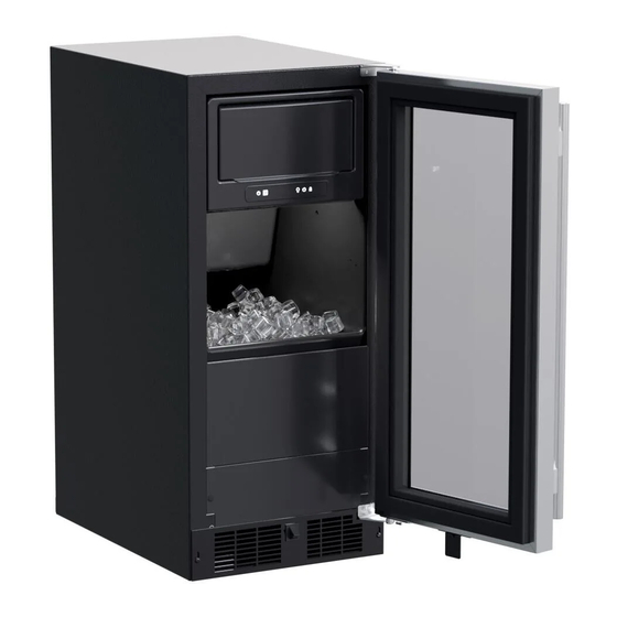
- Page 1 OWNER’S GUIDE & SERVICE MANUAL M A R V E L U N D E R C O U N T E R R E F R I G E R AT I O N Model: MLCP215-IS01B...
- Page 2 • Tech Support: techsupport@marvelrefrigeration.com Got a Marvelous Design? We would love to see how your Marvel product looks in its new home. You can send us photos of your installed product at marketing@marvelrefrigeration.com, and we might feature your Marvel home design on our website and...
-
Page 3: Table Of Contents
TABLE OF CONTENTS Tip: Click on any section below to jump directly there Safety Compressor Specifications Important Safety Instructions Control Operation - Service Thermistor Installation Warranty Unpacking Your Appliance Electrical Cutout & Product Dimensions Side-by-Side & Stacking Installations Door Reversal Integrated Panel Dimensions Integrated Panel Installation Installing The Water Supply... - Page 4 IMPORTANT SAFETY INSTRUCTIONS Important Safety Instructions Warnings and safety instructions appearing in this guide are not meant to cover all possible conditions and situations that may occur. Common sense, caution and care must be exercised when installing, maintaining or operating this appliance. Recognize Safety Symbols, Words and Labels WARNING...
- Page 5 UNPACKING YOUR APPLIANCE WARNING CAUTION If the appliance was shipped, handled or stored in other EXCESSIVE WEIGHT HAZARD than an upright position for any period of time, allow the Use two or more people to move product. appliance to sit upright for a period of at least 24 hours Failure to do so can result in personal injury.
- Page 6 ELECTRICAL Electrical Connection A grounded 115 volt, 15 amp dedicated circuit is required. This product is factory equipped with a power supply cord that has a three-pronged, grounded plug. It must be Do not remove plugged into a mating grounding type receptacle in ground prong accordance with the National Electrical Code and applicable local codes and ordinances.
-
Page 7: Cutout & Product Dimensions
CUTOUT AND PRODUCT DIMENSIONS ROUGH-IN OPENING DIMENSIONS CABINET DIMENSIONS "A" "B" "C" "D" "E" "F" "G" "H" "J" 15" 34” to 35" 24" 14 7/8" 33 3/4” to 34 3/4”" 22 7/8" 37 3/8" (8.1 cm) (85.7 cm to 88.3 cm) (61 cm) (37.8 cm) (86.4 cm to 88.9 cm) - Page 8 CUTOUT AND PRODUCT DIMENSIONS PRODUCT DATA ELECTRICAL PRODUCT REQUIREMENTS # WEIGHT 105 lbs 115V/60Hz/15A (47.6 kg) "J" "H" "D" "G" "E" " (54.6 cm) "F" Glass Door Shown Minimum rough-in opening required is to be larger than the adjusted height of the cabinet. A grounded 15 amp dedicated circuit is required.
-
Page 9: Side-By-Side & Stacking Installations
SIDE-BY-SIDE AND STACKING INSTALLATIONS Side-by-Side Installation Other Site Requirements Stainless steel models which include the standard stainless Units must operate from separate, properly grounded elec- handle will require 4-9/16" (116 mm) to allow both doors to trical receptacles placed according to each unit's electrical open to 90°... -
Page 10: Door Reversal
DOOR REVERSAL Door Reversing Instructions Tools Needed: • 1/8” Hex Key • 5/32” Hex Key • Phillips Screwdriver Open door and remove Hinge Pin from the Upper Hinge using a 1/8” Hex Key tool making sure to steady the Using a Phillips Screwdriver, remove the 6 screws from both the Upper and Lower Hinges and save for later steps Once the Hinges are removed from the unit, using a Phillips Screwdriver, remove the Bushing Screw and Hinge Pin Screw and save for later steps On the Bottom Hinge, reattach the Bushing Screw and Hinge Pin Screw to the opposite side... - Page 11 DOOR REVERSAL 6. Remove the door switch actuator tab from the door and attach it to the opposite side Door switch actuator tab 7. Reattach the Upper and Lower Hinges, and Hinge Brackets to opposite sides. Then install the door.
-
Page 12: Integrated Panel Dimensions
INTEGRATED PANEL DIMENSIONS NOTE 15" (38.1 cm) wide appliance Back of 7/16" (1.1cm) Panel Front of 5/16" Panel (0.8cm) ⁄ " (2.9 cm) Front of 5/16" Panel (0.8cm) Back of 7/16" Panel (1.1cm) 15" (38.1 cm) Door Dimensions... -
Page 13: Integrated Panel Installation
INTEGRATED PANEL INSTALLATION 5/8" (1.6 cm) or 3/4" (1.9 cm) panel 14 5/8 (37.1 cm) width 29 21/32" (75.3 cm) height NOTE NOTE NOTE... - Page 14 USING YOUR ELECTRONIC CONTROL Electronic Control Control Function Guide Function Command Notes ON/OFF Press and release. Unit will immediately turn ON or OFF. Toggle Interior Light - Door Press and release to toggle interior light oper- Light output 50%. Closed ation.
-
Page 15: Installing The Water Supply
INSTALLING THE WATER SUPPLY Water Supply CAUTION Observe and follow all local building codes when installing this appliance. This ice machine must be connected to a potable cold water supply line. delivering water pressure between a minimum of 20 psi and a maximum of 120 psi. Use 1/4"... -
Page 16: Ice Maker Operation
ICE MAKER OPERATION The Ice Making Process sheet is released and slides onto the grid cutter cutter’s heated fractional freezing to form a slab of ice that is clear and wires. The water containing the dissolved minerals is has less dissolved solids than the water it is produced drained after each freezing cycle. - Page 17 ICE MAKER OPERATION Ice Production The ice machine will keep producing ice until the ice machine’s bin is full and will restart automatically when In normal mode the ice machine will produce up to 39 ice needs to be replenished in the bin. The ice bin is pounds (17.7 kg) of clear ice in a 24-hour period when installed in a 72°F ambient with a 55°F water supply.
- Page 18 "nickel safe" ice maker cleaner. You can order ice machine plate and grid cutter cleaner (part # S41013789) at marvelrefrigeration.com. area that is not embedded in wires CAUTION Use only Marvel-approved ice machine cleaner and follow all label warnings and directions. Incorrect chemical warranty.
- Page 19 CARE AND CLEANING Remove ice from bin. Pull plug from the reservoir. Once reservoir is empty, replace plug. Hold the button for 10 seconds to show "CL" on the display. Lift Fascia door to access evaporator plate. Lift or remove splash shield to expose evaporator plate.
- Page 21 LONG TERM STORAGE AND WINTERIZATION water in the ice-making system. CAUTION This ice machine must have all water drained and removed to prevent ice machine damage as well as possible water damage to the surrounding area in freezing conditions. These damages are not covered under warranty. CAUTION Do not use any type of anti-freeze or other solution as a substitution for properly draining the ice machine.
- Page 22 LONG TERM STORAGE AND WINTERIZATION 7. Disconnect the water valve’s outlet water line to the Reconnect the water valve outlet water line. reservoir and drain the remaining water left in the water Reinstall the ice machine’s access cover. line trap area. Clean and dry the ice machine’s storage bin.
- Page 23 LONG TERM STORAGE AND WINTERIZATION To Restart the Ice Machine access for the air hose. Reconnect or turn on the water supply line. Apply air pressure (approximately 10 psi) to the end of Reconnect drain tubing if removed. the vent tube which will purge the remainder of the Plug in the power cord to a wall outlet and turn the water from the drain pump and the drain line.
-
Page 24: Obtaining Service
OBTAINING SERVICE If Service is Required: • If the product is within the first year warranty period please contact your dealer or call Marvel Customer Service at 616.754.5601 for directions on how to obtain warranty coverage in your area. •... -
Page 25: Troubleshooting
TROUBLESHOOTING Before You Call for Service WARNING troubleshooting guide below. Locate the problem in the Electrocution Hazard guide and refer to the cause and its remedy before calling • Never attempt to repair or perform maintenance on for service. The problem may be something very simple the appliance until the main electrical power has been disconnected. - Page 26 TROUBLESHOOTING Ice Quality Troubleshooting the Drain Pump Is there mineral scale build up on the evaporator NOTE plate If the drain pump reservoir (not the ice machine bin) Is there a high mineral content in the water? The water If the ice machine is not working, check the following: Are food items being stored in the ice bin? Remove •...
- Page 27 SERVICE CORD GROUND GREEN GREEN PUMP SWITCH N.O. POWER GROUND PUMP Interior LED Condenser Fan TRANSFORMER HIGH WATER LIMIT BLACK SWITCH N.C. OUTLET Interior LED Pro Model GREEN DRAIN PUMP (OPTIONAL) SERVICE CORD- DRAIN PUMP GROUND Fresh Food Thermistor HOT GAS VALVE Evap Thermistor B/Y B/Y Door Switch...
-
Page 28: Product Liability
The part that caused the damage must be returned to Marvel in its entirety. The part must be clearly labeled with the serial number of the unit it was removed from, the date, and the servicer who removed the part. -
Page 29: Warranty Claims
Claims must be submitted online at • Final billing - Remodel www. marvelservice . co m Warranty parts will be shipped at no charge after Marvel • 60 day submittal d eadline from date of completed confirms warranty status. Please provide the model, serial service number, part number and part d escription. - Page 30 MAIN CONTROL BOARD KIT 90-54002-54 GRILLE S41015692-BLK LED STRIP WHITE S68100 BLACK ROCKER LIGHT SWITCH 42246922 THERMISTOR ASSEMBLY S68092 UI DISPLAY KIT-MARVEL S68167-01 CONDENSER FAN MOTOR 42248161 CONDENSER FAN BLADE 42248160 10 CONDENSER SENSOR 90-54013-00 11 COMPRESSOR ASSEMBLY 90-54006-00 12 INVERTER-COMPRESSOR...
-
Page 31: Ordering Replacement Parts
Warranty parts will be shipped at no charge after Marvel confirms warranty status. Please provide the model, serial number, part number and part description. Some parts will require color or voltage information. -
Page 32: R600A Specifications
PERSONNEL DO HOT PUNCTURE REFRIGERANT TUBING refrigeration system. RISK Of FIRE OR EXPLOSION. FIAMHA_ B LE REFRIGERANT USED. CONSULT Never substitute Marvel OEM replacement parts REPAIR IIANUAVOWHER'S GUIDE BEFORE ATTEMPTING TO SERVICE THIS PRODUCT. ALL SAFETY PRECAUTIONS HUST BE FOUOWEO. - Page 33 R-600A SPECIFICATIONS/LABELING WARNING R-600a equipped products are labeled (both the unit and the compressor). Only skilled and well trained service technicians permitted to service R-600a equipped products. R-600a is colorless and odorless. All tools and equipment must be approved for use with R-600a refrigerant.
- Page 34 Evacuate/reclaim via the piecing pliers to ensure the When re-brazing, the system must be purged with dry system is empty of R-600a before any system work is nitrogen and at least one access point open to the performed. atmosphere. When re-brazing, proper ventilation is required along with constant monitoring for the presence of R600a refrigerant.
- Page 35 The low side of the refrigeration system (evaporator, Proper ventilation during service is required. compressor and suction line) must be leak tested with the compressor off (equalized pressure). Never apply a torch to a charged R-600a refrigeration system. RECHARGING No air is ever to be allowed inside the refrigeration system Use OEM replacement service parts and do not alter the (R-600a refrigerant or dry nitrogen only).
-
Page 36: System Diagnosis Guide
System Diagnosis Guide REGRIGERATION SYSTEM DIAGNOSIS GUIDE System Suction Suction Compressor Condenser Capillary Evaporator Wattage Condition Pressure Line Discharge Tube Normal Normal Slightly Very hot Very hot Warm Cold Normal below room temperature Overcharge Higher than Very cold Slightly warm Hot to warm Cool Cold... - Page 37 Compressor Specifications FMXA9C REFRIGERANT R600A DANGER VOLTAGE 115 VAC FREQUENCY 60 Hz 5 Ohm at 77 START WINDING ° Electrocution can cause death or serious injury. RUN WINDING 7 Ohm at 77 ° Burns from hot or cold surfaces can cause serious 12 Ohm at 77 °...
- Page 38 Control Operation-Service CONTROL FUNCTION GUIDE FUNCTION COMMAND DISPLAY/ OPTIONS UI BUTTON LAYOUT Unit will immediately Press � and release ON/OFF turn ON or OFF Sabbath Mode See "Sabbath Mode" section Hidden Button SHOWROOM MODE -Access Service Menu This mode is designed to show units in a display -No LED directly above.
- Page 39 Thermistors Evaporator Thermistor Thermistors are used for various temperature readings. Thermistors provid e If the evaporator thermistor fails, the unit will rely on a reliable temperature readings preset defrost timer during defrost cycles. The unit will using a resistance which varies based on surrounding temperatures. If a otherwise operate normally.
- Page 40 For designated Marvel Professional product, Marvel offers a one year extension of the two year warranty coverage from the date of purchase, free of charge. To take advantage of this third year warranty, you must register your product with Marvel within 60 days from the date of purchase at marvelrefrigeration.com and provide proof of purchase.
- Page 41 Marvel Refrigeration 1260 E. Van Deinse St. Greenville MI 48838 616.754.5601 All specifications and product designs subject to change without notice. Such revisions do not entitle the buyer to corresponding changes, improvements, additions, replacements or compensation for previously purchased products.
Need help?
Do you have a question about the MLCP215-IS01B and is the answer not in the manual?
Questions and answers