
Related Manuals for Redarc EBRH-ACCV3-NA


Summary of Contents for Redarc EBRH-ACCV3-NA
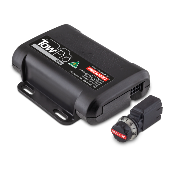
- Page 1 Tow‑Pro Elite ® Electric Trailer Brake Controller 12 V or 24 V, 1 to 3 Axles MODEL: EBRH‑ACCV3‑NA ƒ...
- Page 2 Tow‑Pro® Elite Electric Trailer Brake Controller (EBRH‑ACCV3‑NA) The Tow‑Pro Elite is an electric trailer brake ® controller designed to suit most common trailer braking applications. It requires minimal dash space and is simple to install and operate. The Tow‑Pro Elite has selectable Proportional or ®...
-
Page 3: Table Of Contents
CONTENTS WARNINGS AND SAFETY INSTRUCTIONS ��������������������������������������������������������������������������� 1 SPECIFICATIONS ����������������������������������������������������������������������������������������������������������������� 1.1 Kit Contents ����������������������������������������������������������������������������������������������������������������� 1.2 Dimensions and Connection �������������������������������������������������������������������������������������� 2 INSTALLATION ��������������������������������������������������������������������������������������������������������������������� 2.1 Mounting the main unit ����������������������������������������������������������������������������������������������� 2.2 Wiring the brake controller ���������������������������������������������������������������������������������������� 2.3 Mounting the Remote Head ������������������������������������������������������������������������������������� 2.4 Active Calibration �������������������������������������������������������������������������������������������������������... -
Page 4: Warnings And Safety Instructions
Elite Electric Trailer Brake Controller. ® Do not operate the controller unless you have read and understood this manual and the controller is installed as per these installation instructions. REDARC recommends that the charger be installed by a suitably qualified person. SAFETY MESSAGE CONVENTIONS... - Page 5 8. During the calibration step of the Tow‑Pro Elite, braking of the trailer may be inconsistent. ® REDARC recommends calibrating the Tow‑Pro Elite without a trailer attached. A normal ® drive of a few miles will do for this purpose. If calibrating with a trailer attached, then the recommended dial setting for the Tow‑Pro...
-
Page 6: Specifications
1 SPECIFICATIONS Part Number EBRH‑ACCV3‑NA Operating Voltage 9 V to 32 V Nominal Input System Voltage 12 V 24 V OFF: 0 V OFF: 0 V Brake Input Signal Voltage ON: +12 V nominal ON: +24 V nominal Brake Coil Voltage 12 V Max. Trailer Axles 3 Axles Nominal Current Draw 18 A Max. -
Page 7: Kit Contents
1.1 Kit Contents Reference Description Remote Head Assembly Main Unit Remote Head Nut Remote Head Knob Remote Head Bezel Remote Head Cable 3'3" (1 m) Main Unit Wires and Connector 1'7" (0.5 m) Tow‑Pro Universal Switch Insert Panel Specifications | 7... -
Page 8: Dimensions And Connection
1.2 Dimensions and Connection 1.18" (30.0 mm) 0.39" (10.0 mm) 0.39" (10.0 mm) Remote Head Connection 3.94" (100.0 mm) Brake Input Output 4.09" (104.0 mm) Power (BLUE) (BLACK) Brake Ground/ Lights Earth (RED) (WHITE) 0.45" (11.5 mm) 0.77" 1.25" 0.79" (19.6 mm) 0.58"... -
Page 9: Installation
2 INSTALLATION 2.1 Mounting the main unit The Tow‑Pro Elite should be mounted inside the vehicle cabin using either ⁄ " (M4) diameter ® screws or other secure fitting methods at the mounting points provided. It is essential to mount the unit in a location which allows access to the intended remote head location. -
Page 10: Wiring The Brake Controller
REDARC Electronics manufactures a number of vehicle‑specific wiring harnesses for quick and easy installation (refer to REDARC’s website for details). The universal wiring harness included with the EBRH‑ACCV3‑NA kit is the TPH‑025 ‘Universal Harness’ which is typically used for older vehicles not covered by our range of wiring harnesses. - Page 11 2.2.2 WIRING — ELECTRIC BRAKES For 12 V and 24 V vehicle electrical systems, the Tow‑Pro Elite is designed to operate electric ® brakes without the need for any additional converters. For wire selection refer to the wiring gauge guide "Wiring Gauge Guide" on page 25 A Fuse or 30 A Circuit Breaker 12 AWG...
- Page 12 2.2.3 WIRING — ELECTRIC/HYDRAULIC BRAKES NOTICE Always refer to the manufacturer’s specifications for your Electric/Hydraulic Braking system prior to installation and usage of the Tow‑Pro Elite. ® 12 V VEHICLE SYSTEMS The Tow‑Pro Elite is designed to operate both Electric trailer brake systems and 12 V ®...
- Page 13 Many modern vehicles use a CAN Bus system for signalling when to apply the vehicles brakes as required by safety systems including adaptive cruise control, stability control, Autonomous Emergency Braking (AEB) and hill descent control. For these vehicles, REDARC recommend the following wiring configuration.
-
Page 14: Mounting The Remote Head
2.3.1 INSTALLATION ACCESSORIES REDARC offer a range of vehicle specific switch inserts and vehicle specific wiring kits designed to make the installation of the Tow‑Pro Elite easier. The range includes most popular SUV and LCV’s and is frequently being updated and added to. A full listing of Switch Inserts and Wiring Kits is available for purchase on the REDARC website. - Page 15 2.3.3 MOUNTING THE REMOTE HEAD ON A DASH OR CONSOLE PANEL Ensure that there is enough space behind the mounting location to fit the Tow‑Pro control head and remote head cable before drilling any holes. 1/16" – 9/64" (1.25 – 3.6 mm) 25/64"...
-
Page 16: Active Calibration
2.4 Active Calibration When the unit is first powered, Active Calibration must first become confident in the vehicle direction of travel. Until this time the LED will flash Blue/Green. During Calibration Once Calibrated Time Time Active Calibration constantly monitors the vehicle’s direction of travel and allows the Tow‑Pro Elite ®... -
Page 17: Operation
3 OPERATION 3.1 Adjusting the Braking Force In both modes the braking level can be adjusted to suit varying trailer loads, braking requirements or user comfort by adjusting the control knob on the remote head. The lower end of the scale (below level 5) should be used as a starting point and adjusted accordingly once braking requirements are established. -
Page 18: Operating Modes
3.3 Operating Modes The Tow‑Pro Elite offers two modes of operation — Proportional and User Controlled. On the ® first application of power to the black wire, the Tow‑Pro Elite will start‑up in Proportional mode. ® Every time a trailer is connected, the Tow‑Pro Elite will start up in the mode that was last selected ®... - Page 19 3.3.3 CHANGING MODES Changing modes can only be completed with a trailer connected. Ensure the vehicle has come to a complete stop before beginning the mode change process. Changing between modes requires the user to complete the following process: Rotate the knob fully counter‑clockwise. Apply Vehicle Brakes.
-
Page 20: Park Brake Feature
3.4 Park Brake Feature If the Tow‑Pro Elite detects that the vehicle brakes are applied for longer than 3 seconds whilst ® the vehicle is stationary, it will apply the trailer brakes in an intelligent manner to reduce the required braking effort whilst decreasing the risk of rolling forward or backward whilst stopped. -
Page 21: Led Indication
3.6 LED Indication The Tow‑Pro Elite will indicate both Mode and Fault Condition through color and flash sequences ® of the LED indicator. The table shows how the Tow‑Pro Elite will indicate Operation of the unit. ® NOTE: LEDs will glow full brightness when gain control is adjusted or manual override is pressed. After release of the gain control knob the LED brightness will reduce. -
Page 22: Troubleshooting
There is a fault with the connection. Please contact flashes PURPLE twice unit and/or the installation REDARC or visit your local auto‑ electrician for further assistance Check all wiring from the unit to the The LED is YELLOW and There is a short circuit... - Page 23 LED Sequence Symptom/Description Possible Cause Suggested Action The unit has detected an internal fault of your Check for faults according to the Al‑Ko iQ7 hydraulic/ manual for the Al‑Ko iQ7 actuator 1 Second pneumatic system The LED is flashing RED There is a voltage drop If you don’t have an Al‑Ko iQ7, between the trailer...
-
Page 24: Periodic Maintenance And Checks
It is important to have a qualified technician check the function of your trailer system on a periodic basis to ensure that everything is operating correctly. REDARC recommend that you visit a qualified technician before the beginning of each holiday season to ensure that any towing aids or systems are working correctly. -
Page 25: Frequently Asked Questions
Can the remote head cable be extended? No, the remote head cable is not a standard cable and REDARC recommend not to cut and extend the supplied cable. REDARC have a range of non‑standard cable lengths available on our website. -
Page 26: Fcc Declaration
6 FCC DECLARATION This device complies with part 15 of the FCC Rules. Operation is subject to the following two conditions: (1) This device may not cause harmful interference, and (2) this device must accept any interference received, including interference that may cause undesired operation Note: This equipment has been tested and found to comply with the limits for a Class B digital device, pursuant to part 15 of the FCC Rules. -
Page 27: Warranty
YEAR and MONTH of manufacture, in the format YYMM. Design and specifications are subject to change without notice� | Copyright © REDARC Electronics Pty Ltd� All rights reserved� REDARC®, THE POWER OF REDARC®, and Tow-Pro® are trademarks of REDARC Electronics Pty Ltd�... - Page 28 CONTACT Tech Support 1300 REDARC (1300‑733‑272) Australia +61 8 8322 4848 New Zealand +64 9 222 1024 UK & Europe +44 (0)20 3930 8109 redarc.com.au +1 (704) 247‑5150 Canada +1 (604) 260‑5512 Mexico +52 (558) 526‑2898 redarcelectronics.com INST72-2 EN...
Need help?
Do you have a question about the EBRH-ACCV3-NA and is the answer not in the manual?
Questions and answers