Redarc TOW-PRO ELITE Manual
Electric trailer brake controller 12 or 24volt, 1 to 3 axles
Hide thumbs
Also See for TOW-PRO ELITE:
- Manual (28 pages) ,
- Instruction manual (28 pages) ,
- Manual (24 pages)
Table of Contents
Advertisement
Advertisement
Table of Contents

Related Manuals for Redarc TOW-PRO ELITE


Summary of Contents for Redarc TOW-PRO ELITE
- Page 1 Elite Electric Trailer Brake Controller 12 or 24Volt, 1 to 3 Axles...
- Page 2 TOW-PRO ELITE (EBRH-ACCV3-NA) TRAILER BRAKE CONTROLLER ® ® The Tow-Pro Elite is an electric trailer brake controller designed to suit most common trailer braking applications whilst requiring minimal dash space and being simple to install and operate. ® The Tow-Pro Elite offers selectable Proportional or User Controlled trailer braking modes allowing the user to choose the braking style depending on the road or terrain conditions, vehicle type, or driver preference.
- Page 3 During the calibration step of the Tow-Pro Elite, braking of the trailer may be inconsistent. ® REDARC recommends calibrating the Tow-Pro Elite without a trailer attached. A normal drive of ® a few miles will do for this purpose. If calibrating with a trailer attached, then the recommended dial setting for the Tow-Pro Elite is 4 or less.
-
Page 4: Table Of Contents
CONTENTS Table of Contents Page 1 - Specifications 2 - Installation 2.1 - Mounting the main unit 2.2 - Wiring the brake controller 2.2.1 Red Wire (Vehicle Brake light) Connection 2.2.2 Wiring Diagrams - Electric Brakes 2.2.3 Wiring Diagrams - Electric / Hydraulic Brakes 2.2.4 Wiring Diagrams - Vehicles with CAN Bus System 2.3 - Mounting the Remote Head 2.4 - Installation Accessories... - Page 5 SPECIFICATIONS Kit Contents 1. Remote Head Assembly 2. Main Unit 3. Remote Head Nut 4. Remote Head Knob 5. Remote Head Bezel 6. Remote Head Cable 3’3” (1m) 7. Main Unit Wires & Connector 1’7” (0.5m) 8. Tow-Pro universal switch insert panel Dimensions &...
-
Page 6: Installation
INSTALLATION Mounting the main unit ® The Tow-Pro Elite should be mounted inside the vehicle cabin using either 5/32” (M4) diameter screws or other secure fitting methods at the mounting points provided. It is essential to mount the unit in a location which allows access to the intended remote head location. -
Page 7: Wiring The Brake Controller
Wiring the brake controller REDARC Electronics manufactures a number of vehicle-specific wiring harnesses for quick and easy installation (refer to REDARC’s website for details). The universal wiring harness included with th EBRH-ACCV3-NA kit is the TPH- 025 ‘Universal Harness’ which is typically used for older vehicles not covered by our range of wiring harnesses. -
Page 8: Red Wire (Vehicle Brake Light) Connection
INSTALLATION 2.2.1 Red Wire (Vehicle Brake light) Connection The requirements for a suitable connection of a brake controller trigger wire are quite specific. This connection point must: • Provide a voltage of the same voltage level as the “Start Battery*” while the vehicle brakes are applied. -
Page 9: Wiring Diagrams - Electric Brakes
INSTALLATION 2.2.2 Wiring Diagrams - Electric Brakes ® For 12V and 24V vehicle electrical systems, the Tow-Pro Elite is designed to operate electric brakes without the need for any additional converters. For wire selection refer to the wiring gauge guide in Section 6. 25A Fuse or 30A Circuit Breaker (CBK30-EB) -
Page 10: Wiring Diagrams - Electric / Hydraulic Brakes
INSTALLATION 2.2.3 Wiring Diagrams - Electric / Hydraulic Brakes Always refer to the manufacturer’s specifications for your Electric/Hydraulic ® Braking system prior to installation and usage of the Tow-Pro Elite. 12V Vehicle Systems ® The Tow-Pro Elite is designed to operate both Electric trailer brake systems and 12V Electric / Hydraulic trailer brake systems. -
Page 11: Wiring Diagrams - Vehicles With Can Bus System
Many modern vehicles use a CAN Bus system for signalling when to apply the vehicles brakes as required by safety systems including adaptive cruise control, stability control, Autonomous Emergency Braking (AEB) and hill descent control. For these vehicles, REDARC recommend the following wiring configuration. 30A Circuit Breaker (CBK30-EB) -
Page 12: Mounting The Remote Head
A full listing of Switch Inserts and Wiring Kits is available on and can be purchased from the REDARC website. Please visit redarcelectronics.com or follow the above QR code for a direct link to the appropriate page. -
Page 13: Mounting The Remote Head On A Dash Or Console Panel
INSTALLATION Mounting the remote head on a dash or console panel Ensure that there is enough space behind the mounting location to fit the Tow-Pro control head and remote head cable before drilling any holes. 1/16"- 9/64" (1.25-3.6mm) Gently bend bezel to aid removal of white backing tape 25/64"... -
Page 14: Active Calibration
INSTALLATION Active Calibration When the unit is first powered, Active Calibration must first become confident in the vehicle direction of travel. Until this time the LED will flash Blue/Green. Time Time During Calibration: Once Calibrated: Active Calibration constantly monitors the vehicle’s direction of travel and allows the Tow-Pro Elite to ‘learn’... -
Page 15: Operation
OPERATION Adjusting the Braking Force In both modes the braking level can be adjusted to suit varying trailer loads, braking requirements or user comfort by adjusting the control knob on the remote head. The lower end of the scale (below level 5) should be used as a starting point and adjusted accordingly once braking requirements are established. -
Page 16: Operating Modes
OPERATION Operating Modes ® The Tow-Pro Elite offers two modes of operation - Proportional and User ® Controlled. On the first application of power to the black wire, the Tow-Pro Elite ® will start-up in Proportional mode. Every time a trailer is connected, the Tow-Pro Elite will start up in the mode that was last selected (provided the black wire has remained connected to power/battery positive). -
Page 17: Changing Modes
OPERATION 3.3.3 Changing Modes Changing modes can only be completed with a trailer connected. Ensure the vehicle has come to a complete stop before beginning the mode change process. Changing between modes requires the user to complete the following process: Rotate the knob Apply Vehicle Brakes fully counter-clockwise... -
Page 18: Visual User Guide
OPERATION Visual User Guide Proportional Mode User Controlled Mode Blue Green Colour Colour Lighter Heavier Lighter Heavier Trailer Trailer Brake Brake Force Force Rotate knob to adjust brake level Rotate knob to adjust brake level Brake Brake Applied Applied Colour Colour ‘Light’... -
Page 19: Led Indication
OPERATION LED Indication ® The Tow-Pro Elite will indicate both Mode and Fault Condition through colour and ® flash sequences of the LED indicator. The table below shows how the Tow-Pro Elite will indicate Normal Operation of the unit. NOTE: LEDs will glow full brightness when gain control is adjusted or manual override is pressed. - Page 20 Check and clean trailer plug The LED is YELLOW connection. Please contact There is a fault with the 1 Second and flashes PURPLE REDARC or visit your local unit and/or the installation twice auto-electrician for further assistance Check all wiring from the...
- Page 21 OPERATION LED Sequence Symptom/Description Possible Cause Suggested Action Check that RED wire is The LED is flashing connected to a point that GREEN at any time 1 Second Low continuous voltage on is 0V when the brakes are or only when not brake light (RED) wire off and 12V with the brakes braking...
-
Page 22: Periodic Maintenance/Checks
It is important to have a qualified technician check the function of your trailer system on a periodic basis to ensure that everything is operating correctly. REDARC recommend that you visit a qualified technician before the beginning of each holiday season to ensure that any towing aids or systems are working correctly. -
Page 23: Frequently Asked Questions
Can the remote head cable be extended? No, the remote head cable is not a standard cable and REDARC recommend not to cut and extend the supplied cable. REDARC have a range of non-standard cable lengths available on our website. -
Page 24: Wiring Gauge Guide
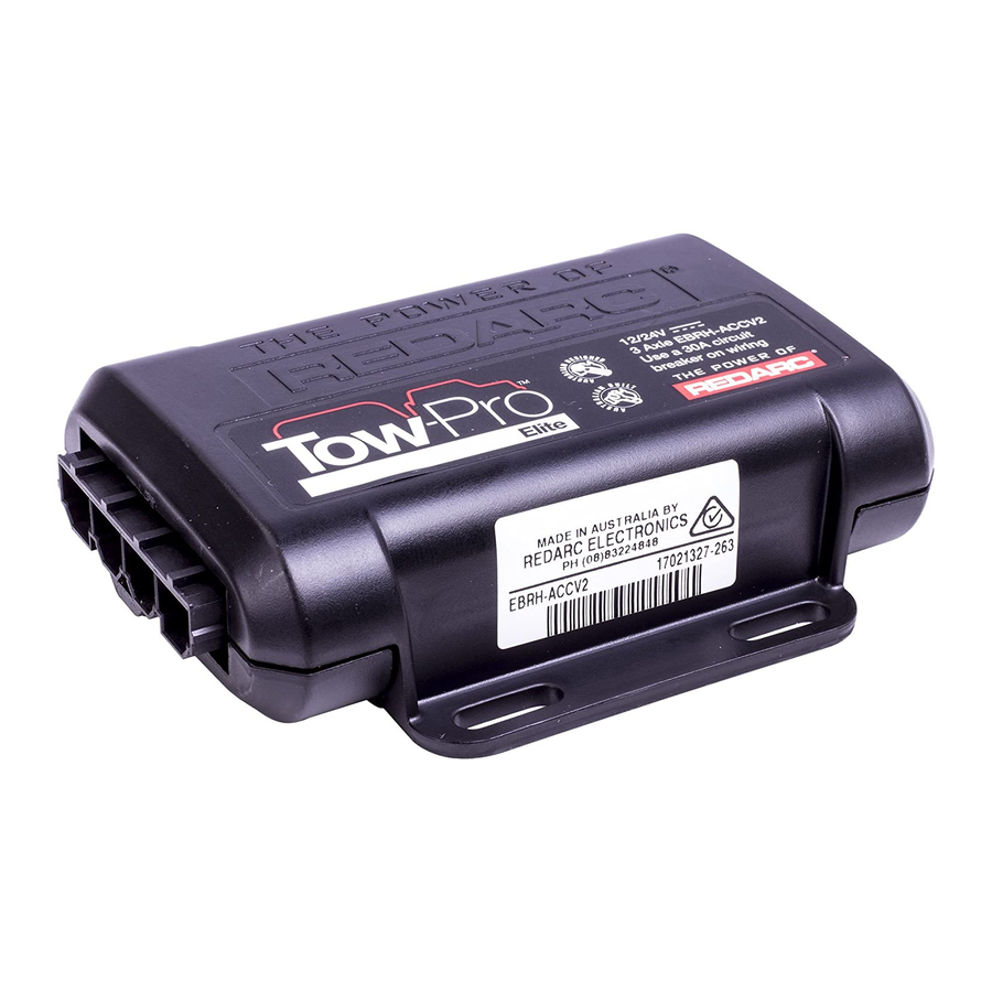
Scale CHECKING THE PRODUCT SERIAL NUMBER The image below indicates where the Product Serial Number on the Main Unit and on the Product Packaging. MADE IN AUSTRALIA BY REDARC ELECTRONICS PH +61 8 83224848 CAN ICES-3 (B)/NMB-3(B) 2005003460069 EBRH-ACCV3-NA The Serial Number Label contains the Part Number (circled in BLUE) and the Serial Number (circled in RED). -
Page 25: Fcc Declaration
FCC DECLARATION This device complies with part 15 of the FCC Rules. Operation is subject to the following two conditions: (1) This device may not cause harmful interference, and (2) this device must accept any interference received, including interference that may cause undesired operation Note: This equipment has been tested and found to comply with the limits for a Class B digital device, pursuant to part 15 of the FCC Rules. -
Page 26: Notes
NOTES... -
Page 27: Two Year Product Warranty
24 for prompt and efficient diagnosis and product support. REDARC Corporation Pty Ltd (“REDARC”) offers a warranty in respect of its Products purchased from an authorized distributor or reseller of REDARC by a person who is the original retail purchaser (“Purchaser”), on the terms and conditions, and for the duration, outlined below in this document (“Warranty”). - Page 28 United States +1 (704) 247-5150 Canada +1 (604) 260-5512 US Patent Number US 9,446,747 US Trademark 5,353,114 Mexico Canadian Trademark TMA991,361 +52 (558) 526-2898 Copyright © 2020 REDARC Corporation Pty Ltd. All rights reserved. redarcelectronics.com INST72 - REV1...
Need help?
Do you have a question about the TOW-PRO ELITE and is the answer not in the manual?
Questions and answers