Table of Contents
Advertisement
Quick Links
Advertisement
Table of Contents

Related Manuals for Redarc TVMS1280


Summary of Contents for Redarc TVMS1280
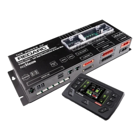
- Page 1 TVMS1280 12V 80A Total Vehicle Management System MODELS: TVMS1280 ƒ...
-
Page 2: Warnings & Safety Instructions
Do NOT alter or disassemble the system under any circumstances. All services or repairs must be returned to REDARC for repair. Incorrect handling or reassembly may result in a risk of electric shock or fire and may void the unit warranty. - Page 3 Use of an attachment not recommended or sold by REDARC may result in a risk of fire, electric shock, or injury to persons. Cable and fuse sizes are specified by various codes and standards which depend on the type of vehicle the system is installed into.
-
Page 4: Table Of Contents
CONTENTS WARNINGS & SAFETY INSTRUCTIONS ��������������������������������������������������������������������������������� INTRODUCTION ������������������������������������������������������������������������������������������������������������������������� Parts ������������������������������������������������������������������������������������������������������������������������������������������ Specifications ��������������������������������������������������������������������������������������������������������������������������� INSTALLATION ������������������������������������������������������������������������������������������������������������������������ System Layout (With REDARC Manager) ���������������������������������������������������������������������������������� Mounting ���������������������������������������������������������������������������������������������������������������������������������� DC Cable Size Requirements ���������������������������������������������������������������������������������������������������� Digital Inputs/Outputs ��������������������������������������������������������������������������������������������������������������� Fuses ��������������������������������������������������������������������������������������������������������������������������������������� Battery and Charger Connection ���������������������������������������������������������������������������������������������� Temperature Sensors ���������������������������������������������������������������������������������������������������������������... - Page 5 RedVision allows the user to turn lights, REDARC inverters, water pumps and other loads such as televisions, electric steps and fridges on or off, while displaying water levels, temperature, energy (battery power) consumption...
- Page 6 No instale ni utilice el producto RedVision (TVMS: Sistema de gestión total de vehículos) hasta que haya leído y comprendido el Manual de instalación y funcionamiento del sistema. REDARC recomienda que el sistema sea instalado por una persona debidamente calificada. Puede obtener una copia de este manual en español escaneando este código QR, visitando...
- Page 7 COMPATIBLE REDARC DEVICES REDARC Part Device Further Information Number Connection Wire DC/DC Chargers (BCDC) BCDC1220 BCDC1220-IGN 'BCDC Connection' (page 21) BCDC1225D BCDC1240D Battery Management Systems (The Manager) BMS1215S3 'Battery and Charger Connection' (page 20) BMS1230S2 CAN/R-BUS 'Manager30 Connection' (page 20) 'R-Bus Connection (Manager30)' (page 23)
-
Page 8: Introduction
INTRODUCTION PARTS Water Level Sensor Connectors are not supplied. Interface is compatible with AMP-171822-5 8 | Introduction... - Page 9 Lugs (4 AWG, M5 stud) RJ45 R-Bus Terminating Resistor RJ45 R-Bus Cable — 1 m (3") Black RJ12 REDARC Inverter Remote Cable — 3 m (9'10") Temperature Sensors — 3 m (9'10") Digital Input mating connector 10 A Output Connector — Red 10 A Output Connector —...
-
Page 10: Specifications
SPECIFICATIONS ELECTRICAL SPECIFICATIONS 12 V ⎓ System Voltage Maximum Charger Current 40 A Maximum Battery Current 80 A No. Switched Circuits 5 × 10 A Max, 5 × 30 A Max COMPLIANCE Regulatory Safety EN 61010.1 Environmental RoHS REACH Compliant Compliant GENERAL SPECIFICATIONS Distribution Box... - Page 11 DIMENSIONS DISTRIBUTION BOX DIMENSIONS 28 mm (1.1") Ø6 mm Ø11 mm Ø6 mm (0.23") (0.43") (0.23") 2.5 mm (0.1") 71.5 mm (2.81") 58 mm (2.28") 80 mm (3.14") 27 mm (1.06") 66 mm (2.59") 138 mm (5.43") Introduction | 11...
- Page 12 DISPLAY DIMENSIONS 7 mm 178 mm (7.00") (0.28") 11 mm ( 0.43") 18.5 mm (0.73") 158 mm (6.22") 11 mm (0.43") Optional Spacer 19 mm Ø4.5 mm (0.74") (0.17") × 4 15 mm 6 mm (0.59") Mounting Holes: 156 mm (6.14") (0.23") 12 | Introduction...
-
Page 13: Installation
Do not use this product to control safety critical devices or those that could cause harm if operated remotely (for example fume exhaust fans or lifters). SYSTEM LAYOUT (WITH REDARC MANAGER) See the Manager30 manual for full wiring details. Display... -
Page 14: Mounting
MOUNTING The Distribution Box should be mounted as close as possible to the source battery(s) and Battery Charger to avoid voltage drop. MOUNTING THE DISTRIBUTION BOX The Distribution Box may be mounted in any orientation but must be mounted onto a flat, solid surface using 4 ×... - Page 15 MOUNTING THE DISPLAY The full-size Display Mounting Template is located on page 49. The Display should be mounted on a flat, solid surface in a sheltered location, ideally inside the vehicle. It is acceptable to mount the Display in any location that it is protected from harsh environmental conditions such as rain, dust or constant direct sunlight.
-
Page 16: Dc Cable Size Requirements
4 AWG Connections OUTPUT WIRE DIAMETER SELECTION REDARC recommends the installer use suitably rated cable and fuses for the load connected. Refer to the table below for the 10 and 30 A connector terminal sizes and maximum cable sizes. Connection... -
Page 17: Digital Inputs/Outputs
DIGITAL INPUTS/OUTPUTS Digital Digital Input 1 Input 3 Start Battery Positive (+) Start Battery Negative (–) Digital Input 2 The Distribution Box incorporates 3 digital inputs. The Digital Inputs (1, 2, and 3) can be configured to switch Distribution Box output loads On/Off when triggered (for example, to turn off all loads except a fridge when the vehicle ignition is on). -
Page 18: Fuses
FUSES FUSE LOCATIONS Spare Charger Fuse 50 A Override Switches Charger Fuse 10 A Max. 30 A Max. Circuit Fuses Circuit Fuses Spare Fuses The Distribution Box load output channels are protected by standard blade fuses located in the fuse panel. - Page 19 LOAD NEGATIVES Wire each load positive (+) and negative (–) to the applicable output channel. Alternatively, load negatives may be connected at a suitable chassis grounding point. CAUTION Risk of damage to the system. Do NOT connect a load negative (–) to the chassis AND to the applicable negative (–) output channel as this may cause damage to the Distribution Box under some circumstances.
-
Page 20: Battery And Charger Connection
BATTERY AND CHARGER CONNECTION The Distribution Box is intended to be used in conjunction with the Manager30, but alternatively, it can be used with a REDARC BCDC charger. BATTERY CONNECTION Wire the Auxiliary Battery Positive (+) to the Distribution Box through the supplied 80 A MIDI fuse —... - Page 21 40 A and below. Higher current chargers requiring a fuse larger than 50 A should be connected directly to the Auxiliary Battery with appropriate fusing and not via the Distribution box. Source Battery TVMS1280 80 A Fuse Fuse Holder BROWN BLACK...
-
Page 22: Temperature Sensors
TEMPERATURE SENSORS Two 3 metre (10-ft) temperature sensors are included with TVMS1280 and are able to sense from −40°C to +80°C (−40°F to +176°F). The two supplied temperature sensors may be added to the system by simply plugging into the two interfaces on the Distribution Box. -
Page 23: R-Bus Connection (Manager30)
4. When a Manager30 is used, the terminating resistor for the other end of the Bus is inbuilt in the Battery Sensor. If a Manager30 is not used, the supplied terminating resistor should be inserted into one of the ports on the TVMS1280 Distribution Box. 5. If using a BMS1230S2, BMS1230S2-NA,or BMS1215S3, connect to the RedVision and Battery Sensor by using the T-Piece supplied with the Manager. - Page 24 CAN-Bus Connection — BMS1230S2 / BMS1230S2-NA / BMS1215S3 Display Some Manager models do not have a second R-Bus port. A T-piece must be used to connect the BMS and the Battery Sensor to the TVMS1280. BMS1230S2 / TVMS1280 BMS1230S2-NA / BMS1215S3...
-
Page 25: Water Level Sensors
WATER LEVEL SENSORS Up to six water level sensors may be connected to the Distribution Box. 2–5 PIN TANK SENDERS Most 2–5 pin conductive tank sensors can be used in conjunction Wire 5 (if applicable) with an AMP-171822-5 connector Wire 4 (if applicable) (not supplied). -
Page 26: Optional Inverter Connection
Rear (12V end) of Inverter REDARC's RS/RS2-Series inverters may be connected to the Distribution Box to allow the user to switch the inverter on/off, via the Display. The inverter should be mounted as close as possible to the Auxiliary battery (Refer to the inverter's user manual for further installation information including fuse and cable sizing.) -
Page 27: System Configuration
Configure the settings of your TVMS1280 using your smartphone via Bluetooth ® The RedVision® App and its interactions with the TVMS1280 have not been tested on all smartphone models. Visit the application pages within your App store to view compatibility details. -
Page 28: Load A Configuration
LOAD A CONFIGURATION 1. Following the Bluetooth pairing instructions will require selecting your Display. Once successfully ® paired, the App will download your current system configuration, save it and then you should see the RedVision Configurator Main Menu. The App has now downloaded your RedVision system settings which you can now change. -
Page 29: Configure Distribution Box - Load Disconnect Settings
From the Main Menu, select Battery Sensor. The Configure Battery Sensor page allows you to set the Battery Type, Size and Maximum Charge Current along with SoC and Voltage alarm levels. The default settings are: ƒ Battery Type: Gel ƒ... - Page 30 'Voltage' trigger level. The unit will reconnect the loads when the measured voltage rises 0.5 V above the user defined trigger level. *1 BMS triggers available when installed with a REDARC Manager battery charger. *2 Available on Distribution Boxes with serial numbers after 21040571770001.
-
Page 31: Configure Distribution Box - Channels
CONFIGURE DISTRIBUTION BOX — CHANNELS From the Main Menu, select Distribution Box > Channels The Channel Settings page allows you to customise each of the connections to your RedVision Distribution Box. Simply put, you can tell RedVision what you have connected to it, and how you want RedVision to control that channel. - Page 32 (i.e. Clean, Black, Brown etc.) ƒ Inverter Settings — Allows enabling of Inverter remote control should a REDARC RS series inverter be connected to the ‘Optional Inverter Connection’ port on the RedVision Distribution Box.
-
Page 33: Configure Display - Soft Keys
ƒ User Control — This allows the selected channel to be turned ON or OFF using the Soft Keys on the display or via the Buttons on the App. In User Controlled mode, ON only during button press and/or Input Override can be selected. The channel will default to have both of these turned OFF. -
Page 34: Configure Display - Home Screen
From the Configure Soft Keys Menu, select the slot you wish to set up, then select choose. Select a Channel from the list of available Channels. CONFIGURE DISPLAY — HOME SCREEN From the Main Menu, select Display > Home Screen. ... -
Page 35: Configure Display - Status Screen
ƒ Voltage Channels — These drop down menus allows you to select the Voltage Sensor Channels that appear on the RedVision Display. CONFIGURE DISPLAY — STATUS SCREEN From the Main Menu, select Display > Status Screen, then Select your Screen or Add a new Status Screen. -
Page 36: Configure Display - Temperature Units
CONFIGURE DISPLAY — TEMPERATURE UNITS From the Main Menu, select Display > Temperature Units. The Temperature Screen Settings page allows configuration of the RedVision Display Temperature Units. Select if you would like your units displayed in Celsius or Fahrenheit, then select Save. 36 | System Configuration... -
Page 37: User Guide
USER GUIDE THE DISPLAY Time Notification Bar Temperature Up/Down indication function Softkeys Softkeys Softkey Locked Device active indication Up/Down Left/Right arrow arrow Left/Right function Power Button The Display is the main user interface for the RedVision System. It brings information and control to one place without the need for multiple displays and control panels. - Page 38 NAVIGATION The Left/Right buttons are used to navigate the pages on the centre of the screen. The Up/Down buttons are used to navigate through options found on other pages or to cycle through devices on the Home Page when a Distribution Box is connected. The Left/Right and Up/Down functions are indicated on the screen.
-
Page 39: Basic Screens
BASIC SCREENS HOME SCREEN The Home Screen shows the system overview in the centre, with connected devices managed by Soft Keys to the left and right. The system overview shows BMS status and Water Tank levels. Pushing the Up/Down arrows cycles through all available devices. - Page 40 The Soft Key on the left links to the Charging Source information page. Pushing the down arrow displays the Distribution Box Info. screen (when used with a REDARC RedVision Distribution Box). DISTRIBUTION BOX INFORMATION The Distribution Box information screen provides...
-
Page 41: Display Settings
DISPLAY SETTINGS The Display Settings screen allows setup and modification of Display specific settings. Factory Settings Key Sound Display Settings Key Backlight Home Timeout 1 min Standby Timeout 1 min Brightness Minimum Brightness Maximum 100% Clock Format 12 Hour DISPLAY SETTING ICONS Returns to the Home Screen. -
Page 42: System Settings
Mode between Storage and Touring. Storage Mode will switch off all loads and set the Manager into Storage Mode should one be connected. Opens the About Us screen. This screen provides contact information for REDARC. Opens the RBus Diagnostics screen. This screen provides a serial number for each REDARC device connected to the system. -
Page 43: Bms Settings
BMS SETTINGS When a Battery Management System is connected, the system will allow setup and modification of a number of BMS settings. BMS Settings SYSTEM SETTING ICONS Returns to the Home Screen. Opens the Battery Information screen. This screen allows the user to set their battery type and size. -
Page 44: Distribution Box Settings
DISTRIBUTION BOX SETTINGS This Settings screen allows setup and modification of the Distribution Box Load Disconnect feature and provides information on the Distribution Box’s channel setup. Distribution Box settings can only be changed by the system installer. Distribution Box SYSTEM SETTING ICONS Returns to the Home Screen. -
Page 45: Fault Display
FAULT DISPLAY Fault screens will be shown if either an output fuse is blown, the Manager has a fault, or if the unit encounters a switching fault. TVMS Output Fuse blown FUSE FAULTS When a fuse fault is detected (i.e., a fuse is blown) the output channel will be turned off and the corresponding icon on the display will be shown in red. -
Page 46: Additional Information
ADDITIONAL INFORMATION CHECKING THE PRODUCT SERIAL NUMBER The serial numbers for each REDARC device connected to the system can be displayed on the R-Bus diagnostics screen — see 'System Settings' (page 39). The Product Serial Number is located on the Distribution Box and on the Display. -
Page 47: Compliance Information
ƒ Connect the equipment into an outlet on a circuit different from that to which the receiver is connected. ƒ Consult the dealer or an experienced radio/ TV technician for help Any changes or modifications not expressly approved by REDARC could void the user’s... -
Page 48: Limited Warranty
LIMITED WARRANTY For full warranty terms and conditions, visit the Warranty page of the REDARC website. Refer to the web address and contact details applicable to your region. Australia, New Zealand & Europe North America www.redarc.com.au/warranty www.redarcelectronics.com/warranty REDARC Electronics Pty Ltd... -
Page 49: Display Mounting Template | 49
Display Mounting Template | 49... - Page 50 NOTES...
- Page 51 Lonsdale SA 5160 Australia Design, product configuration and technical specifications are subject to change without notice. | Copyright © 2022 REDARC Electronics Pty Ltd. All rights reserved. REDARC® and THE POWER OF REDARC® are trademarks of REDARC Electronics Pty Ltd.
- Page 52 CONTACT Tech Support 1300 REDARC Head Office +61 8 8322 4848 New Zealand +64 9 222 1024 UK & Europe +44 (0)20 3930 8109 +1 (704) 247 5150 Canada +1 (604) 260 5512 Mexico +52 (558) 526-2898 redarcelectronics.com WARTVMS1280-11...
Need help?
Do you have a question about the TVMS1280 and is the answer not in the manual?
Questions and answers