Table of Contents
Advertisement
Advertisement
Table of Contents

Related Manuals for Redarc Redvision TVMS1280


Summary of Contents for Redarc Redvision TVMS1280
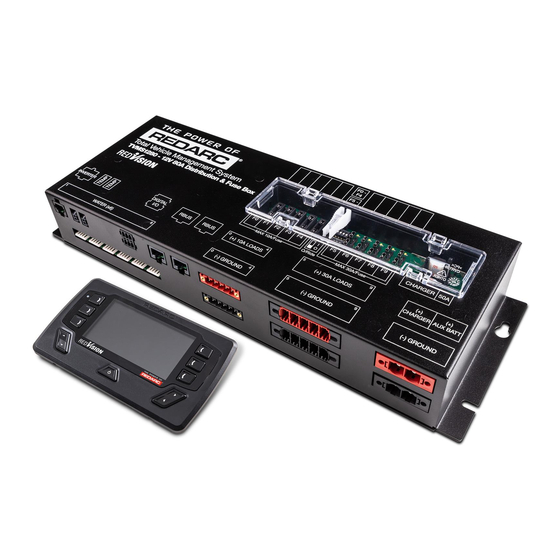
- Page 1 Total Vehicle Management System TVMS1280...
-
Page 2: Warnings & Safety Instructions
REDARC for repair. Incorrect handling or reassembly may result in a risk of electric shock or fi re and may void the unit warranty. Use of an attachment not recommended or sold by REDARC may result in a risk of fi re, electric shock, or injury to persons. - Page 3 NEVER SMOKE OR ALLOW A SPARK OR FLAME NEAR A BATTERY AS THESE MAY CAUSE THE BATTERY TO EXPLODE. TO REDUCE THE RISK OF A SPARK NEAR A BATTERY WHEN CONNECTING THE BATTERY INSTALLED IN A VEHICLE TO THE TVMS, ALWAYS DO THE FOLLOWING: Wire the Output Connector before connecting it to the Distribution Box.
-
Page 4: Table Of Contents
CONTENTS Table of Contents Warnings & Safety Instructions Features and Benefi ts 1. Introduction 1.1 Kit Contents 1.2 Specifi cations 1.3 Compatible Devices 1.4 Dimensions 2. Installation Guide 2.1 System Layout 2.2 Mounting Instructions 2.3 DC Cable Size Requirements 2.4 Digital I/Os 2.5 Fuses 2.6 Battery &... -
Page 5: Features And Benefi Ts
• Fuse up to 10 circuits plus charger circuit • Automate output functionality • Works with a range of REDARC charging systems When used in conjunction with a REDARC RS Series Inverter. When used in conjunction with a REDARC Manager. -
Page 6: Introduction
INTRODUCTION Kit Contents Distribution Box (TVMS1280-DB): Part Distribution box Fuse cover panel (fi tted) Fuse puller tool (fi tted) 80A midi fuse Midi fuse holder 50A midi fuses (fi tted) Crimp terminals for fuse holder 0.5m R-Bus Cable 3m Inverter Remote Cable R-Bus Terminator Temperature Sensors Power cable mating connectors... -
Page 7: Specifi Cations
2 years Electrical Specifi cations System Voltage Maximum Charger Current Maximum Battery Current No. Switched Circuits 5 x 10A Max, 5 x 30A Max Compatible Devices Type REDARC Part Device Relevant section of Number Connection Wire this manual BCDC1220 BCDC1220-IGN Chargers Section 2.6... -
Page 8: Dimensions
INTRODUCTION Dimensions Ø6mm 2.5mm 71.5mm 28mm 58mm 80mm 66mm 27mm 138mm Figure 1.4.1 - Distribution Box Dimensions... - Page 9 INTRODUCTION 18.5mm 178mm 11mm Optional Spacer 11mm 158mm 19mm 15mm 156mm Figure 1.4.2 - Display Dimensions...
-
Page 10: Installation Guide
INSTALLATION GUIDE System Layout Distribution Box Display Terminating Resistor T-Piece To Ignition To Alternate Trigger Signals Water Level Sensors Small Loads Large Loads Battery Sensor Temperature Sensors Auxiliary Battery Inverter Do not use this product to control safety critical devices or those that could cause harm if operated remotely (for example fume exhaust fans or lifters). -
Page 11: Mounting Instructions
INSTALLATION GUIDE Mounting Instructions The Distribution Box should be mounted as close as possible to the auxiliary battery(s) and Battery Charger to avoid voltage drop. 2.2.1 Mounting the Distribution Box The Distribution Box may be mounted in any orientation but must be mounted onto a fl... - Page 12 INSTALLATION GUIDE 2.2.2 Mounting the Display The Display should be mounted inside the vehicle (Refer to page 48 for a 1:1 cutout template). It is however acceptable to mount the Display in any convenient location, as long as it is protected from harsh environments such as being exposed to rain or severe amounts of dust or full-time direct sunlight.
- Page 13 INSTALLATION GUIDE 2.2.3 Removing the Display Fascia...
- Page 14 INSTALLATION GUIDE Refer to page 48 for a 1:1 cutout template 2.2.4 Flush Mount Drill/Cut Dimensions NOT TO SCALE Refer to page 48 for a 1:1 cutout template 2.2.5 Surface Mount Drill/Cut Dimensions NOT TO SCALE Refer to page 48 for a 1:1 cutout template Ø45mm...
-
Page 15: Dc Cable Size Requirements
Positive & Ground 2.3.2 Output Wire Diameter Selection REDARC recommends the installer use suitably rated cable and fuses for the load connected. Refer to the table below for the 10 and 30 amp connector terminal sizes and maximum cable sizes. -
Page 16: Digital I/Os
INSTALLATION GUIDE Digital I/Os Digital Inputs Start Battery Positive Start Battery Negative The Distribution Box incorporates 3 digital inputs. The digital inputs, , can be confi gured to switch Distribution Box output loads on/off when triggered (for example, to turn off all loads except a fridge when the vehicle ignition is on). -
Page 17: Fuses
INSTALLATION GUIDE Fuses Spare Charger Fuse 50A Charger Fuse Override Switches 30A Max Circuit Fuses 10A Max Circuit Fuses Spare Fuses 2.5.1 Fuse Locations The Distribution Box load output channels are protected by standard blade fuses located in the fuse panel: Part Type 10A Max Loads... - Page 18 INSTALLATION GUIDE Master Override Indicator Master Override switch Blown Fuse Indicators 10A max circuit 30A max circuit override switches override switches Note: Fuse values may vary from those shown in this diagram, depending on individual system requirements 2.5.3 Blown Fuse Indicators A blown fuse is indicated by an illuminated indicator (white) above the blown fuse.
-
Page 19: Battery & Charger Connection
INSTALLATION GUIDE Battery & Charger Connection 2.6.1 Battery Connection Wire the Auxiliary Battery Positive (+) to the Distribution Box through the supplied 80A MIDI fuse - this fuse should be mounted as close as practical the battery. Refer to Section 2.3 for cable sizing. Wire the distribution box Battery Ground (-) to either a suitable grounding point (i.e. - Page 20 INSTALLATION GUIDE 2.6.3 Charger Connection (BCDC) The BCDC should be mounted as close as possible to the Distribution Box. Connect the BCDC’s battery output positive (+) and Ground ( ) to the Distribution Box Charger (+) and Ground (-) connections. Refer to Section 2.3 for cable sizing.
-
Page 21: Temperature Sensors
Two 3 metre temperature sensors are included with RedVision and are able to sense from -40°C to +80°C. The two supplied temperature sensors may be added to the system by simply plugging into the two sockets on the Distribution Box. Additionally, the REDARC sensors in the table below are also compatible: Part Sensing... -
Page 22: R-Bus Connection
INSTALLATION GUIDE R-Bus Connection (Manager 15 or 30) Terminating T-Piece Resistor Battery Sensor Display 2.8.1 Connecting the RedVision R-Bus RedVision uses an R-Bus communication system to link components. 1. Use the supplied 1 metre RJ45 cable to connect the Battery Management System to either of the sockets on the Distribution Box. - Page 23 A terminating resistor must be present at each end to terminate the network. REDARC Manager 15 & 30 have this resistor built in, thus removing the need to add an extra terminating resistor to one end of the system. The other end of the network should be terminated by inserting the supplied Terminating Resistor into the last device in the network (for example, into the RedVision Display in the diagram on page 22).
-
Page 24: Water Level Sensors
INSTALLATION GUIDE Water Level Sensors Up to six water level sensors may be connected to the Distribution Box. RV Electronics 5 pin tank senders The Distribution Box has direct compatibility with the following sensors from RV Electronics: • SP0004 • SP0011 •... -
Page 25: Optional Inverter Connection
Rear (12V end) of Inverter REDARC’s RS-Series inverters may be connected to the Distribution Box to allow the user to monitor power consumption, output load and switch the inverter on/off, all via the Display. Note that the 350W model inverter (R-12-350RS) offers power on/off control only. -
Page 26: System Confi Guration
SYSTEM CONFIGURATION RedVision Confi gurator App. The RedVision ‘Confi gurator’ App allows the user to setup and/or customise their RedVision setup from the convenience of their mobile device. ® If this is your fi rst time using the Confi gurator App, please follow the Bluetooth pairing instuctions found in Section 4.3.1. -
Page 27: Confi Gure Charger
SYSTEM CONFIGURATION Confi gure Charger The Confi gure BMS (Charger) page allows you to setup the Input Trigger and Disconnect When settings for a Manager15 or Manager30 should one be connected. • The default Input trigger setting is ‘Automatic’. From the Main Menu: •... -
Page 28: Confi Gure Distribution Box - Load Disconnect Settings
SYSTEM CONFIGURATION Confi gure Distribution Box - Load Disconnect Settings From the Main Menu: 1. Tap the Distribution Box Button, then 2. Tap the Load Disconnect Settings Button The Confi gure TVMS Disconnect page allows you to set the Disconnect Trigger for the RedVision system. -
Page 29: Confi Gure Distribution Box - Channels
SYSTEM CONFIGURATION Confi gure Distribution Box - Channels From the Main Menu: 1. Tap the Distribution Box Button, then 2. Tap the Channels Button The Channel Settings page allows you to customise each of the connections to your RedVision Distribution Box. Simply put, you can tell RedVision what you have connected to it, and how you want RedVision to control that channel. - Page 30 (i.e. Clean, Black, Brown etc.) 5. Inverter Settings - Allows enabling of Inverter communications settings should a REDARC RS series inverter be connected to the ‘Optional Inverter Connection’ port on the RedVision Distribution Box.
- Page 31 SYSTEM CONFIGURATION From the Channel Settings Menu: • Tap the Channel that you wish to modify There are three main Logic Confi guration types that can be used: 1. Always On - This will ensure that the selected channel is Always On. This could be used for a fridge, for example, so that you don’t accidentally turn it OFF.
-
Page 32: Confi Gure Display - Soft Keys
SYSTEM CONFIGURATION Confi gure Display - Soft Keys The Confi gure Soft Keys page allows allocation of any Output Channels (including the Inverter channel) that have ‘Channel Enabled’ selected. The 6 empty slots shown in this page on your device correspond to the same locations on the RedVIsion From the Main Menu: Display once programmed. -
Page 33: Confi Gure Display - Home Screen
SYSTEM CONFIGURATION Confi gure Display - Home Screen From the Main Menu: 1. Tap the Display Button, then 2. Tap the Home Screen Button The Home Screen Settings page allows confi guration of the RedVision Display Home Screen. Home Screen Layout - This drop down menu allows selection of a number of Home Screen combinations. -
Page 34: Confi Gure Display - Status Screen
SYSTEM CONFIGURATION Confi gure Display - Status Screen From the Main Menu: 1. Tap the Display Button, then 2. Tap the Status Screen Button, then 3. Select your Screen or Add a new Status Screen The Status Screen Settings page allows confi guration of the RedVision Display Status Screens. -
Page 35: Confi Gure Display - Temperature Units
SYSTEM CONFIGURATION Confi gure Display - Temperature Units From the Main Menu: 1. Tap the Display Button, then 2. Tap the Temperature Units Button The Temperature Screen Settings page allows confi guration of the RedVision Display Temperature Units. Simply select if you would like your units displayed in Celsius or Fahrenheit and hit save. -
Page 36: User Guide
USER GUIDE The Display Time Notification Bar Temperature Up/Down indication function Softkeys Softkeys Softkey Locked Device active indication Up/Down Left/Right arrow arrow Left/Right function Power Button The Display is the main user interface for the RedVision System. It brings information and control to one place without the need for multiple displays and control panels. - Page 37 USER GUIDE 4.1.1 Navigation The Left/Right buttons are used to navigate the pages on the centre of the screen. The Up/Down buttons are used to cycle through devices on the Home Page or to navigate through options found on other pages. The Left/Right and Up/Down functions are indicated on the screen.
- Page 38 USER GUIDE 4.1.5 Basic Screens Home Screen The Home Screen shows the system overview in the centre, with connected devices managed by Soft Keys to the left and right. The system overview shows BMS status and Water Tank levels Pushing the Up/Down arrows cycles through all available devices.
- Page 39 Charging Source information page. Pushing the down arrow displays When used with a REDARC MANAGER system. the Distribution Box Info. screen* When used with a REDARC RedVision Distribution Box. Distribution Box Information The Distribution Box information Distribution Box screen provides information 14.4V...
- Page 40 USER GUIDE Inverter Information The Inverter Information screen Inverter provides information if a REDARC Output Power inverter is connected to the system. 500W The Output Power reading shows the instantaneous output of the Output Voltage 235V inverter as a proportion of the maximum possible output.
- Page 41 USER GUIDE 4.1.6 Display Settings Factory Settings Display Settings Key Sound: Key Backlight: Home Timeout: 1 min Standby Timeout: 1 min Brightness Minimum: Brightness Maximum: 100% Clock Format: 12 Hour The Display Settings screen allows setup and modifi cation of Display specifi c settings as outlined below.
- Page 42 REDARC This icon links to the RBus Diagnostics screen. This screen provides a serial number for each REDARC device connected to the system. More information on the selected device can be found by clicking the top right Soft Key This icon links to the Fault History screen.
- Page 43 USER GUIDE 4.1.8 BMS Settings BMS Settings When a Battery Management System is connected, the system will allow setup and modifi cation of a number of BMS settings as outlined below. This icon will return to the Home Screen This icon links to the Battery Information screen. This screen allows the user to set their battery type and size.
- Page 44 USER GUIDE 4.1.9 Distribution Box Settings Distribution Box This Settings screen allows setup and modifi cation of the Distribution Box Load Disconnect feature and provides information on the Distribution Box’s channel setup. Distribution Box settings can only be changed by the system installer. This icon will return to the Home Screen This icon links to the Channel Information screen.
-
Page 45: Fault Display
USER GUIDE Fault Display TVMS Output Fuse blown Fault screens will be shown if either an output fuse is blown, a connected Inverter or Manager has a fault or if the unit encounters a switching fault. Fuse Faults When a fuse fault is detected (ie, a fuse is blown) the output channel will be turned off and the corresponding icon on the display will be shown in red. -
Page 46: The Redvision App
It also provides the user with the ability to monitor water levels, temperature, energy (battery power) consumption and storage, with the battery information available when used with a REDARC Manager battery management system. The RedVision App replicates MOST of the display and switching features of the Display. - Page 47 Pairing Instructions 1. Install the RedVision or Confi gurator App (scan the corresponding QR code or search for “REDARC” on your device’s app store) 2. On the Display, press Left, navigate to display RedVision ® settings & press the Bluetooth Soft Key –...
- Page 48 USER GUIDE 4.3.2 Subsequent Connections Once a smartphone has been paired with a RedVision Display, it will automatically reconnect with that Display when the app is opened. If you have multiple Redvision Displays paired and you want to switch between which is connected to your smart phone, tap on the 3 gear symbol on the top left of the app.
-
Page 49: Display Drill Template
DISPLAY DRILL/CUTOUT TEMPLATE... - Page 50 THIS PAGE INTENTIONALLY LEFT BLANK...
-
Page 51: Two Year Product Warranty
• Friendly, personalised, professional service and product support In the unlikely event that a technical issue arises with a Redarc product, customers are encouraged to initially contact the Redarc Technical Support Team on (08) 8322 4848 power@redarc.com.au for prompt and effi cient diagnosis and product support. - Page 52 Free technical assistance! please contact REDARC Electronics 23 Brodie Road North, Lonsdale SA (08) 8322 4848 power@redarc.com.au www.redarc.com.au Copyright © 2018 REDARC Electronics Pty Ltd. All rights reserved. www.redarc.com.au WARTVMS1280-UM - REV5...
Need help?
Do you have a question about the Redvision TVMS1280 and is the answer not in the manual?
Questions and answers
where would I find the TVMS fuse on my Redarc system