
Related Manuals for Pickering 40-760


Summary of Contents for Pickering 40-760
- Page 1 40-760/1A/2/3A/4/5A/6/7A User Manual PXI 50Ω 600MHz RF Multiplexer Modules pickeringtest.com Issue 2.1 June 2021...
- Page 2 © COPYRIGHT (2021) PICKERING INTERFACES. ALL RIGHTS RESERVED. No part of this publication may be reproduced, transmitted, transcribed, translated or stored in any form, or by any means without the written permission of Pickering Interfaces. Technical details contained within this publication are subject to change without notice.
- Page 3 Pickering Interfaces strives to fulfil all relevant environmental laws and regulations and reduce wastes and releases to the environment. Pickering Interfaces aims to design and operate products in a way that protects the environment and the health and safety of its employees, customers and the public. Pickering Interfaces endeavours to develop and manufacture products that can be produced, distributed, used and recycled, or disposed of, in a safe and environmentally friendly manner.
-
Page 4: Product Safety
If this product is heavy reference should be made to the safety instructions for provisions of lifting and moving. STATIC SENSITIVE To indicate that static sensitive devices are present and handling precautions should be followed. REED RELAY MODULE 40-110/115/120/125 50Ω 600ΜHz RF MUX 40-760/761A/762/763A/764/765A/766/767A Page (IV) Page (IV) -
Page 5: Table Of Contents
Pre Operation Checks ............3.1 Hardware Installation ............3.2 Software Installation .............3.2 Testing Operation ..............3.3 Section 4 Programming Guide ..............4.1 Programming Options For Pickering PXI Modules ....4.1 Programming The RF Multiplexer ........4.2 Section 5 Connector Information ..............5.1 Section 6 Trouble Shooting .................6.1 Section 7 Maintenance Information ............7.1... - Page 6 THIS PAGE INTENTIONALLY BLANK 50Ω 600ΜHz RF MUX 40-760/761A/762/763A/764/765A/766/767A Page (VI)
-
Page 7: Warnings And Cautions
Unused slots in the host chassis are populated with blanking plates to prevent access to user I/O signals that may be present. Blanking panels are available to order from Pickering in a variety of slot widths. If the product is not used in this manner for example by using an extender card then additional care must be taken to avoid contact with exposed signals. - Page 8 THIS PAGE INTENTIONALLY BLANK 50Ω 600ΜHz RF MUX 40-760/761A/762/763A/764/765A/766/767A Page (VIII)
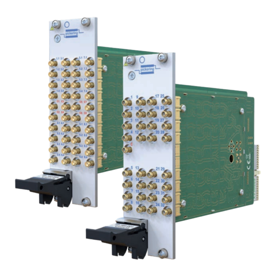
- Page 9 (2, 4 or 8 Banks) SP8T (1, 2 or 4 Banks) SP8T Terminated The 40-760 series is a range of 50 Ω RF multiplexers (1, 2 or 4 Banks) available in SP4T, SP8T, SP16T and SP32T formats. All multiplexers have the option of automatic termination which offers the advantage of reducing standing waves which can cause degradation in isolation and crosstalk.
- Page 10 Humidity: Up to 90 % non-condensing Altitude: 15000 m RF plots up to 1 GHz for all versions in the 40-760 range are shown in the User Manual for: PXI & CompactPCI Compliance • Insertion Loss The module is compliant with the PXI Specification •...
- Page 11 Ordering Information 600 MHz RF MUX, 40-760/1A/2/3A/4/5A/6/7A Product Order Codes Mating Connectors & Cabling SP4T 600 MHz RF MUX For connection accessories for the 40-760 range please Single PXI Slot Versions: refer to the 90-011D RF Cable Assemblies data sheet...
- Page 12 We provide a full range of supporting cable and connector solutions for all our switching products—20 connector families with 1200+ products. We offer everything from simple mating connectors to complex cables assemblies and terminal blocks. All assemblies are manufactured by Pickering and are guaranteed to mechanically and electrically mate to our modules. Connectors & Backshells...
- Page 13 600 MHz RF MUX, 40-760/1A/2/3A/4/5A/6/7A Programming Pickering provide kernel, IVI and VISA (NI & Keysight) drivers which are compatible with all Microsoft supported versions of Windows and popular older versions. For a list of all supporting operating systems, please see: pickeringtest.com/os...
-
Page 14: Rf Performance Plots
RF PERFORMANCE PLOTS: 40-760-002 Typical insertion loss plot for all channels of Typical VSWR plot for all channels of 40-760-002 (Dual SP4T RF MUX) 40-760-002 (Dual SP4T RF MUX) Typical crosstalk plot between channels for Typical crosstalk plot between banks for... - Page 15 RF PERFORMANCE PLOTS: 40-760-004 Typical insertion loss plot for all channels of Typical VSWR plot for all channels of 40-760-004 (Quad SP4T RF MUX) 40-760-004 (Quad SP4T RF MUX) Typical crosstalk plot between channels for Typical crosstalk plot between banks for...
- Page 16 Typical channel insertion loss plot for banks 1 to 4 of Typical channel insertion loss plot for banks 5 to 8 of 40-760-008 (Octal SP4T RF MUX) 40-760-008 (Octal SP4T RF MUX) Typical channel VSWR plot for banks 1 to 4 of...
- Page 17 SECTION 1 - TECHNICAL SPECIFICATION pickering RF PERFORMANCE PLOTS: 40-760-008 - CONTINUED Typical channel crosstalk plot for banks 1 to 4 of Typical channel crosstalk plot for banks 5 to 8 of 40-760-008 (Octal SP4T RF MUX) 40-760-008 (Octal SP4T RF MUX)
- Page 18 Typical terminated VSWR plot for all channels of Typical crosstalk plot between channels for 40-761A-002 (Dual SP4T Terminated RF MUX) 40-761A-002 (Dual SP4T Terminated RF MUX) Typical crosstalk plot between banks for 40-761A-002 (Dual SP4T Terminated RF MUX) 50Ω 600ΜHz RF MUX 40-760/761A/762/763A/764/765A/766/767A Page 1.10...
- Page 19 Typical terminated channel VSWR plot for banks 1 & 2 Typical terminated channel VSWR plot for banks 3 & 4 Quad SP4T Terminated RF MUX of 40-761A-004 (Quad SP4T Terminated RF MUX) of 40-761A-004 ( 50Ω 600ΜHz RF MUX 40-760/761A/762/763A/764/765A/766/767A Page 1.11...
- Page 20 SECTION 1 - TECHNICAL SPECIFICATION pickering RF PERFORMANCE PLOTS: 40-761A-004 - CONTINUED Typical crosstalk plot between channels for Typical crosstalk plot between banks for 40-761A-004 (Quad SP4T Terminated RF MUX) 40-761A-004 (Quad SP4T Terminated RF MUX) 50Ω 600ΜHz RF MUX 40-760/761A/762/763A/764/765A/766/767A Page 1.12...
- Page 21 40-761A-008 (Octal SP4T Terminated RF MUX) Typical channel VSWR plot for banks 1 to 4 of Typical channel VSWR plot for banks 5 to 8 of 40-761A-008 (Octal SP4T Terminated RF MUX) 40-761A-008 (Octal SP4T Terminated RF MUX) 50Ω 600ΜHz RF MUX 40-760/761A/762/763A/764/765A/766/767A Page 1.13...
- Page 22 Typical terminated channel VSWR plot for banks 4 to 6 of 40-761A-008 (Octal SP4T Terminated RF MUX) of 40-761A-008 (Octal SP4T Terminated RF MUX) Typical terminated channel VSWR plot for banks 7 & 8 of 40-761A-008 (Octal SP4T Terminated RF MUX) 50Ω 600ΜHz RF MUX 40-760/761A/762/763A/764/765A/766/767A Page 1.14...
- Page 23 40-761A-008 (Octal SP4T Terminated RF MUX) Typical bank crosstalk plot for banks 1 to 4 of Typical bank crosstalk plot for banks 5 to 8 of 40-761A-008 (Octal SP4T Terminated RF MUX) 40-761A-008 (Octal SP4T Terminated RF MUX) 50Ω 600ΜHz RF MUX 40-760/761A/762/763A/764/765A/766/767A Page 1.15...
- Page 24 Typical insertion loss plot for all channels of Typical VSWR plot for all channels of 40-762-001 (Single SP8T RF MUX) 40-762-001 (Single SP8T RF MUX) Typical crosstalk plot between channels for 40-762-001 (Single SP8T RF MUX) 50Ω 600ΜHz RF MUX 40-760/761A/762/763A/764/765A/766/767A Page 1.16...
- Page 25 Typical VSWR plot for all channels of 40-762-002 (Dual SP8T RF MUX) 40-762-002 (Dual SP8T RF MUX) Typical crosstalk plot between channels for Typical crosstalk plot between banks for 40-762-002 (Dual SP8T RF MUX) 40-762-002 (Dual SP8T RF MUX) 50Ω 600ΜHz RF MUX 40-760/761A/762/763A/764/765A/766/767A Page 1.17...
- Page 26 40-762-004 (Quad SP8T RF MUX) Typical channel VSWR plot for banks 1 & 2 of Typical channel VSWR plot for banks 3 & 4 of 40-762-004 (Quad SP8T RF MUX) 40-762-004 (Quad SP8T RF MUX) 50Ω 600ΜHz RF MUX 40-760/761A/762/763A/764/765A/766/767A Page 1.18...
- Page 27 40-762-004 (Quad SP8T RF MUX) Typical bank crosstalk plot for banks 1 & 2 of Typical bank crosstalk plot for banks 3 & 4 of 40-762-004 (Quad SP8T RF MUX) 40-762-004 (Quad SP8T RF MUX) 50Ω 600ΜHz RF MUX 40-760/761A/762/763A/764/765A/766/767A Page 1.19...
- Page 28 40-763A-001 (Single SP8T Terminated RF MUX) 40-763A-001 (Single SP8T Terminated RF MUX) Typical terminated VSWR plot for all channels of Typical crosstalk plot between channels for 40-763A-001 (Single SP8T Terminated RF MUX) 40-763A-001 (Single SP8T Terminated RF MUX) 50Ω 600ΜHz RF MUX 40-760/761A/762/763A/764/765A/766/767A Page 1.20...
- Page 29 40-763A-002 (Dual SP8T Terminated RF MUX) Typical terminated channel VSWR plot for bank 1 of Typical terminated channel VSWR plot for bank 2 of 40-763A-002 (Dual SP8T Terminated RF MUX) 40-763A-002 (Dual SP8T Terminated RF MUX) 50Ω 600ΜHz RF MUX 40-760/761A/762/763A/764/765A/766/767A Page 1.21...
- Page 30 SECTION 1 - TECHNICAL SPECIFICATION pickering RF PERFORMANCE PLOTS: 40-763A-002 - CONTINUED Typical crosstalk plot between channels for Typical crosstalk plot between banks for 40-763A-002 (Dual SP8T Terminated RF MUX) 40-763A-002 (Dual SP8T Terminated RF MUX) 50Ω 600ΜHz RF MUX 40-760/761A/762/763A/764/765A/766/767A Page 1.22...
- Page 31 40-763A-004 (Quad SP8T Terminated RF MUX) Typical channel VSWR plot for banks 1 & 2 of Typical channel VSWR plot for banks 3 & 4 of 40-763A-004 (Quad SP8T Terminated RF MUX) 40-763A-004 (Quad SP8T Terminated RF MUX) 50Ω 600ΜHz RF MUX 40-760/761A/762/763A/764/765A/766/767A Page 1.23...
- Page 32 40-763A-004 (Quad SP8T Terminated RF MUX) Typical terminated channel VSWR plot for bank 3 of Typical terminated channel VSWR plot for bank 4 of 40-763A-004 (Quad SP8T Terminated RF MUX) 40-763A-004 (Quad SP8T Terminated RF MUX) 50Ω 600ΜHz RF MUX 40-760/761A/762/763A/764/765A/766/767A Page 1.24...
- Page 33 40-763A-004 (Quad SP8T Terminated RF MUX) Typical bank crosstalk plot for banks 1 & 2 of Typical bank crosstalk plot for banks 3 & 4 of 40-763A-004 (Quad SP8T Terminated RF MUX) 40-763A-004 (Quad SP8T Terminated RF MUX) 50Ω 600ΜHz RF MUX 40-760/761A/762/763A/764/765A/766/767A Page 1.25...
- Page 34 Typical insertion loss plot for all channels of Typical VSWR plot for all channels of 40-764-001 (Single SP16T RF MUX) 40-764-001 (Single SP16T RF MUX) Typical crosstalk plot between channels for 40-764-001 (Single SP16T RF MUX) 50Ω 600ΜHz RF MUX 40-760/761A/762/763A/764/765A/766/767A Page 1.26...
- Page 35 40-764-002 (Dual SP16T RF MUX) 40-764-002 (Dual SP16T RF MUX) Typical channel VSWR plot for bank 1 of Typical channel VSWR plot for bank 2 of 40-764-002 (Dual SP16T RF MUX) 40-764-002 (Dual SP16T RF MUX) 50Ω 600ΜHz RF MUX 40-760/761A/762/763A/764/765A/766/767A Page 1.27...
- Page 36 Typical channel crosstalk plot for bank 1 of Typical channel crosstalk plot for bank 2 of 40-764-002 (Dual SP16T RF MUX) 40-764-002 (Dual SP16T RF MUX) Typical bank crosstalk plot between banks for 40-764-002 (Dual SP16T RF MUX) 50Ω 600ΜHz RF MUX 40-760/761A/762/763A/764/765A/766/767A Page 1.28...
- Page 37 40-765A-001 (Single SP16T Terminated RF MUX) 40-765A-001 (Single SP16T Terminated RF MUX) Typical terminated VSWR plot for all channels of Typical crosstalk plot between channels for 40-765A-001 (Single SP16T Terminated RF MUX) 40-765A-001 (Single SP16T Terminated RF MUX) 50Ω 600ΜHz RF MUX 40-760/761A/762/763A/764/765A/766/767A Page 1.29...
- Page 38 40-765A-002 (Dual SP16T Terminated RF MUX) Typical terminated channel VSWR plot for bank 1 of Typical terminated channel VSWR plot for bank 2 of 40-765A-002 (Dual SP16T Terminated RF MUX) 40-765A-002 (Dual SP16T Terminated RF MUX) 50Ω 600ΜHz RF MUX 40-760/761A/762/763A/764/765A/766/767A Page 1.30...
- Page 39 Typical channel crosstalk plot for bank 2 of 40-765A-002 (Dual SP16T Terminated RF MUX) 40-765A-002 (Dual SP16T Terminated RF MUX) Typical bank crosstalk plot between banks for 40-765A-002 (Dual SP16T Terminated RF MUX) 50Ω 600ΜHz RF MUX 40-760/761A/762/763A/764/765A/766/767A Page 1.31...
- Page 40 40-766-001 (Single SP32T RF MUX) of 40-766-001 (Single SP32T RF MUX) Typical crosstalk plot for channels 1-8 & 25-32 Typical crosstalk plot for channels 9-24 of 40-766-001 (Single SP32T RF MUX) of 40-766-001 (Single SP32T RF MUX) 50Ω 600ΜHz RF MUX 40-760/761A/762/763A/764/765A/766/767A Page 1.32...
- Page 41 40-767A-001 (Single SP32T Terminated RF MUX) Typical VSWR plot for terminated channels 1-8 & 25-32 Typical VSWR plot for terminated channels 9-24 of of 40-767A-001 (Single SP32T Terminated RF MUX) 40-767A-001 (Single SP32T Terminated RF MUX) 50Ω 600ΜHz RF MUX 40-760/761A/762/763A/764/765A/766/767A Page 1.33...
- Page 42 RF PERFORMANCE PLOTS: 40-767A-001 - CONTINUED Typical crosstalk plot for channels 1-8 & 25-32 of Typical crosstalk plot for channels 9-24 of 40-767A-001 (Single SP32T Terminated RF MUX) 40-767A-001 (Single SP32T Terminated RF MUX) 50Ω 600ΜHz RF MUX 40-760/761A/762/763A/764/765A/766/767A Page 1.34...
-
Page 43: Technical Description
The relay drivers are addressed by the PCI bridge device, via control logic, to output the required signal. The PCI Bridge is configured by an EEPROM. Detailed diagrams showing the relay configurations of each version are shown on the following pages. RF MULTIPLEXER MODULE 40-760 - DAUGHTER BOARD Relays RL1 to RL27 Relay Drivers U1 &... -
Page 44: Relay Configurations
SECTION 2 - TECHNICAL DESCRIPTION pickering RELAY CONFIGURATIONS BANK BANK BANK BANK Figure 2.2 - Relay Configuration for 40-760-002/004/008 Dual, Quad & Octal SP4T RF Multiplexer - Default (Unpowered) State Shown 50Ω 600ΜHz RF MUX 40-760/761A/762/763A/764/765A/766/767A Page 2.2... - Page 45 SECTION 2 - TECHNICAL DESCRIPTION pickering BANK BANK BANK BANK Figure 2.3 - Relay Configuration for 40-761A-002/004/008 Dual, Quad & Octal SP4T Terminated RF Multiplexer - Default (Unpowered) State Shown 50Ω 600ΜHz RF MUX 40-760/761A/762/763A/764/765A/766/767A Page 2.3...
- Page 46 SECTION 2 - TECHNICAL DESCRIPTION pickering BANK BANK Figure 2.4 - Relay Configuration for 40-762-001/002/004 Signal, Dual & Quad SP8T RF Multiplexer - Default (Unpowered) State Shown 50Ω 600ΜHz RF MUX 40-760/761A/762/763A/764/765A/766/767A Page 2.4...
- Page 47 SECTION 2 - TECHNICAL DESCRIPTION pickering BANK BANK Figure 2.5 - Relay Configuration for 40-763A-001/002/004 Single, Dual & Quad SP8T Terminated RF Multiplexer - Default (Unpowered) State Shown 50Ω 600ΜHz RF MUX 40-760/761A/762/763A/764/765A/766/767A Page 2.5...
- Page 48 BANK 1.16 2.16 1.15 2.15 1.14 2.14 1.13 2.13 1.12 2.12 1.11 2.11 Figure 2.6 - Relay Configuration for 40-764-001/002 Signal & Dual SP16T RF Multiplexer - Default 1.10 2.10 (Unpowered) State Shown 50Ω 600ΜHz RF MUX 40-760/761A/762/763A/764/765A/766/767A Page 2.6...
- Page 49 1.16 2.16 1.15 2.15 1.14 2.14 1.13 2.13 1.12 2.12 Figure 2.7 - Relay Configuration 1.11 2.11 for 40-765A-001/002 Single & Dual SP16T Terminated RF Multiplexer - Default (Unpowered) State 1.10 2.10 Shown 50Ω 600ΜHz RF MUX 40-760/761A/762/763A/764/765A/766/767A Page 2.7...
- Page 50 SECTION 2 - TECHNICAL DESCRIPTION pickering Figure 2.8 - Relay Configuration for 40-766-001 Signal SP32T RF Multiplexer - Default (Unpowered) State Shown 50Ω 600ΜHz RF MUX 40-760/761A/762/763A/764/765A/766/767A Page 2.8...
- Page 51 SECTION 2 - TECHNICAL DESCRIPTION pickering Figure 2.9 - Relay Configuration for 40-767A-001 Single SP32T Terminated RF Multiplexer - Default (Unpowered) State Shown 50Ω 600ΜHz RF MUX 40-760/761A/762/763A/764/765A/766/767A Page 2.9...
- Page 52 SECTION 2 - TECHNICAL DESCRIPTION pickering THIS PAGE INTENTIONALLY BLANK 50Ω 600ΜHz RF MUX 40-760/761A/762/763A/764/765A/766/767A Page 2.10...
-
Page 53: Installation
Modular products require installation in a suitable PXI/LXI chassis. The module is designed for indoor use only. PREOPERATION CHECKS (UNPACKING) 1. Check the module for transport damage and report any damage immediately to Pickering Interfaces. Do not attempt to install the product if any damage is evident. -
Page 54: Hardware Installation
For a system comprising more than one chassis, turn ON the last chassis in the system followed by the penultimate, etc, and finally turn ON the external controller or chassis containing the system controller. 9. For Pickering Interfaces modular LXI installation there is no requirement to use any particular power up sequence. -
Page 55: Testing Operation
Figure 3.2 - General Soft Front Panel Icon A selector panel will appear, listing all installed Pickering PCI, PXI or LXI switch cards and resistor cards. Click on the card you wish to control, and a graphical control panel is presented allowing operation of the card. - Page 56 SECTION 3 - INSTALLATION pickering THIS PAGE INTENTIONALLY BLANK 50Ω 600ΜHz RF MUX 40-760/761A/762/763A/764/765A/766/767A Page 3.4...
-
Page 57: Programming Guide
SECTION 4 - PROGRAMMING GUIDE PROGRAMMING OPTIONS FOR PICKERING INTERFACES PXI MODULES For information on the installation and use of drivers and the programming of Pickering’s products in various software environments, please refer to the Software User Manual. This is available as a download from: https://www.pickeringtest.com/support/software-drivers-and-downloads... -
Page 58: Programming The Rf Multiplexer
Programming The RF Multiplexer The 40-760 is a range of single pole RF multiplexers available in 4, 8, 16 or 32 channel configurations and with 1, 2, 4 or 8 banks. All versions are also available with automatic termination. Connections are made by activating a channel to make a connection between the common terminal and the corresponding channel terminal. - Page 59 Default Path Number Usage 40-766-001 All channels and common 32-Channel MUX Bank 1 Single SP32T MUX open circuit 40-767A-001 All channels and common 32-Channel MUX Bank 1 Single SP32T Terminated MUX terminated into 50Ω 50Ω 600ΜHz RF MUX 40-760/761A/762/763A/764/765A/766/767A Page 4.3...
- Page 60 SECTION 4 - PROGRAMMING GUIDE pickering Here are examples of using the drivers with the 40-760-002 Multiplexer. Other multiplexers in the range operate in the same way with differing numbers of sub-units (corresponding to the banks) and differing numbers of bits within the sub-unit (corresponding to the channels).
-
Page 61: Connector Information
Dual SP4T - 40-760-002 Bank 1 Bank 2 Dual SP4T Terminated - 40-761A-002 Figure 5.1 - Dual SP4T RF MUX Modules 40-760-002 & 40-761A-002 NOTE: All connectors are 50Ω SMB. Switching diagrams show default MUX state. 50Ω 600ΜHz RF MUX 40-760/761A/762/763A/764/765A/766/767A Page 5.1... - Page 62 Bank 2 Bank 3 Bank 4 Quad SP4T Terminated - 40-761A-004 Figure 5.2 - Quad SP4T RF MUX Modules 40-760-004 & 40-761A-004 NOTE: All connectors are 50Ω SMB. Switching diagrams show default MUX state. 50Ω 600ΜHz RF MUX 40-760/761A/762/763A/764/765A/766/767A Page 5.2...
- Page 63 Figure 5.3 - Octal SP4T RF MUX Modules 40-760-008 & 40-761A-008 Bank 6 NOTE: All connectors are 50Ω SMB. Switching diagrams show default MUX state. Bank 7 Bank 8 Octal SP4T Terminated - 40-761A-008 50Ω 600ΜHz RF MUX 40-760/761A/762/763A/764/765A/766/767A Page 5.3...
- Page 64 Single SP8T - 40-762-001 Bank 1 Single SP8T Terminated - 40-763A-001 Figure 5.4 - Single SP8T RF MUX Modules 40-762-001 & 40-763A-001 NOTE: All connectors are 50Ω SMB. Switching diagrams show default MUX state. 50Ω 600ΜHz RF MUX 40-760/761A/762/763A/764/765A/766/767A Page 5.4...
- Page 65 Dual SP8T - 40-762-002 Bank 1 Bank 2 Dual SP8T Terminated - 40-763A-002 Figure 5.5 - Dual SP8T RF MUX Modules 40-762-002 & 40-763A-002 NOTE: All connectors are 50Ω SMB. Switching diagrams show default MUX state. 50Ω 600ΜHz RF MUX 40-760/761A/762/763A/764/765A/766/767A Page 5.5...
- Page 66 Bank 2 Bank 3 Figure 5.6 - Quad SP8T RF MUX Modules 40-762-004 & 40-763A-004 NOTE: All connectors are 50Ω SMB. Switching diagrams show default MUX state. Bank 4 Quad SP8T Terminated - 40-763A-004 50Ω 600ΜHz RF MUX 40-760/761A/762/763A/764/765A/766/767A Page 5.6...
- Page 67 Single SP16T - 40-764-001 Bank 1 Single SP16T Terminated - 40-765A-001 Figure 5.7 - Single SP16T RF MUX Modules 40-764-001 & 40-765A-001 NOTE: All connectors are 50Ω SMB. Switching diagrams show default MUX state. 50Ω 600ΜHz RF MUX 40-760/761A/762/763A/764/765A/766/767A Page 5.7...
- Page 68 Figure 5.8 - Dual SP16T RF MUX Modules 2.10 40-764-002 & 40-765A-002 2.11 2.12 2.13 NOTE: All connectors are 50Ω SMB. 2.14 2.15 Switching diagrams show default MUX state. 2.16 Dual SP16T Terminated - 40-765A-002 50Ω 600ΜHz RF MUX 40-760/761A/762/763A/764/765A/766/767A Page 5.8...
- Page 69 Single SP32T - 40-766-001 Bank 1 Figure 5.9 - Single SP32T RF MUX Modules 40-766-001 & 40-767A-001 NOTE: All connectors are 50Ω SMB. Switching diagrams show default MUX state. Single SP32T Terminated - 40-767A-001 50Ω 600ΜHz RF MUX 40-760/761A/762/763A/764/765A/766/767A Page 5.9...
- Page 70 SECTION 5 - CONNECTOR INFORMATION pickering THIS PAGE INTENTIONALLY BLANK 50Ω 600ΜHz RF MUX 40-760/761A/762/763A/764/765A/766/767A Page 5.10...
-
Page 71: Trouble Shooting
PCI configuration, highlighting any potential configuration problems. Specific details of all installed Pickering switch cards are included. All the installed Pickering switch cards should be listed in the “Pilpxi information” section - if one or more cards is missing it may be possible to determine the reason by referring to the PCI configuration dump contained in the report, but interpretation of this information is far from straightforward, and the best course is to contact Pickering support: support@pickeringtest.com, if possible... - Page 72 SECTION 6 - TROUBLE SHOOTING pickering THIS PAGE INTENTIONALLY BLANK 50Ω 600ΜHz RF MUX 40-760/761A/762/763A/764/765A/766/767A Page 6.2...
-
Page 73: Maintenance Information
For PXI modules which are supported in one of Pickering Interfaces’ Modular LXI Chassis (such as the 60-102B and 60-103B) no module software update is required. If the module was introduced after the LXI chassis was manufactured the module may not be recognized, in this case the chassis firmware may need upgrading. - Page 74 SECTION 7 - MAINTENANCE INFORMATION pickering THIS PAGE INTENTIONALLY BLANK 50Ω 600ΜHz RF MUX 40-760/761A/762/763A/764/765A/766/767A Page 7.2...
Need help?
Do you have a question about the 40-760 and is the answer not in the manual?
Questions and answers