
Related Manuals for Pickering 40-737


Summary of Contents for Pickering 40-737
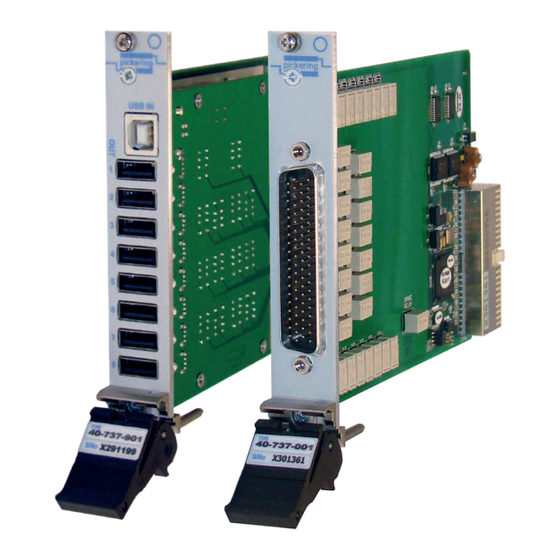
- Page 1 40-737 User Manual PXI USB Data Communications Multiplexer Module pickeringtest.com Issue 4.5 July 2021...
- Page 2 © COPYRIGHT (2021) PICKERING INTERFACES. ALL RIGHTS RESERVED. No part of this publication may be reproduced, transmitted, transcribed, translated or stored in any form, or by any means without the written permission of Pickering Interfaces. Technical details contained within this publication are subject to change without notice.
- Page 3 Pickering Interfaces strives to fulfil all relevant environmental laws and regulations and reduce wastes and releases to the environment. Pickering Interfaces aims to design and operate products in a way that protects the environment and the health and safety of its employees, customers and the public. Pickering Interfaces endeavours to develop and manufacture products that can be produced, distributed, used and recycled, or disposed of, in a safe and environmentally friendly manner.
-
Page 4: Product Safety
If this product is heavy reference should be made to the safety instructions for provisions of lifting and moving. STATIC SENSITIVE To indicate that static sensitive devices are present and handling precautions should be followed. REED RELAY MODULE 40-110/115/120/125 USB DATA COMMUNICATIONS MULTIPLEXER MODULE 40-737 Page (IV) Page (IV) -
Page 5: Table Of Contents
Section 5 Connector Information ..............5.1 Section 6 Trouble Shooting .................6.1 Section 7 Maintenance Information ............7.1 Switching System Test Tools ..........7.1 Relay Look-Up Table 8-Channel MUX ........7.2 Relay Look-Up Table 16-Channel MUX ........7.4 USB DATA COMMUNICATIONS MULTIPLEXER MODULE 40-737 Page (V) - Page 6 THIS PAGE INTENTIONALLY BLANK USB DATA COMMUNICATIONS MULTIPLEXER MODULE 40-737 Page (VI)
-
Page 7: Warnings And Cautions
Not to be used in safety critical circuits, refer to the Pickering Interfaces’ terms & conditions of sale. This module must not be used for the switching of Mains Circuits. For the switching of voltages up to the module’s full specification, Secondary Circuit power supplies and the Device Under Test must... - Page 8 • For suitably equipped products in the event of an emergency press the red “emergency stop” button situated on the front of the unit. USB DATA COMMUNICATIONS MULTIPLEXER MODULE 40-737 Page (VIII) 2 AMP 1-POLE UHD MATRIX MODULES 40-575 / 576 / 577 / 578 / 579...
-
Page 9: Technical Specification
Out4 Data In Data Out5 Data The 40-737 is an 8:1 or 16:1 multiplexer for switching data signals and is specifically designed for routing USB. The data paths are Out6 Data 2-pole differential pairs as defined by the USB standard. The... - Page 10 Out14 Vbus Out14 GND Out15 Data Out15 Vbus Out16 Data Out15 GND Out16 Vbus Out16 GND Switching diagram for the 40-737-001 16:1 USB Multiplexer, relays are shown in their default position. pickeringtest.com USB DATA COMMUNICATIONS MULTIPLEXER MODULE 40-737 Page 1.2...
- Page 11 * For full voltage rating, signal sources to be switched must be fully isolated from mains supply and safety earth. Power Requirements +3.3 V +5 V +12 V -12 V 0.05 A 0.5 A pickeringtest.com USB DATA COMMUNICATIONS MULTIPLEXER MODULE 40-737 Page 1.3...
- Page 12 The 40-965-909 interface board for Accessories. 16:1 USB switching applications For general purpose (non-differential) connection accessories for the 40-737 module please refer to the 90-006D 78-pin D-type connector data sheet where a complete list and documentation can be found for accessories, or refer to the Connection Solutions catalog.
- Page 13 We provide a full range of supporting cable and connector solutions for all our switching products—20 connector families with 1200+ products. We offer everything from simple mating connectors to complex cables assemblies and terminal blocks. All assemblies are manufactured by Pickering and are guaranteed to mechanically and electrically mate to our modules. Connectors & Backshells...
- Page 14 USB Data Comms MUX, 40-737 Programming Pickering provide kernel, IVI and VISA (NI & Keysight) drivers which are compatible with all Microsoft supported versions of Windows and popular older versions. For a list of all supporting operating systems, please see: pickeringtest.com/os...
-
Page 15: Functional Description
The default state of the multiplexer is as shown in Figures 2.2 and 2.3 overleaf. It should be noted; at power up, and following the clearing of the state of the subunits, that the data-paths default to channel 8 (40-737-901) or channel 16 (40-737-001) and the power-path defaults to an off state. - Page 16 Out5 GND RL13 Out6 Vbus Out6 GND RL14 Out7 Vbus Out7 GND RL15 Out8 Vbus Out8 GND Figure 2.2 - Switching Diagram For 40-737-901 USB 8:1 Multiplexer Module Showing Default Switch Positions USB DATA COMMUNICATIONS MULTIPLEXER MODULE 40-737 Page 2.2...
- Page 17 Out15 GND RL31 Out14 D- Out16 Vbus Out15 D+ Out16 GND Out16 D+ RL15 Out15 D- Out16 D- Figure 2.3 - Switching Diagram For 40-737-001 USB 16:1 Multiplexer Module Showing Default Switch Positions USB DATA COMMUNICATIONS MULTIPLEXER MODULE 40-737 Page 2.3...
- Page 18 SECTION 2 - TECHNICAL DESCRIPTION pickering THIS PAGE INTENTIONALLY BLANK USB DATA COMMUNICATIONS MULTIPLEXER MODULE 40-737 Page 2.4...
-
Page 19: Installation
Modular products require installation in a suitable PXI/LXI chassis. The module is designed for indoor use only. PREOPERATION CHECKS (UNPACKING) 1. Check the module for transport damage and report any damage immediately to Pickering Interfaces. Do not attempt to install the product if any damage is evident. -
Page 20: Hardware Installation
For a system comprising more than one chassis, turn ON the last chassis in the system followed by the penultimate, etc, and finally turn ON the external controller or chassis containing the system controller. 9. For Pickering Interfaces modular LXI installation there is no requirement to use any particular power up sequence. -
Page 21: Testing Operation
Figure 3.2 - General Soft Front Panel Icon A selector panel will appear, listing all installed Pickering PCI, PXI or LXI switch cards and resistor cards. Click on the card you wish to control, and a graphical control panel is presented allowing operation of the card. - Page 22 SECTION 3 - INSTALLATION pickering THIS PAGE INTENTIONALLY BLANK USB DATA COMMUNICATIONS MULTIPLEXER MODULE 40-737 Page 3.4...
-
Page 23: Programming Guide
SECTION 4 - PROGRAMMING Programming options for Pickering Interfaces PXI Modules For information on the installation and use of drivers and the programming of Pickering’s products in various software environments, please refer to the Software User Manual. This is available as a download from: https://www.pickeringtest.com/support/software-drivers-and-downloads... -
Page 24: 40-737 Card Architecture
Windows start menu. In addition programming ducumentation can be found on the DVD provided. Programming the 40-737 in C, C++ The following examples make the assumption that the 40-737 is in Bus 1, Slot 3 of a PXI or LXI chassis and on IP “192.168.1.11” (LXI examples only). - Page 25 SECTION 4 - PROGRAMMING GUIDE pickering Direct I/O Driver, Pilpxi Requires PilPxi.h and Pilpxi.lib usually found in the “\Pickering” folder structure on your disk. DWORD RetCode, Bus, Slot, CardNum, OutSub,BitNum; Bus= 1; Slot= 3; RetCode = PIL_OpenSpecifiedCard(Bus, Slot, &CardNum);//open the 40-737 card for use //preserving the MUX state RetCode = PIL_ClearCard(CardNum);...
- Page 26 //to the LXI Bus= 1; Slot= 3; RetCode = PIPLX_OpenSpecifiedCard(session, Bus, Slot, &CardNum); //open the 40-737 //card for use preserving the MUX state RetCode = PIPLX_ClearCard(session, CardNum);//clear all the sub units on the card - //will set the USB MUX to default channel 8 OutSub = 1;...
- Page 27 SECTION 4 - PROGRAMMING GUIDE pickering IVI Driver, pi40iv Requires pi40iv.h and pi40iv32.lib, ivi.lib usually found in the “\Pickering” or “\Program Files\IVI” folder structures on your disk. ViSession ViStatus RetCode = VI_SUCCESS; static ViRsrc rsrcName = “PXI1::3::INSTR”; //models PXI resource decriptor 1 & 3...
- Page 28 SECTION 4 - PROGRAMMING GUIDE pickering THIS PAGE INTENTIONALLY BLANK USB DATA COMMUNICATIONS MULTIPLEXER MODULE 40-737 Page 4.6...
-
Page 29: Connector Information
SECTION 5 - CONNECTOR INFORMATION The front panel connector layout for the 40-737-901 is shown in Figure 5.1 below. “USB IN” is a standard USB Type B connector, and the 1 to 8 “OUT” connectors are standard USB Type A connectors. - Page 30 Out16 Vbus Out16 D+ Out15 D+ Out15 GND Out16 GND Out16 D- Out15 D- FP_GND FP_GND Figure 5.2 - Pinouts: 16-Channel USB Multiplexer 40-737-001 (78-pin Male D-type Connector Viewed From Front of Module). USB DATA COMMUNICATIONS MULTIPLEXER MODULE 40-737 Page 5.2...
- Page 31 Channel 8 Channel 9 Channel 10 Channel 11 Channel 12 Channel 13 Channel 14 Channel 15 Channel 16 Figure 5.3 - Interface Board 40-965-909 For Use With 40-737-001 16-Channel USB Multiplexer: Connector Positions USB DATA COMMUNICATIONS MULTIPLEXER MODULE 40-737 Page 5.3...
- Page 32 SECTION 5 - CONNECTOR INFORMATION pickering THIS PAGE INTENTIONALLY BLANK USB DATA COMMUNICATIONS MULTIPLEXER MODULE 40-737 Page 5.4...
-
Page 33: Trouble Shooting
PCI configuration, highlighting any potential configuration problems. Specific details of all installed Pickering switch cards are included. All the installed Pickering switch cards should be listed in the “Pilpxi information” section - if one or more cards is missing it may be possible to determine the reason by referring to the PCI configuration dump contained in the report, but interpretation of this information is far from straightforward, and the best course is to contact Pickering support: support@pickeringtest.com, if possible... - Page 34 SECTION 6 - TROUBLE SHOOTING pickering THIS PAGE INTENTIONALLY BLANK USB DATA COMMUNICATIONS MULTIPLEXER MODULE 40-737 Page 6.2...
-
Page 35: Maintenance Information
For PXI modules which are supported in one of Pickering Interfaces’ Modular LXI Chassis (such as the 60-102B and 60-103B) no module software update is required. If the module was introduced after the LXI chassis was manufactured the module may not be recognized, in this case the chassis firmware may need upgrading. - Page 36 In D+ to Out7 D+ In Vbus to Out7 Vbus RL14 In D- to Out8 D- None Channel 8 Enabled In D+ to Out8 D+ None In Vbus to Out8 Vbus RL15 USB DATA COMMUNICATIONS MULTIPLEXER MODULE 40-737 Page 7.2...
- Page 37 SECTION 7 - MAINTENANCE INFORMATION pickering RL14 RL12 RL10 RL15 RL13 RL11 Figure 7.1 - 40-737-901 8-Channel USB Multiplexer Daughter Board Component Layout Showing Relay Positions USB DATA COMMUNICATIONS MULTIPLEXER MODULE 40-737 Page 7.3...
- Page 38 In D+ to Out15 D+ RL15 In Vbus to Out15 Vbus RL30 In D- to Out16 D- None Channel 16 Enabled In D+ to Out16 D+ None In Vbus to Out16 Vbus RL31 USB DATA COMMUNICATIONS MULTIPLEXER MODULE 40-737 Page 7.4...
- Page 39 SECTION 7 - MAINTENANCE INFORMATION pickering RL24 RL22 RL26 RL20 RL28 RL18 RL30 RL16 RL23 RL25 RL21 RL27 RL29 RL19 RL17 RL31 Figure 7.2 - 40-737-001 16-Channel USB Multiplexer Component Layout Showing Relay Positions USB DATA COMMUNICATIONS MULTIPLEXER MODULE 40-737 Page 7.5...
- Page 40 SECTION 7 - MAINTENANCE INFORMATION pickering THIS PAGE INTENTIONALLY BLANK USB DATA COMMUNICATIONS MULTIPLEXER MODULE 40-737 Page 7.6...
Need help?
Do you have a question about the 40-737 and is the answer not in the manual?
Questions and answers