
Related Manuals for Mitel MIVOICE OFFICE 400 415


Summary of Contents for Mitel MIVOICE OFFICE 400 415
- Page 1 MIVOICE OFFICE 400 MITEL 415/430 AS OF VERSION R6.1 SYSTEM MANUAL syd-0580_en / 2.1 – R6.1 – © 06.2019...
- Page 2 The information is subject to change without notice and should not be construed in any way as a commitment by Mitel or any of its affiliates or subsidiaries. Mitel and its affiliates and subsidiaries assume no responsibility for any errors or omissions in this document.
-
Page 3: Table Of Contents
Mitel Applications........ - Page 4 4. 2. 2. 2 Mitel 415 rack-mounting set ....... . 88 4.
- Page 5 IP system phones ........145 4. 8. 2 Mitel 6800/6900 SIP phone series......147 4. 8. 3 Standard SIP phones and standard SIP terminals .
- Page 6 5. 6. 6 Mitel 6800/6900 SIP phones ....... 178 Operation and Maintenance ....179 6.
- Page 7 Signal destinations ........230 Mitel 415/430...
- Page 8 Mitel DECT radio units ........251...
-
Page 9: Product And Safety Information
All user documents such as user guides and system manuals are available for download from the MiVoice Office 400 document portal as individual doc- uments or as documentation sets. Some user documents are accessible only via a partner login. Mitel 415/430 syd-0580/2.1 – R6.1 – 06.2019... -
Page 10: Safety Information
CAUTION! Caution indicates a potentially hazardous situation which, if not avoided, may result in minor or moderate injury and/or damage to the equipment or property. These symbols may appear on the product: Mitel 415/430 syd-0580/2.1 – R6.1 – 06.2019... - Page 11 A UPS system has to be connected up-circuit to ensure an uninter- ruptible power source. Up to a specific performance limit a Mitel 470 communication server can also be powered redundantly using an auxiliary power supply. For more in- formation please refer to your communication server's system manual.
-
Page 12: Data Protection
• Ensure the AC receptacle is installed near the equipment and easily accessible. • Use only Mitel approved power adapters. Any servicing, expansion or repair work is to be carried out only by trained technical personnel with the appropriate qualifications. -
Page 13: About This Document
Note In this document, it is presumed, that the Mitel SMB Controller is loaded with a MiVoice Office 400 application software. This assumption is always valid, even the expression Mitel SMB Controller, SMBC or communication server is used. - Page 14 Additional information on the handling or alternative operation of equipment. See also Reference to other chapters within the document or to other documents. Mitel Advanced Intelligent Network Particularities that have to be observed in an AIN. References to the MiVoice Office 400 configuration tool WebAdmin...
-
Page 15: System Overview
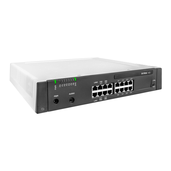
2. 2 Communication server The Mitel 415 and Mitel 430 communication servers are at the lower end of the MiVoice Office 400 family in terms of system capacity and expansion possibilities. However all MiVoice Office 400 communication servers are equipped with the same system software and offer the full scope of performance. -
Page 16: Installation Versions
2. 2. 1 Installation versions Mitel 415 and Mitel 430 are suitable for both desktop installation, wall mounting and in- stallation in a 19" rack. Covers for connecting cables and special installation covers for rack installation are available separately. -
Page 17: Positioning
System Overview 2. 2. 2 Positioning Applications range from very small offices and branches (Mitel 415) to small and me- dium-sized companies (Mitel 430). The diagram below shows the MiVoice Office 400 communication servers with their ex- pansion capacity for users with SIP/IP phones and TDM extensions (FXS, DSI, BRI-S). -
Page 18: Mitel System Phones And Clients
MiVoice Office 400 communication platforms can be used to network up to 100 other Mitel sys- tems or SIP-compatible third-party systems. All the main telephony features such as call number and name display, enquiry call, hold, brokering, call transfer and confer- ence circuits are supported. - Page 19 • Headset port convertible to • Support for optional cordless DHSG/EHS capable headset port speech optimized handset Mitel 6940 • Excellent voice quality due to Mitel • Magnetic keyboard connector SIP Phone Hi-Q™ wideband audio technology • Can be used as auxiliary reception •...
- Page 20 Note: The phones of the Mitel 6700 SIP series (Mitel 6730 SIP, Mitel 6731 SIP, Mitel 6735 SIP , Mitel 6737 SIP , Mitel 6739 SIP, Mitel 6753 SIP, Mitel 6755 SIP and Mitel 6757 SIP) are supported as before (not all system features can be used).
- Page 21 System Overview Tab. 3 SIP Multimedia Terminal Mitel BluStar 8000i Product Main features • Intelligent multimedia terminal with intuitive operation • Video conferencing solution, collaboration tool and application platform in one. • XML browser compatible • Bluetooth interface • Can be connected to a laptop •...
- Page 22 • All the system features can be used • FMC client for mobile phones (runs on various operating systems) • Integrates the mobile phone into the Mitel communication system • User is always reachable under the same call number (One Number con-...
- Page 23 (can be used with Mitel SIP-DECT only). Note: The Mitel 610 DECT, Mitel 620 DECT, Mitel 630 DECT, Office 135/135pro and Office 160pro/Safeguard/ATEX cordless system phones are supported as before (not all system features can be used). Mitel 415/430...
-
Page 24: Various Phones, Terminals And Equipment
The Aastra 1910 and Aastra 1930 analogue phones are still supported. 2. 5 Various phones, terminals and equipment Thanks to the use of international standards other clients, terminals and phones, Mitel and third-party, can be connected and operated on the communication server: • SIP-based phones... -
Page 25: Solutions
The func- tions are operated using the Mitel 6940 SIP, Mitel 6873 SIP, MiVoice 5380 / 5380 IP reception phone or the web-based Mitel 400 Hospitality Manager application. Re- duced hospitality functionality are also available on Mitel 6920 SIP, Mitel 6930 SIP, Mitel 6867 SIP and Mitel 6869 SIP phones. -
Page 26: Applications And Application Interfaces
System Overview The Mitel application Mitel Open Interfaces Platform (OIP), as well as the certified third-party applications, are installed on a customer server. They communicate with the communication server via standardised interfaces (see "Application interfaces", page 28). Auxiliary applications for planning and the configuration and park management are available as a web application. - Page 27 System Overview Application Main features • Mitel 400 CCS is an additional application for the Mitel 400 Call Center, and Mitel 400 CCS provides statistics / reporting functions and agent monitoring (CCS = call centre supervision). The licensing of the application is made via OIP.
-
Page 28: Application Interfaces
Application interfaces The most important interface for own and third-party applications is the interface of the Mitel Open Interfaces Platform (OIP). This open interface allows the applications to be deeply integrated with telephony. Third-party applications can also be integrated on MiVoice Office 400 series systems via different interfaces without OIP. -
Page 29: Mitel Open Interfaces Platform
Sophisticated Softphones are available as OIP applications and are controlled as cli- ents via OIP. • Mitel OfficeSuite is a rich-client application, which significantly broadens the range of functions of the coupled fixed and cordless phones. • MiVoice 1560 PC Operator is an operator application which can be used as rich-cli- ent application together with a fixed or cordless phone or alone as Softphone. - Page 30 OIP as call center The powerful Mitel 400 Call Center is an integral part of OIP and provides all the main features such as flexible routing algorithms (cyclical, linear, longest time available, CLIP-based, last agent), skill-based agent groups as well as an analysis of the call centre data (online and offline) with chart-based evaluation.
-
Page 31: Message And Alarm Systems
PC operator console for all the users connected. See also: More information can be found in the Mitel Open Interfaces Platform system manual and in the OIP WebAdminOnline help. 2. 7. 2. 2... -
Page 32: Cti - Computer Telephony Integration
The Mitel Alarm Server is a flexible solution which can be used in all sectors to process and record alarms. It can be used, for instance, in old people's nursing homes and as- sisted-living homes, as well as in other different facilities such as hotels, industrial plants, shopping centres, schools or administrations. -
Page 33: Isdn Interface
In addition phones on ISDN and analogue interfaces can also be monitored. PC and phone allocation is handled by the telephony server. The third-party CTI connection is effected via Ethernet using the Mitel Open Interfaces Platform (OIP). To this end the OIP is installed on the telephony server. Third-party connections via Ethernet with CSTA are also possible. -
Page 34: Configuration
Configuration is done through WebAdmin. The Mitel 6940 SIP, Mitel 6873 SIP, MiVoice 5380 / 5380 IP reception phone or the web-based Mitel 400 Hospitality Man- ager application is available to operate the functions. Reduced hospitality functionality are also available on Mitel 6920 SIP, Mitel 6930 SIP, Mitel 6867 SIP and Mitel 6869 SIP phones. -
Page 35: Connection Options
Third-Party CTI with telephony server Special interfaces CTI /call centre workstations Door intercom system Door opener Fixed Mobile Convergence Controller Mitel Mobile Client Bell input Ethernet Applications server Audio source (input) Open Interfaces Platform (OIP) Ethernet Telephony Web Interface (TWP) -
Page 36: Getting Started
Required accesses The URL’s listed below refer to proprietary Mitel sites. You need a partner login to ac- cess them. If you do not have a Mitel partner login, ask your sales partner for more in- formation. Tab. 11... -
Page 37: Download Documents, System Software And Tools
System Overview Mitel CPQ is designed to support you with the different activities in the sales and order- ing process. It is a web-based application for online usage. You can access the appli- cation through the Mitel Connect Portal [2]. -
Page 38: Put Into Operation
3. Connect the earthing wire on the ground terminal of the bottom plate. 4. Assemble interface cards (if any): – Fit interface cards into the IC1...IC2 slots (Mitel 415) or into the IC1...IC4 slots (Mitel 430). – Fit the corresponding wiring adapters WA2 WA3 WA4 into the to WA1...WA2 sockets... - Page 39 These texts are stored in audio files. You can download audio guide lan- guages through the menu Localize System Search and then upload them to the communication server in this view. Mitel 415/430 syd-0580/2.1 – R6.1 – 06.2019...
- Page 40 – Copy the Equipment ID (EID) to the clipboard. – In a new browser window, log in to the Mitel Connect portal [2] and open the cences & Services section. – Option 1: If you have a voucher, enter the voucher number in the...
-
Page 41: Register And Connect The Phones
System Overview Note If you do not set these parameters, you cannot load audio guides or update Mitel SIP phone strings from the Mitel download server. 3. Click Apply and Next. The third page, Configuring media resources, opens. On this page, the system proposes to configure the DSP resources automatically. - Page 42 System Overview Register a Mitel SIP phone 1. Go to Terminals Standard terminals =qd) in WebAdmin and click the phone you want to register with the communication server. The automatically generated SIP credentials and registration credentials (Registra- tion user name Registration password) of the phone are displayed.
-
Page 43: Make Further Configurations
For further configurations, use the WebAdmin configuration assistant and the online help. For detailed information, see the user’s guides and system manuals (part of the Documentation set). Mitel 415/430 syd-0580/2.1 – R6.1 – 06.2019... -
Page 44: Expansion Stages And System Capacity
3. 1 Summary The expansion possibilities of the basic systems Mitel 415 and Mitel 430 at a glance. The equipment is powered by an external power supply. The same power supply unit is used for Mitel 415 and Mitel 430. -
Page 45: Basic System
3. 2 Basic system Mitel 415and Mitel 430 are based on the same basic system, they differ in terms of the components fitted to the mainboard, the expansion possibilities and the system capac- ities. The basic systems consists of the following components: •... - Page 46 Slot for stackable system modules, type 1 (DSP(X) modules) Slot for stackable system modules, type 2 (not used for the moment) Fig. 7 Mainboard interfaces, display and control elements and front panel Mitel 415/430 syd-0580/2.1 – R6.1 – 06.2019...
-
Page 47: Power Supply
Tab. 14 Fixed functions of the mainboard DSP Max. number of simultaneous ... Mitel 415 Mitel 430 Total circuits for the functions three-party conference, six-party conference, intrusion and silent intrusion. - Page 48 DSP. – The system has to be restarted for the configuration changes of the DSP to take effect. Mitel 415/430 syd-0580/2.1 – R6.1 – 06.2019...
-
Page 49: Expansion With Cards And Modules
Fitting DSP modules on the SM2 slot is thus not mechanically possible. Tab. 16 DSP modules Number of DSP chips Max. number of Max. number of Type per module Mitel 415 modules Mitel 430 modules SM-DSPX1 SM-DSPX2 SM-DSP1 SM-DSP2 1) Although no longer available, the module is still supported. Mitel 415/430... - Page 50 For reliable real-time fax transmissions via an IP network using the T.38 fax protocol (ITU-T). FoIP channels can be used without a licence. • Audio services The audio channels are used to play back and record audio data. Additionally, each Mitel 415/430 syd-0580/2.1 – R6.1 – 06.2019...
- Page 51 VoIP channels are always required between IP and non-IP endpoints. They are freely available, i.e. they are always used wherever they happen to be needed. The figure below gives an overview of the cases where VoIP channels are needed and how many of them. Mitel 415/430 syd-0580/2.1 – R6.1 – 06.2019...
- Page 52 Non-IP endpoints: IP endpoints • Analogue terminal (FXS) • IP system phone • Digital system terminal (DSI) • Mitel SIP terminal • DECT cordless phone (DSI) • Standard SIP terminal • ISDN phone (BRI-S) • DECT cordless phone via SIP-DECT •...
- Page 53 No audio channels can be reserved for conference bridges. Audio channels from the Non-reserved/shared pool are always used for the conference bridge. Announcement service and music on hold use their own resources. Mitel 415/430 syd-0580/2.1 – R6.1 – 06.2019...
- Page 54 Play Channels licence. Configuration of DSP chips The functions which can be allocated to each DSP chip are determined in the Media resources =ym) view. The DSP modules provide additional functions as indicated in Mitel 415/430 syd-0580/2.1 – R6.1 – 06.2019...
- Page 55 Only for VoIP mode G.711 G.711/G.729 Only for VoIP mode G.711 G.711/G.729 1 channel for Mitel 415 2 channels for Mitel 430 Only if Voice mail mode Expanded (G.729 only) Only if Voice mail mode Expanded (G.729 only) 1) Licence(s) required (see also "Licences", page 67).
-
Page 56: Interface Cards
The interfaces are routed to the front panel using the wiring adapters (see "Wiring adapter", page 59). The length varies depending on the type of interface card. For precise dimensions see the Chapter "Technical data", page 245. Mitel 415/430 syd-0580/2.1 – R6.1 – 06.2019... -
Page 57: Trunk Cards
2 × FXO TIC-2AB 2 × FXO EAAB2 1) Cards with hardware version "-2" only. The ESST-1 card is not operational in Mitel 415/430. 2) Although no longer available, the card is still supported. Mitel 415/430 syd-0580/2.1 – R6.1 – 06.2019... -
Page 58: Terminal Cards
T. 1) Although no longer available, the card is still supported. 2) Cards with hardware version "-2" only. The ESST-1 card is not operational in Mitel 415/430. Note On the ESST terminal card the jumper must always be fitted in position T (see Fig. 24). -
Page 59: Options Card
Note If the options card is used to connect a door intercom, it must be fitted to slot IC2 (Mitel 415) or slot IC4 (Mitel 430). This means that only one options card can be used for this purpose on each communication server. -
Page 60: System Capacity
Mainboard interfaces, TIC-4AB, TIC-2AB, Included in the equipment supplied with TIC- ETAB4, EAAB2, EADP4, EAD4C, EAD4V 4AB, TIC-2AB, ETAB4 and EADP4 (with ETAB4 and EADP4 only with order variant Mitel 415/430). WA-1PRI TIC-1PRI Included in the equipment supplied with the interface card 1) On the ESST terminal card the jumper must always be fitted in position T (see Fig. -
Page 61: Media Resources
Tab. 27 General system capacity AIN with Max. number... Mitel 415 Mitel 430 Mitel 430 as Master Nodes in a transparent network (AIN) – – Nodes with SIP networking Users Terminals per user Simultaneous connections •... - Page 62 1500 1500 1500 Operator keys per phone on Mitel 6800/6900 SIP Room keys on Mitel 6873 SIP (inclusive expansion keypad) Line keys per key telephone (except Mitel 6800/6900 SIP) Line keys per key telephone on Mitel 6800/6900 SIP 2...12 2...12 2...12...
- Page 63 2) Up to 100 users are possible with virtual terminals and integrated mobile/external phones. 3) Only 1 operator console, 1 MiVoice 2380 IP, 1 BluStar 8000i , 1 Mitel BluStar for PC, 1 Mitel SIP-DECT, 2 DECT-cordless phones and 1 MiCollab client (3 MiCollab clients with MiCollab version 8.1) are possible for each user.
-
Page 64: Terminals
/ total line keys): (8/24), (7/28), (6/36), (5/50), (4/60), (3/60), (2/60), (1/60). Example: The following line keys are configured on different Mitel SIP phones: 4 keys for line 1, 7 keys for line 2, 5 keys for line 3, 5 keys for line 4. - Page 65 Mitel 6930 SIP Mitel 6940 SIP Mitel 6863 SIP Mitel 6865 SIP Mitel 6867 SIP Mitel 6869 SIP Mitel 6873 SIP Mitel SIP-DECT Cordless phones Standard SIP terminals Mitel BluStar 8000i Mitel BluStar Softphones Mitel Mobile Client Controller – Virtual terminals –...
-
Page 66: Terminal And Network Interfaces
Terminal and network interfaces Tab. 29 Terminal and network interfaces AIN with Max. number... Mitel 415 Mitel 430 Mitel 430 as Master Ethernet interfaces per node Network interfaces, total (FXO, BRI-T, PRI, BRI-S ext. Terminal interfaces, total (DSI, FXS, BRI-S) -
Page 67: Software Assurance
The Mitel CPQ application automatically plans the nec- essary licences, which are then enabled on the communication server using a licence file. - Page 68 Note: The purchase of a new communication server also includes a software assurance for a spe- cific period. Log on with your partner login to Mitel Connect https://connect.mitel.com obtain a new licence file using the EID number and the voucher. The licence file issued as a...
- Page 69 Mitel SIP-DECT or Mitel SIP WLAN base stations, one licence is required per terminal or user. The licences are needed when registering the termi- nals or the user on the system. If the licences are missing, Mitel SIP terminals can also be operated with...
- Page 70 MMC Extension With this licence mobile phones can be integrated into the communication system together with an Mitel Mobile Client Controller, Mitel Mobile Client, and MiVoice Of- fice Mobile Application client. The MMC Controller allows mobile users to move back and forth between the internal WLAN coverage and the mobile radio network without the call being interrupted.
- Page 71 Enterprise Voice Mail licence. Mitel Advanced Intelligent Network In an AIN the Enterprise Voice Mail and Audio Record & Play Channels licences are all acquired for the Master. The number of Audio Record & Play Channels licences determines the maximum number of simultaneously active audio channels, regardless of the nodes on which they are currently being used.
- Page 72 In an AIN the licence is always acquired on the Master. The licence allows the remote main- tenance of the AIN via any Mitel 415/430 node. Note: The master node can also be of Mitel SMBC, Mitel 470 or Virtual Appliance type. •...
- Page 73 If Virtual Appliance is used as Master, the VoIP channels of the master node are made avail- able without a licence from the integrated Mitel Media Server. However, for the satellites' VoIP channels, the licences must be purchased. Networking •...
- Page 74 PC dial help) for a specific number of users (see "General system capacity", page 61). It cannot be combined with CTI third-party licences. • Dialers This licence allows you to use the Mitel Dialer CTI application. The number of li- cences determines the simultaneously active, user-assigned Mitel Dialer applica- tions. •...
- Page 75 Note: If you use the Mitel Open Interfaces Platform, OIP takes the licences from the communica- tion server. So always acquire these licences for the communication server so you can use ATAS even without OIP.
-
Page 76: Restricted Operating Mode
• Call centre functions are out of service (no routing to ACD). • Voice mail functions are out of service (no call routing to voice mail). • The announcement service is out of service. Mitel 415/430 syd-0580/2.1 – R6.1 – 06.2019... -
Page 77: Temporary Offline Licences
Basic User Licence bundle: 1 additional user per In the AIN, ✓ – 1 additional user licence. only on the 1 phone licence (any one) Master; 1 phone per user only otherwise per node. Mitel 415/430 syd-0580/2.1 – R6.1 – 06.2019... - Page 78 In the AIN, Phones MiVoice 5360 IP, IP system phones per only on the MiVoice 5361 IP, licence Master; MiVoice 5370 IP and otherwise MiVoice 5380 IP IP sys- per node. tem phones Mitel 415/430 syd-0580/2.1 – R6.1 – 06.2019...
- Page 79 ✓ ✓ Mitel 8000i Video Use of the video function- Additional licence for In the AIN, Options ality of an Mitel SIP termi- Mitel SIP Terminals. 1, only on the 20 or 50 additional Master; Mitel SIP terminals otherwise with video functionality per node.
- Page 80 Features ✓ ✓ Analogue Modem Use of the modem func- Locked Enabled In the AIN, tionality on an only on the Mitel 415/430. Master; otherwise per node. Secure VoIP Encrypted VoIP connec- Non- Encrypted transmis- Per node – –...
- Page 81 QSIG Networking QSIG channels Per licence 4 or n Per node Channels QSIG channels (n lim- ited by the system capacity) Base Mitel AIN Operation of an AIN Locked AIN with master and Only on the – – one satellite...
- Page 82 – ously active, user-linked instances per licence only on the Mitel Dialer applications. Master; otherwise per node. ✓ Hospitality Manager Use of Mitel 400 Hospital- Locked Enabled In the AIN, – ity Manager only on the Master; otherwise per node.
- Page 83 Licences Trial Licence Licensed attributes With licence for net- licenc licenc licence working ✓ ✓ Mitel OpenCount Additional licence: Offers Locked Enabled In the AIN, Functional Upgrade extra functions such as only on the to Comfort PIN telephony. Master; otherwise per node.
-
Page 84: Power Supply Capacity
3) If Virtual Appliance is used as Master, the VoIP channels of the master node are made available without a li- cence from the integrated Mitel Media Server. However, for the satellites' VoIP channels, the licences must be purchased. -
Page 85: Supply Power Available For Terminals
Expansion key module MiVoice M530 MiVoice 5380 Expansion key module MiVoice M535 MiVoice 5370, MiVoice 5380 Radio unit without power supply unit SB-4+ DSI-AD2 interface 1500 Radio unit without power supply unit SB-8 2 DSI-AD2 interfaces 1350 Mitel 415/430 syd-0580/2.1 – R6.1 – 06.2019... -
Page 86: Power Supply Per Terminal Interface
4) The value applies to each interface and to radio units with hardware version "-2". The value per interface for radio units with hardware version "-1" is 150 mW lower. 5) The value depends greatly on the terminal type. With the planning application Mitel CPQ the power supply available for terminals is checked automatically. Overload shut-down If the rated power is exceeded the power supply is disconnected. -
Page 87: Installation
Installation Installation This Chapter tells you how Mitel 415/430 can be installed and the conditions to be observed. It also includes the mounting into a 19” rack, the correct way to connect the earthing, and the power supply. Other topics described in this chapter comprise fitting with system modules, interface cards and the relevant wiring adapters. -
Page 88: Equipment Supplied
• Product information 4. 2. 2 Mounting options Mitel 415/430 includes all the materials required for wall or desktop installation. Addi- tional rack installation sets are required for a 19” rack installation. These sets for Mitel 415 and Mitel 430 are different. -
Page 89: Location Requirements
• In a rack-mounted installation the space to the left and right between the communication server and the wall of the 19” rack must remain empty. • The installation of a fan is also mandatory for the Mitel 430. Environment •... -
Page 90: Wall Mounting
The two diagrams below illustrate the two wall-mounting possibilities. All dimensions in mm Fig. 12 Minimum distances for wall mounting (front panel facing to the right) Mitel 415/430 syd-0580/2.1 – R6.1 – 06.2019... -
Page 91: Drilling Plan
A or B on the drilling plan. The communi- cation server is secured with a third screw to prevent it from being dislodged acciden- tally (position C). Mitel 415/430 syd-0580/2.1 – R6.1 – 06.2019... -
Page 92: Drilling Template
The packaging box of the communication server can also be used for marking out the drill holes. To do so it is best to detach the part of the inner packaging box that contains the drill holes. Note: The holes on the cardboard box are not labelled. Mitel 415/430 syd-0580/2.1 – R6.1 – 06.2019... -
Page 93: Wall-Mounting Procedure
Make sure you observe the minimum distances to other objects, walls or ceil- ings as shown in Fig. 12 and Fig. 13. 2. Drill the three dowel holes. 3. Insert the dowel plugs. Mitel 415/430 syd-0580/2.1 – R6.1 – 06.2019... -
Page 94: Desktop Installation
• The holes in the mounting plates allow two communication servers to be placed di- rectly above each other with a space requirement of three units. Different holes in the mounting plates are used for this purpose (see Fig. 16). Mitel 415/430 syd-0580/2.1 – R6.1 – 06.2019... -
Page 95: Rack-Mounting Procedure
• The space on the left and right between the communication server and the panels of the 19” rack is for heat dissipation and must remain clear. • The installation of a fan is mandatory whenever an Mitel 430 is rack-mounted; the fan is included in the Mitel 430 rack-mounting kit. -
Page 96: Installing The Fan
Installing the fan Materials required: • Fan from the Mitel 430 rack-mounting kit • 2 screws from the Mitel 430 rack-mounting set • Screwdriver To install the fan proceed as follows: 1. Shut down the communication server (see "Shut-down Mode", page 203) and dis- connect it from the power supply. -
Page 97: Installing The Cable Cover
6. Reconnect the communication server to the power supply. Note The fan only turns if required by the equipment temperature. Fig. 17 Installing the fan in Mitel 430 4. 2. 7. 3 Installing the cable cover Materials required: • Cable cover set •... -
Page 98: Earthing And Protecting The Communication Server
The serrated lock washer must rest against the metal housing of the communication server. Mitel 415/430 syd-0580/2.1 – R6.1 – 06.2019... - Page 99 2,5 mm2 protected 4,0 2,5 mm2 protected 4,0 Building earth Building earth mm2 unprotected mm2 unprotected Fig. 20 Earthing of the communication server in the case of an indirect cabling and direct cabling Mitel 415/430 syd-0580/2.1 – R6.1 – 06.2019...
-
Page 100: Connecting The Cable Screening
4. 4. 1 115/230 V power supply The communication server is powered by the supplied power supply unit. The power supply unit is connected to the mains using a two-pin standard power cable. Mitel 415/430 syd-0580/2.1 – R6.1 – 06.2019... -
Page 101: Uninterruptible Power Supply (Ups)
Tab. 34 Maximum power requirements of the communication server Communication server Maximum power requirements Mitel 415 100 VA Mitel 430 150 VA The battery capacity required [Ah] can be calculated using the battery voltage and the maximum bridging time. -
Page 102: Equipping The Basic System
4. 5. 1 Fitting an interface card Interface cards are fitted to slots IC1…IC4. IC3 and IC4 can be found only on the Mitel 430 (see Fig. 7). CAUTION! Be sure to observe the "Safety regulations", page 89. 1. Shut down the communication server (see "Shut-down Mode", page 203) and dis- connect it from the power supply. -
Page 103: Fitting A Wiring Adapter
Fitting an interface card Notes – The ODAB options card must be fitted to slot IC2 (Mitel 415) or slot IC4 (Mitel 430) if it is to be used for connecting a door intercom (see "Equipment on the ODAB options card", page 136). - Page 104 2) On the ESST terminal card the jumper must always be fitted in position T (see Fig. 24). 3) The wiring adapter is only part of the equipment supplied with order variant Mitel 415/430. 4) For test purposes the PRI interface is also routed in parallel to port X.2.
-
Page 105: Fitting Dsp Modules
Mitel 430 due to their mechanical dimensions. – If the ODAB options card is used to connect a door intercom, it must be fitted to slot IC2 (Mitel 415) or slot IC4 (Mitel 430). Mitel 415/430 syd-0580/2.1 – R6.1 – 06.2019... -
Page 106: Connecting The Communication Server
– If the ODAB options card is used to control switch group positions and external devices, it must be fitted to slot IC1 (Mitel 415) or slot IC1, 2 or 3 (Mitel 430). • DSP modules are stackable and must always be fitted to slot SM1. Slot SM2 on the Mitel 430 communication server is not supported. -
Page 107: Direct Connection
• 2 network interfaces BRI-T or 2 terminal interfaces BRI-S or a combination thereof. • 10 terminal interfaces (DSI, FXS) or a combination thereof. 1)Not valid for USA/Canada. Mitel 415/430 syd-0580/2.1 – R6.1 – 06.2019... - Page 108 – violet – white – brown – turquoise – violet – white – grey – turquoise – violet – – blue – turquoise – violet – – orange – turquoise – violet – Mitel 415/430 syd-0580/2.1 – R6.1 – 06.2019...
-
Page 109: Connection To A Universal Building Cable Installation (Ubc)
Patch panel User 2nd floor Phone User 1st floor Communi- cation Phone server User Ground floor Phone (Main) distri- bution frame Fig. 28 Connecting to a UBC via a (main) distribution board (example) Mitel 415/430 syd-0580/2.1 – R6.1 – 06.2019... -
Page 110: Cabling Interfaces
A port address is always of the type x.y. (x is the number of the card slot, and y, the port number.) The slot numbering begins with 0 (=mainboard) and ends with 2 (for Mitel 415) or 4 (for Mitel 430). -
Page 111: Network Interfaces
Basic rate interface BRI-T With the appropriate interface cards and wiring adapters, BRI network interfaces can be made available at RJ45 sockets 1.x...4.x (for Mitel 415 1.x and 2.x only). The possi- ble RJ45 sockets are highlighted in colour in the figure below. - Page 112 Tab. 39 Wiring of the BRI basic rate interface network-side Cable cores Communication server Straight patch cable BRI-T sig- BRI-T sig- Socket Socket – – – – – – – – Mitel 415/430 syd-0580/2.1 – R6.1 – 06.2019...
- Page 113 PINX1 signal, PINX 2 signal, basic rate inter- Cable cores Network Cable cores basic rate inter- face BRI-T face BRI-T See also Chapter "Connections with basic accesses" in the PISN/QSIG Networking System Manual. Mitel 415/430 syd-0580/2.1 – R6.1 – 06.2019...
-
Page 114: Primary Rate Interface Pri
With the appropriate interface cards and wiring adapters, PRI network interfaces can be made available at RJ45 sockets 1.1, 2.1, 3.1 and 4.1 (Mitel 415 only 1.1, 2.1). For test purposes the PRI interface is also routed in parallel to ports x.2. The possible RJ45 sockets are highlighted in colour in the figure below. - Page 115 Primary rate access in the private leased-line network 4-wire Copper line PINX 1 PINX 2 max. 200 m 4-wire Copper line PINX 1 PINX 2 max. 200 m Fig. 37 Primary rate access, networked with copper line Mitel 415/430 syd-0580/2.1 – R6.1 – 06.2019...
- Page 116 Crossed patch cable signal — — — — — — — — Transmission facilities PINX 1 PINX 2 max. max. 200 m 200 m Fig. 38 Primary rate interface, networked with transmission equipment Mitel 415/430 syd-0580/2.1 – R6.1 – 06.2019...
- Page 117 — — — — — — — — Leased-line or dial-up PINX 1 PINX 2 connection Mains power Mains power Fig. 39 Primary rate access PRI, networked with leased-line or dial-up connection Mitel 415/430 syd-0580/2.1 – R6.1 – 06.2019...
-
Page 118: Fxo Network Interfaces
With the appropriate interface cards and wiring adapters, FXO network interfaces can be made available at RJ45 sockets 1.x...4.x (for Mitel 415 only 1.x and 2.x) The possi- ble RJ45 sockets are highlighted in colour in the figure below. The maximum number of interfaces per communication server has to be taken into account (see Tab. -
Page 119: Terminal Interfaces
4. 7. 3. 1 DSI terminal interfaces The DSI terminal interfaces of the mainboard (for Mitel 415 only 0.5 and 0.6) are per- manently routed to the front panel and labelled accordingly. With the appropriate inter- face cards and wiring adapters, additional DSI terminal interfaces can also be made available at the RJ45 sockets 1.x...4.x (with Mitel 415 only 1.x and 2.x). - Page 120 DSI-AD2 bus length and number of phones Distance between the 1st and 2nd connection Number of phones Total length of DSI-AD2 bus point (without connection cable) A: max. 1200 m – B: max. 1200 m C: max. 10 m Mitel 415/430 syd-0580/2.1 – R6.1 – 06.2019...
- Page 121 DECT radio unit without power supply unit SB-4+ DSI-AD2 interface 1700 DECT radio unit without power supply unit SB-8 2 DSI-AD2 interfaces 1550 DECT radio unit with power supply unit SB-4+/SB-8 1 or 2 DSI-AD2 interfaces < 100 Mitel 415/430 syd-0580/2.1 – R6.1 – 06.2019...
- Page 122 • Applies to the SB-4+/SB-8 DECT radio units with hardware version "-2" if they are not connected to a basic system with hardware version "-2" or are not connected to an EADP4 interface card with hardware version "-3". Mitel 415/430 syd-0580/2.1 – R6.1 – 06.2019...
- Page 123 Applies to the SB-4+/SB-8 DECT radio units with hardware version "-2" if they are con- nected to a basic system with hardware version "-2" or to an EADP4 interface card with hardware version "-3". Mitel 415/430 syd-0580/2.1 – R6.1 – 06.2019...
- Page 124 The maximum power available is also determined based on the calculated line length (assumption: Diameter = 0.5 mm). If the calculated power available is below the maximum possible power input of the connected system phones, the message Mitel 415/430 syd-0580/2.1 – R6.1 – 06.2019...
- Page 125 • Maximum line length for a wire diameter of 0,6 mm: 1170 m Example 3: Evaluation of an existing line installation Line diameter: 0.5 mm Loop resistance: 120 Ω Fig. 43 indicates: • Line length: 660 m • Power available: 2120 mW Mitel 415/430 syd-0580/2.1 – R6.1 – 06.2019...
-
Page 126: Bri-S Terminal Interfaces
(CH: Applies also to cable type G51) Installation rules • If an Mitel DECT radio unit is used, do not connect any other system phone to the same DSI bus. • Do not use any terminating resistors at the bus extremity. - Page 127 Short, V-shaped Long Point-to-point Length (max.) Server ↔ terminal 2 × 150 m 150 m 500 m 1’000 m Terminal 1 ↔ Terminal 4 – – 20 m – Number of terminals (max.) Mitel 415/430 syd-0580/2.1 – R6.1 – 06.2019...
- Page 128 2 x 100 Ω tion server max. 20 m max. 500 m Fig. 48 S bus, long Connection point Communi- cation 2 x 100 Ω server max. 1000 m Fig. 49 S bus, point-to-point Mitel 415/430 syd-0580/2.1 – R6.1 – 06.2019...
- Page 129 The number of terminals is the sum of the power requirements of the individual termi- nals and the power available on the S bus. Connection sockets RJ45, 8-pin Front view of RJ45 Fit resistors at bus extremity only Fig. 50 RJ45 connection, single socket Mitel 415/430 syd-0580/2.1 – R6.1 – 06.2019...
- Page 130 < 125 Ω (100 kHz), < 115 Ω (1 MHz) Characteristic impedance Wave attenuation < 6 dB/km (100 kHz), < 26 dB/km (1 MHz) Near/crosstalk attenuation > 54 dB/100 m (1 kHz to 1 MHz) Mitel 415/430 syd-0580/2.1 – R6.1 – 06.2019...
-
Page 131: Fxs Terminal Interfaces
With the appropriate interface cards and wiring adapt- ers, additional FXS terminal interfaces can also be made available at the RJ45 sockets 1.x...4.x (with Mitel 415 only 1.x and 2.x). The possible RJ45 sockets are highlighted in colour in the figure below. - Page 132 Circuit type as per EN/IEC 60950: TNV-2 FXS mode: Phone/fax In this mode the following analogue terminals can be connected: • Analogue phones with DTMF or pulse dialling (earth key is not supported) Mitel 415/430 syd-0580/2.1 – R6.1 – 06.2019...
- Page 133 24 VDC. The loop current is limited to 25 mA. 1) Transmission with the T.38 protocol is recommended for Fax over IP. The corresponding media re- sources need to be allocated. Mitel 415/430 syd-0580/2.1 – R6.1 – 06.2019...
- Page 134 FXS interface The diode is necessary, in order to avoid unwanted voltages at the control output during the the start-up phase of the communication server. Fig. 55 Connection for FXS mode: Control output Mitel 415/430 syd-0580/2.1 – R6.1 – 06.2019...
- Page 135 2 control inputs which switch the switch position of the switch group depending on the status. Tab. 61 Switch group control via the control inputs FXS control input 1 FXS control input 2 Switch positions of the switch group Position 1 Position 2 Position 3 Mitel 415/430 syd-0580/2.1 – R6.1 – 06.2019...
-
Page 136: Equipment On The Odab Options Card
The ODAB options card contains the following equipment: • 1 analogue terminal interface for connecting a door intercom • Control outputs and control inputs for connecting a door intercom and/or other pur- poses. Mitel 415/430 syd-0580/2.1 – R6.1 – 06.2019... -
Page 137: Connection Of A Door Intercom (Tfe)
2.1...2.3 (Mitel 415) and 4.1...4.3 (Mitel 430). • If the option card is used for other purposes, it must be fitted to slot IC1 (Mitel 415) and IC1...3 (Mitel 430). The RJ45 socket x.1 then provides two control outputs and the RJ45 socket x.2 two control inputs. - Page 138 Jumper configuration for connecting a door intercom Note If the options card is fitted on slot IC2 (Mitel 415 or slot IC4 (Mitel 430), the jumpers of Ports 1, 2 and 3 must be fitted as shown in Fig. 59.
- Page 139 • The bell key switch does not require an external power supply, but must have a floating connection. • Component damage due to double power supply: If the voice path is powered via the door intercom, it should not be connected to Ta’ and Tb’. Mitel 415/430 syd-0580/2.1 – R6.1 – 06.2019...
-
Page 140: Control Outputs And Control Inputs
Jumper configuration for control outputs and control inputs Note If the options card is fitted in slot IC1 (Mitel 415) or slot IC1, 2 or 3 (Mitel 430), the jumpers must be fitted as shown in Fig. 61. Mitel 415/430... - Page 141 Installation Tab. 65 Connection in slot IC1 (Mitel 415) or slot IC1, 2 or 3 (Mitel 430) Communication Communication RJ45 RJ45 server server Socket X1 Signal Socket X3 Signal – – – – O1-1 – O2-1 – O2-2 – O1-2 –...
-
Page 142: Audio Interface
Any playback equipment (tape recorder, CD player, etc.) with a line output can be used as the audio source. The customer is responsible for all copyright matters relating to any music playback. Mitel 415/430 syd-0580/2.1 – R6.1 – 06.2019... -
Page 143: Ethernet Interfaces
4. 7. 6 Ethernet interfaces The Mitel 415/430 communication servers have a 10/100BaseT 2-port LAN switch. The Ethernet interfaces are permanently routed to the front panel and labelled accord- ingly. The RJ45 sockets are highlighted in colour in the figure below. - Page 144 If the communication server cannot find a DHCP server within 90 seconds, it deacti- vates the DHCP mode and is then accessible via the standard IP address (see Tab. 71) with a direct connection. Mitel 415/430 syd-0580/2.1 – R6.1 – 06.2019...
-
Page 145: Installing, Powering, Connecting And Registering Terminals
Socket connections of the IP system phones of the MiVoice 5300 IP series PoE Ethernet interface for connection to the IP network Socket connection for a workstation PC (integrated 100Base-T switch, available on MiVoice 5370 IP and MiVoice 5380 IP) Handset socket Mitel 415/430 syd-0580/2.1 – R6.1 – 06.2019... - Page 146 — — — — — Depending on the power requirements different classes are defined in the IEEE 802.3af standard. The following table provides information on the class allocation of the IP system phones. Mitel 415/430 syd-0580/2.1 – R6.1 – 06.2019...
-
Page 147: Mitel 6800/6900 Sip Phone Series
Mitel SIP phones are platform-independent phones with a wide range of features. They can also be perfectly integrated into one of the Mitel Platforms and used as a system phone. Mitel SIP Phones on MiVoice Office 400 first support MiVoice Office 400 fea- tures and have a separate user's guide. -
Page 148: Digital System Phones
Installation MiVoice 1560 PC Operator and Mitel OfficeSuite are described in the "Mitel Open In- terfaces Platform" System Manual. 4. 8. 6 Digital system phones 4. 8. 6. 1 General information Accesses The connections on the underside of the system phones are identified by the symbols. -
Page 149: Mivoice 5361 / 5370 / 5380
DHSG standard. Mounting the Bluetooth module The MiVoice 5380 can also be equipped with a Bluetooth module as an option. To in- stall (see Fig. 64), proceed as follows: Mitel 415/430 syd-0580/2.1 – R6.1 – 06.2019... - Page 150 The MiVoice 5360, MiVoice 5361 MiVoice 5370 and MiVoice 5380 system phones are normally powered via the DSI bus. However there are several reasons that require powering with a plug-in power supply: • Long line Mitel 415/430 syd-0580/2.1 – R6.1 – 06.2019...
-
Page 151: Dect Radio Units And Cordless Phones
• Optimum radio operation depends on the radio unit → cordless phone line of sight. • Walls act as an obstacle to the propagation of radio waves. Losses depend on the wall thickness, construction material and reinforcement used. Mitel 415/430 syd-0580/2.1 – R6.1 – 06.2019... -
Page 152: Installing The Radio Units
The radio units can be powered from the communication server up to the maximum line length of 1200 m specified for operation (wire diameter 0.5 mm). The plug-in power supply unit for is the same as the one for the Office 135 charging bay. Mitel 415/430 syd-0580/2.1 – R6.1 – 06.2019... - Page 153 X = 200: Minimum distance if the radio units are connected to the same communication server (synchronous) X = 2000:Minimum distance if the radio units are not connected to the same communication server (not synchro- nous) Make sure the minimum distances are observed Fig. 66 Installation distances Mitel 415/430 syd-0580/2.1 – R6.1 – 06.2019...
- Page 154 As the DECT systems of the individual nodes in an AIN do not run synchronously, the two DSI interfaces of an SB-8 / SB-8ANT must always be connected to the same node. Tab. 78 Operating state display on Mitel DECT radio units LED flashing (two LEDs on the SB-8) Information...
-
Page 155: Analogue Phones Mitel 6710 Analogue, Mitel 6730 Analogue
Tip for the setting polarity reversal: Set the switch of the phone (e. g. Mitel 6730 Analogue) to the symbol "−". If the MWI LED is blinking when a message is available and off when no message is available, the Mitel 415/430 syd-0580/2.1 –... - Page 156 Notes: – For the notification type FSK, a new message with a small envelope is displayed on the screen of the phone Mitel 6730 Analogue. This variant is not recommended as the symbol can be easily overlooked. – The information in this section basically applies to analogue phones Aastra 1910 and Aastra 1930 too.
- Page 157 2. Pull out the designation label on the lugs, label it then push it back again into the cut-out. 3. Carefully put back the cover with the logo, so that the paper lugs are covered. Powering the phone The phone is powered via the FXS line. Mitel 415/430 syd-0580/2.1 – R6.1 – 06.2019...
-
Page 158: Configuration
This web-based configuration tool is available for the online configuration of MiVoice Office 400 series communication servers. It offers a simple, user-friendly interface and an online help, and with its different authorization levels it is aimed at different user groups: Mitel 415/430 syd-0580/2.1 – R6.1 – 06.2019... - Page 159 The Hospitality Administrator features all the views required to set up the Mitel 400 Hospitality Manager and the reception menu of the Mitel 6940 SIP, Mitel 6873 SIP or MiVoice 5380 / 5380 IP and specify its default settings. A link can also be used to start the Mitel 400 Hospitality Manager (see "Mitel 400 Hospitality Manager", page 161).
- Page 160 Configuration Receptionist authorization level: This access starts the Mitel 400 Hospitality Manager directly (see "Mitel 400 Hospitality Manager", page 161). The WebAdmin is included in the file system of each communication server of the MiVoice Office 400 family and does not have to be installed separately.
-
Page 161: Integrated And Auxiliary Applications
Integrated and auxiliary applications Mitel 400 Hospitality Manager The Mitel 400 Hospitality Manager is a web-based application for receptionists in the hospitality sector. It provides a clear, at-a-glance list view or floor-by-floor view of the rooms and features functions such as check-in, check-out, notification, wake-up call, retrieval of call charges, maintenance list, etc. - Page 162 • Windows user name + PIN • Windows user name + password The standard PIN "0000" is accepted, but must be changed during first login. You can choose any 2 to 10-digit number combination. Mitel 415/430 syd-0580/2.1 – R6.1 – 06.2019...
- Page 163 You can modify its IP address or directly start the WebAdmin administration tool. Moreover, with System Search you can load language files for the audio guide, Mitel phones as well as for the user interface and online help of WebAdmin, Hospitality Man- ager and Self Service Portal via MiVoice Office 400 FTP server onto your PC and up- load them afterwards to the communication server with WebAdmin.
- Page 164 For Virtual Appliance and SMB Controller, System Search is only available for downloading lan- guage files for the audio guide, Mitel SIP terminals as well as for the WebAdmin, Hospitality Manager and Self Service Portal user interfaces and online help.
-
Page 165: Access Types With Webadmin
Thereafter, the SRM server calls the communication server via PSTN and sends it the connection parameters. The communication server now sets up a secure connection to the SRM server which switches together them with the connection to the SRM agent. Mitel 415/430 syd-0580/2.1 – R6.1 – 06.2019... -
Page 166: User Access Control
The two predefined user accounts blustar bucs are meant for BluStar terminals and for a BluStar server. Furthermore there are predefined user accounts for the Mitel Dialer for MiCollab and for OpenMobilityManager (OMM). Mitel 415/430 syd-0580/2.1 – R6.1 – 06.2019... -
Page 167: Authorization Profiles
Authorization profiles can only be viewed or created by Administrators Expert mode. 5. 3. 1. 3 Passwords To ensure that the communication server can only be configured by authorized person- nel, access to the configuration is password-protected. Mitel 415/430 syd-0580/2.1 – R6.1 – 06.2019... - Page 168 Lost password If another user has also been defined with the User access control administration right released, he can simply overwrite with a new password the password lost by another Mitel 415/430 syd-0580/2.1 – R6.1 – 06.2019...
-
Page 169: Password-Free Access
Each access attempt generates an entry in the corresponding list. In case of remote maintenance an entry will not be generated if remote maintenance is barred or if CLIP required is activated in the configuration and no CLIP is received. Mitel 415/430 syd-0580/2.1 – R6.1 – 06.2019... -
Page 170: Webadmin Remote Access
5. 4. 2 Function code for remote maintenance access Tab. 81 Function code for remote maintenance access Enable/bar a one-off remote maintenance access *754 / #754 Enable/bar a one-offpermanent maintenance access *753 / #753 Mitel 415/430 syd-0580/2.1 – R6.1 – 06.2019... -
Page 171: Function Keys For Remote Maintenance Access
The configuration steps are based on the information determined during the planning and, where applicable, the installation. Whenever possible, use the planning and ordering software Mitel CPQ, to set up your communication system. Mitel CPQ can be operated online after logging in at Mitel 415/430 syd-0580/2.1 –... - Page 172 Configuration Mitel Connect https://connect.mitel.com. Mitel CPQ not only calculates the required hardware – it also lists the required licences for the planned operation. See also: If you are setting up an MiVoice Office 400 communication system for the first time, read the chapter "Getting started", page 36.
-
Page 173: Webadmin Configuration Notes
(e.g. in a AIN), normally only one licence file is required on the Master. 1) In USA/Canada the abbreviation DID (Direct Inward Dial) is used instead of DDI (Direct Dialling In). Mitel 415/430 syd-0580/2.1 – R6.1 – 06.2019... -
Page 174: File Management
You can adapt the communication system to your country's specifications, with the help of localization. In this view language files can be manually or automatically loaded for Mitel 6800/6900 SIP phones via FTP server. Moreover, you can manually or automatically load the languages for the WebAdmin, Hospitality Manager and Self Service Portal user interface and online help, as well as an external numbering plan for the SIP connection via the FTP server. -
Page 175: First Start
Note that the licence file is dependent on the sales channel. This means you can no longer use the existing licence file, if you choose another sales channel. Note: This function is only accessible for Administrators in Expert mode. Mitel 415/430 syd-0580/2.1 – R6.1 – 06.2019... -
Page 176: Data Backup
File browser =2s) or with an FTP connection. A backup remains stored until the set storage time has expired; the .zip file is then de- leted from the file system. Mitel 415/430 syd-0580/2.1 – R6.1 – 06.2019... -
Page 177: Distribution Service
5. 6. 5 Importing and exporting configuration data You have the possibility to edit various configuration data outside WebAdmin, or to im- port configuration data from other MiVoice Office 400 series communication systems. Mitel 415/430 syd-0580/2.1 – R6.1 – 06.2019... -
Page 178: Mitel 6800/6900 Sip Phones
5. 6. 6 Mitel 6800/6900 SIP phones Prior to the registration, reset any phones that were already in operation back to the factory setting. For security reasons, delete the phone's MAC address in WebAdmin. -
Page 179: Operation And Maintenance
• The EIM card (Equipment Identification Module) contains the system-specific data (system ID, system type, sales channel, generation, DECT identification numbers, IP address of the configuration server). The contents of the memory are retained even when there is no power supply. Mitel 415/430 syd-0580/2.1 – R6.1 – 06.2019... -
Page 180: System Software
EIM card Range of the Flash chips Fig. 73 Memories on the mainboard Mitel 415/430 6. 1. 1. 1 System software The communication server's entire system software package is stored in compressed form in the Flash memory. The RAM components comprise the main memory for program data. When the com- munication server starts up, the software on the Flash memory is decompressed, loaded into the main memory and started. -
Page 181: Boot Software
Operation and Maintenance the user interface and online help, language files for Mitel 6800/6900 SIP-series phones as well as an external numbering plan for SIP connection. Moreover, with the file browser you have the possibility to view, upload, replace or delete folders and files in the file system. -
Page 182: Update Software
1. Access the configuration menu Settings. 2. Long-click on the * key Information can be retrieved on Mitel 6800/6900 SIP phones as well as on Mitel 600 DECT DECT phones via the menu. Depending on the phone, additional information is displayed. - Page 183 During an Emergency Upload the communication pattern for the start-up state is displayed for a long time (up to 10 minutes) (Pattern [5], Tab. 89). This is normal since it takes a while to decompress the system software.. Mitel 415/430 syd-0580/2.1 – R6.1 – 06.2019...
-
Page 184: Firmware For Corded System Phones
The MiVoice 5360 system phones do not have their own memory. All other system phones have a Flash memory. SIP system phones The firmware for Mitel 6800/6900 SIP phones as well as for Mitel BluStar 8000i, Mitel BluStar clients and Mitel Dialer is preferably located on a firmware server. In the WebAdmin... -
Page 185: Firmware System Mitel Sip-Dect
There is only one firmware for the cordless Mitel 600 DECT series phones. It is in- cluded in the MiVoice Office 400 application software package and stored in the file system of the communication server. -
Page 186: Hardware Update
Operation and Maintenance The firmware for the RFP radio units and for the Mitel 600 DECT cordless phones is preferably located on a firmware server. Automatic firmware update is then possible. The WebAdmin Configuration System DECT/SIP-DECT SIP-DECT =9y) view contains a global predefined Mitel FTP server. Various firmware versions are stored on this server, according to different communication server software releases. -
Page 187: Licences
1. Order the licences you want from your authorised dealer and specify the EID num- ber, which serves to identify the communication server. 2. The new licence file can be obtained either from your authorized dealer or via Mitel Connect https://connect.mitel.com using the EID (partner login required). -
Page 188: Interface Cards
A card is replaced by a similar card with fewer ports. Procedure: Change the card and put the system into operation again. Similar procedure as de- scribed in "Replacing a defective interface card", page 188. Mitel 415/430 syd-0580/2.1 – R6.1 – 06.2019... -
Page 189: New Card With More Ports
Interface cards can be moved to a different slot. The terminal configuration data of the system phones can be transferred. Procedure: 1. Change the slot and put the system into operation again. Similar procedure as de- scribed in "Replacing a defective interface card", page 188. Mitel 415/430 syd-0580/2.1 – R6.1 – 06.2019... -
Page 190: System Modules
4. Press the new module downward evenly on both connectors to the stop. 5. Secure the module with the fastening screw. 6. Fit the housing cover. 7. Reconnect the system to the power supply. Mitel 415/430 syd-0580/2.1 – R6.1 – 06.2019... -
Page 191: System Cards
6. Reconnect the communication server to the power supply. Fig. 74 EIM card Notes: – The EIM card must be fitted before the system is put into operation. The communication server will not start without the EIM card. Mitel 415/430 syd-0580/2.1 – R6.1 – 06.2019... -
Page 192: Mainboard
Phones with the same level of added features Replacing a defective phone Once the defective DSI system phone has been replaced by an identical phone the ter- minal configuration data is automatically transferred. Mitel 415/430 syd-0580/2.1 – R6.1 – 06.2019... -
Page 193: Dect Terminals
(see the cordless phone’s User’s Guide). The user number and data in the system are retained. Mitel 415/430 syd-0580/2.1 – R6.1 – 06.2019... - Page 194 Notes: – The microSD card can only be used as from Device hardware 2 (concerns Mitel 620 DECT, Mitel 630 DECT). – Use the card only after reading this detailed description of the card functions. Failing to observe these recommendations may cancel the registration of operational devices.
- Page 195 (see Fig. 75 rightwards). Note: The protective cover should not be used for Mitel 620 DECT, Mitel 630 DECT with a white card holder or in Mitel 622 DECT, Mitel 632 DECT and Mitel 650 DECT. 7. Insert the battery and cover the battery compartment.
- Page 196 5. Switch off the master cordless phone, remove the card and insert the card in the tar- get cordless phone to which the data must be copied. 6. Start the target cordless phone and confirm the information that the user data on the card will be used. Mitel 415/430 syd-0580/2.1 – R6.1 – 06.2019...
-
Page 197: Display And Control Panel
6. 4 Display and control panel The display and control panel of the Mitel 415 and Mitel 430 communication servers on the front panel consists of an LED display panel and a pilot key. It is used to indicate operating states and carry out functions. -
Page 198: Pilot Key (Ctrl Key)
– – – Very rapidly flashing red – – 6. 4. 2 Pilot key (CTRL key) Pressing the pilot key carries out certain functions or switches the system to a particu- lar mode. Mitel 415/430 syd-0580/2.1 – R6.1 – 06.2019... -
Page 199: Operating Modes And Display Priorities
6. 4. 3 Operating modes and display priorities The system software of the Mitel 415/430 recognizes various operating modes, which are displayed with the LEDs F0, F1, F2, F3, F4 and SYS. In the following these dis- plays are referred to as combination patterns or patterns and are numbered for easy reference. -
Page 200: Startup Mode
6. 4. 3. 2 Normal Mode Normal Mode means that the system software is running fault-free. Depending on the situation the LEDs display the following combination patterns: Mitel 415/430 syd-0580/2.1 – R6.1 – 06.2019... -
Page 201: Feature Mode
Mutual combinations of patterns [14], [15] and [16] are possible as are combinations with patterns [12] and [13]. Mitel Advanced Intelligent Network: In an AIN the offline mode of a satellite is indicated by the green-orange flashing SYS-LED. Combinations with the patterns of the Normal Mode and Feature Mode are possible. -
Page 202: Boot Command Mode
The system switches to the Warning Mode if a problem occurs that impairs the sys- tem’s normal operation. The Warning Mode is indicated by the red-green flashing SYS- LED and is exited only once the problem is remedied. Mitel 415/430 syd-0580/2.1 – R6.1 – 06.2019... -
Page 203: Boot Mode
Notes: Never disconnect the communication server from the power supply to trigger a restart. This can result in data losses and prevent a restart. Combination pattern [22] is displayed in shut-down mode. Mitel 415/430 syd-0580/2.1 – R6.1 – 06.2019... -
Page 204: Error Mode
– – – Version transfer not possible: ferent EIM card and / or The country and/or sales sales channel. channel in the EIM card does not match the configuration data in the Flash Mitel 415/430 syd-0580/2.1 – R6.1 – 06.2019... -
Page 205: Carrying Out Functions
The communication server can be shut down in a controlled manner. It then remains in Shut-down Mode (see "Shut-down Mode", page 203) for three minutes before it starts again automatically. Within these three minutes, the communication server can be dis- connected from the power supply. Mitel 415/430 syd-0580/2.1 – R6.1 – 06.2019... -
Page 206: Normal Restart With Database Backup
Forced restart should only be initiated if normal restart (via the control key or with WebAdmin) is no longer possible for any reason. 6. 4. 4. 4 Enabling / disabling password-free access The following sequence changes the status of the password-free access: Mitel 415/430 syd-0580/2.1 – R6.1 – 06.2019... -
Page 207: Enabling / Disabling The Dial-Up Connection To The Ain
There is no time limit to the access and it remains in place even after a system restart. 6. 4. 4. 6 Carrying out a first start The following sequence carries out a system first start. Mitel 415/430 syd-0580/2.1 – R6.1 – 06.2019... -
Page 208: Resetting The Ip Address
→ After 2 second keypress "F2" lights up green by way of confirmation. → The IP address data is reset to the default values once the key is released. The startup then continues normally. Mitel 415/430 syd-0580/2.1 – R6.1 – 06.2019... -
Page 209: Thorough Ram Test
There are 7 event tables that can be allocated to 8 signal destinations: Mitel 415/430 syd-0580/2.1 – R6.1 – 06.2019... -
Page 210: Event Types
If an SRM server is indicated as signal destination, the event message severity level results in a change of system status. This can be seen in the SRM agent and is dis- played with the corresponding colour (see also section "SRM destination", page 234). Mitel 415/430 syd-0580/2.1 – R6.1 – 06.2019... - Page 211 (positive, with the communication server. match) Configuration template avail- The missing configuration template for a Mitel Date, time Serious able SIP terminal is now available in the communica- (positive, tion server file system.
- Page 212 (positive, with match) CTI first party Connection The first-party link was (re-)established User number, termi- critical established nal ID, protocol type (positive, (0=ATPC3, 1=CSTA) with date, time match) Mitel 415/430 syd-0580/2.1 – R6.1 – 06.2019...
- Page 213 There are now enough licences available for Date, time Serious licence limit registering SIP phones in the (positive, Mitel 6800/6900 SIP series on a backup com- with munication server. match) Note: This event message is generated by the backup communication server.
- Page 214 Fan failure (Mitel 415/430 The fan is jammed or defective or the connection Parameter, date, critical and Mitel SMBC only) is no longer making contact. time (negative, • Parameter = 0: No more fans in operation. with −> Risk of overheating: Replace defective fan.
- Page 215 Trigger condition Details Severity Fan in operation The fan is back in service again after a failure. Parameter, date, critical (Mitel 415/430 and • Parameter = 0: Fan back in service again. time (positive, Mitel SMBC only) with match) Fan in operation (Mitel 470 The fan is back in service again after a failure.
- Page 216 Language file download suc- The downloading of a language file via FTP Parameter 1: FTP Serious cessful server for an Mitel SIP terminal has been suc- server address, (positive, cessfully completed. Parameter 2: Lan- with guage file type and...
- Page 217 Licence available for config- This event message is generated, if all config- Date, time Serious ured user (Mitel 470 and Vir- ured users have a user licence (which was not (positive, tual Appliance only) the case before). with match)
- Page 218 Monitor Type, Date, Normal Time (without match) No configuration template A configuration template for a Mitel SIP terminal No configuration Serious is missing in the communication server file sys- template, date, time (negative, tem. Without the configuration template, no con-...
- Page 219 (without • On required line group: cause, date, time match) error code 44 Overheat (Mitel 415/430 and The temperature inside the communication Card number, tem- critical Mitel SMBC only) server is too high. The appropriate measures perature, date, time...
- Page 220 Operation and Maintenance Event message Trigger condition Details Severity Overheat (Mitel 470 only) The temperature inside the communication Card number, tem- critical server is too high. Appropriate measures must perature, date, time (negative, be taken immediately to improve heat dissipa- with tion.
- Page 221 MSRP and/or SIMPLE protocol for (positive, users. with match) SIP account available The SIP account has successfully registered Provider, account, critical with the SIP provider. date, time (positive, with match) Mitel 415/430 syd-0580/2.1 – R6.1 – 06.2019...
- Page 222 SX-200 call data record man- The connection to the SX-200 call data record Date, time critical agement system: Connec- management system has been lost. (negative, tion lost with match) Mitel 415/430 syd-0580/2.1 – R6.1 – 06.2019...
- Page 223 This event message is generated by the primary communication server. Synchronization on trunk re- A BRI/PRI interface entered in the clock pool Port number, date, Serious established has been successfully re-synchronized with the time (positive, system clock. with match) Mitel 415/430 syd-0580/2.1 – R6.1 – 06.2019...
- Page 224 (negative, only) with match) Terminal power supply: Shut- Rated output clearly exceeded for 4 s Date, time critical down (Mitel 470 only) (negative, with match) Terminal power The power supply to the terminals was switched Date, time critical supply: Switching back on back on after deactivation due to overflow.
- Page 225 (negative, with match) The licence limit for Mitel SIP A Mitel SIP terminal is unable to register or use Parameter 1=1: Serious terminals has been reached the video functionality because there are too few Missing...
- Page 226 (without be renewed. certificate name, match) If the endpoint type is = 0 (Mitel), then is param- date, time eter 2 = node ID. If the endpoint type is = 1 (3rd party), then the remaining parameter data contains the first eleven characters of the certificate name.
- Page 227 Serious / the critical range again cific user has again fallen below a defined (Seri- ory usage in %, date, Critical severity level) or critical (Critical severity time (positive, level) value. with match) Mitel 415/430 syd-0580/2.1 – R6.1 – 06.2019...
- Page 228 Prepare authentication the communication server (LOGIN) E-mail text too long (body) User name authentica- tion (LOGIN) E-mail attachment too large Password authentica- tion (LOGIN) Format of e-mail attachment not sup- Authentication (PLAIN) ported Mitel 415/430 syd-0580/2.1 – R6.1 – 06.2019...
-
Page 229: Event Tables
In this example an event message is sent to the message destinations if there is a tal synchronization loss event message when the system generates the event mes- sage 10 times within 1 hour. Mitel 415/430 syd-0580/2.1 – R6.1 – 06.2019... -
Page 230: Signal Destinations
If the system issues an event message, the event message opens a PPP communica- tion channel from the public network of the communication server to a terminal adapter or modem. Once the event message has been confirmed, the system clears down the PPP connection. Mitel 415/430 syd-0580/2.1 – R6.1 – 06.2019... - Page 231 • If over a period of one hour an attempt is made unsuccessfully to send the event messages to the external signal destination, the signalling period is extended from 5 Mitel 415/430 syd-0580/2.1 – R6.1 – 06.2019...
- Page 232 SNMP stands for "Simple Network Management Protocol" and is used by Network Management Systems (NMS). If the Network Management System is to know the potential events of the communica- tion system, the corresponding system components have to be defined in the form of Mitel 415/430 syd-0580/2.1 – R6.1 – 06.2019...
- Page 233 To access these documents, you have to be a member in Mitel Solution Alliance (MSA). If you are not a member yet, go to Mitel website and search for “Mitel Solution Alliance” where you can join. A membership on level MSA partner (MP) is sufficient.
- Page 234 Destination alarm server (ATAS) Event messages can also be sent via the ATAS interface, for instance, to an alarm server. This may be an Mitel Alarm Server or a third-party alarm server. The use of the ATAS protocol is subject to a licence.
-
Page 235: Operating State And Error Displays
Whenever the system detects an error, it displays the corresponding error code in the LED display field of the front panel (providing the communication server is still powered and the display is working). Mitel 415/430 syd-0580/2.1 – R6.1 – 06.2019... -
Page 236: Terminals
• Check installation or connecting cable 6. 5. 2. 4 Operating state of the Mitel DECT radio units Each radio unit is equipped with 3 LEDs. The operating state the radio units is indi- cated by different colours and flashing sequences in cycles of 1 s, specifically by one of the two outer LEDs on the SB-4+ and by both outer LEDs on the SB-8 / SB-8ANT (sep- arately for each DSI bus). - Page 237 After the system initialization the radio unit starts in status "DSI ok". It is only ready to operate once at least one DECT user has been entered in the numbering plan or once in WebAdmin the parameter DECT system status has been set to Active. Mitel 415/430 syd-0580/2.1 – R6.1 – 06.2019...
-
Page 238: Malfunction Of The Mitel Dect Radio Unit
Operation and Maintenance 6. 5. 2. 5 Malfunction of the Mitel DECT radio unit Tab. 105 Malfunction of the Mitel DECT radio unit Error description Error cause / error handling No radio connection in a coverage area. Check LED on radio unit: LED is flashing red (short red phase): •... -
Page 239: Malfunctions Of The Dect Charging Bays
• Check battery and replace if necessary. About the charging process: • Battery symbol on the cordless phone is flashing (Office 135) or filling up (Office 160, Mitel 600 DECT) when the battery is being charged. • Check tone indicates correct contact. -
Page 240: Longclicks On Mitel Dect Cordless Phones
6. 5. 2. 8 Longclicks on Mitel DECT cordless phones In normal DECT cordless phone operation, long-clicking the following keys accesses additional functions directly. Tab. 108 Longclicks on Mitel DECT cordless phones Mitel 600 Function Office 135 Office 160 DECT In a list box: change scroll direction. -
Page 241: Overload Code Displays Office 135 / Office 160
File system state In the File system state =e3) view you can see the thematically structured file sys- tem's memory load. In an AIN the file systems for all nodes can be viewed. Mitel 415/430 syd-0580/2.1 – R6.1 – 06.2019... -
Page 242: File Browser
6. 5. 3. 4 Measuring equipment for cordless systems The aids required for measuring out DECT systems are described under “Planning DECT Systems” in the User’s Guide. Mitel 415/430 syd-0580/2.1 – R6.1 – 06.2019... -
Page 243: Annex
SEV = Set packed EGV = Terminal packed MOV = Module/card packed Project number (three-digit) 957 (System Mitel 415/430) Country code and sales channel Two-digit country code as per ISO 3166, (one to three-digit, with full stops) Sales channel (1...9) for various sales channels. -
Page 244: Rating Plate And Designation Stickers
7. 3 Equipment Overview Tab. 112 Equipment Overview Description Mitel 415 basic system with power supply unit and power cable Mitel 430 basic system with power supply unit and power cable DSP module SM-DSPX1 DSP module SM-DSPX2 Mitel 415/430 syd-0580/2.1 – R6.1 – 06.2019... -
Page 245: Technical Data
Prefabricated system cable 12 x RJ45, 6 m RJ45 patch cable, blue, screened, 1 m RJ45 patch cable, blue, screened, 2 m Mitel 415 rack-mounting set Mitel 430 rack-mounting kit incl. fan Cable cover set for Mitel 415/430 Tab. 113 Overview of spare parts... -
Page 246: Terminal Interfaces
• Standard Euro ISDN interface • Phantom power supply min. 140 mA, limiting at approx. 170 mA, terminal voltage 36…41 V • Up to 8 terminals can be connected • Maximum of 2 simultaneous call connections Mitel 415/430 syd-0580/2.1 – R6.1 – 06.2019... -
Page 247: Communication Server
• For more technical details and cable requirements see "Multifunctional FXS inter- faces", page 132. 7. 4. 3 Communication server Tab. 114 Dimensions and weights Mitel 415/430 for wall Mitel 415/430 in rack mounting mounting Height 65 mm 65 mm... -
Page 248: Design Of Interface Cards, Modules And Wiring Adapters
Annex Tab. 116 Ambient conditions Condition Mitel 415/430 Ambient temperature 5 °C to 45 °C Relative air humidity 30 % to 80 %, non-condensating Tab. 117 Electrical data Mitel 415 Mitel 430 Class of protection Input voltage 95 V…253 V, 48…62 Hz Input current approx. - Page 249 Annex Card/module Design WA-TS0 WA-TS1 WA-2W WA-1PRI 1) Must not be used in USA/Canada. Fig. 82 Dimensions of interface cards (design A, B, C) Fig. 83 Dimensions of system module (design D) Mitel 415/430 syd-0580/2.1 – R6.1 – 06.2019...
-
Page 250: Lan Switch
"Average power requirements of terminals", page 85 and table "Maximum power requirements of the system phones on the DSI bus", page 121 Power consumption, IP system phones see System Manual for "Mitel Advanced Intelligent Network (AIN) and IP system phones" Mitel 415/430 syd-0580/2.1 – R6.1 – 06.2019... -
Page 251: Mitel Dect Radio Units
The following table contains the network features as defined in the GAP standard. For each feature a separate column indicates whether it is supported by communication servers of the MiVoice Office 400 family or Mitel DECT cordless phones. Mitel 415/430... - Page 252 PP: Portable Part Fixed Part Mandatory (this feature must be supported by GAP compliant equipment) optional —: The Mitel DECT cordless phones and MiVoice Office 400 communication servers do not support the feature. Mitel 415/430 syd-0580/2.1 – R6.1 – 06.2019...
-
Page 253: Operation Of Digital System Phones
Annex Technical data Tab. 123 Mitel DECT radio units Duplex method Time-division multiplex, 10 ms frame length Frequency range 1880 MHz to 1900 MHz Frequency bands (carrier) Channel spacing (carrier distance) 1,728 MHz Transmission rate 1152 kbit/s Duplex channels per carrier SB-4+ / SB-8... -
Page 254: Alpha Keyboardmivoice 5380 / 5380 Ip
Ctrl + Shift + <key> ä á à â ã å æ Ä á à â Ã Å Æ ç Ç é è ê ë É è ê Ë ï í ì î ï í ì î Mitel 415/430 syd-0580/2.1 – R6.1 – 06.2019... -
Page 255: Function Commands (Macros)
Enter call number keyed in during call preparation "." Control keys function "Z" Activate / deactivate DTMF mode (tone dialling) "R" Use call number last dialled "Y" End call and reseize line 1) Available only with the key telephones. Mitel 415/430 syd-0580/2.1 – R6.1 – 06.2019... - Page 256 Annex 2) Available for Mitel 600 DECT only. The function commands can be stored directly on the system phones via Self Service Portal or on the function keys via WebAdmin. Mitel 415/430 syd-0580/2.1 – R6.1 – 06.2019...
-
Page 257: Functions And Terminals No Longer Supported
• IP system phones Office 35IP, Office 70IP-b • Cordless system phones Office 100, Office 130/130pro, Office 150, Office 150EEx, Office 155pro/155ATEX • The Aastra 6751i phone is no longer supported as an Mitel SIP phone. • IP system softphone Office 1600/1600IP • DECT radio unit SB-4 •... -
Page 258: Licensing Information Of Third-Party Software Products
Annex 7. 7 Licensing information of third-party software products Mitel 415/430 syd-0580/2.1 – R6.1 – 06.2019... - Page 259 Annex Mitel 415/430 syd-0580/2.1 – R6.1 – 06.2019...
-
Page 260: Documents And Online Help Systems With Further Information
Online Help User's Guide Mitel OfficeSuite User's Guide for First Party TAPI Service Provider Networking System Manual for Mitel Advanced Intelligent Network (AIN) and IP sys- tem phones Private networking system manual Mitel SIP phones on MiVoice Mitel 6730/31/53 SIP, Mitel 6735/37/55/57 SIP, Mitel 6739 SIP,... - Page 261 Quick User's Guide Office 135/135pro / Office 160pro/Safeguard/ATEX / MiVoice 5360 / MiVoice 5361 / MiVoice 5370 / MiVoice 5380 / Mitel 610 DECT / Mitel 612 DECT / Mitel 620 DECT / Mitel 622 DECT / Mitel 630 DECT / Mitel 632 DECT / Mitel 650 DECT...
- Page 262 Message and alarm systems 31 Data Maintenance 179 Message destinations 230 Data memory 179 MiContact Center Business 27 Data Protection 12 Mitel 400 Call Center 30 DECT 184 Mitel 400 CCS 27 DECT error 238 Mitel 400 Hospitality Manager 28 Default user account 166...
- Page 263 Mitel MiCollab ...............27 Mitel Mobile Client (MMC) ........22 Mitel Office Suite ............22 Mitel Open Interfaces Platform (OIP) ....26 Mitel OpenCount ............27 Mitel phones and clients (overview) .....18 Mitel Plan ................28 Mitel WAV Converter ..........164 MiVoice 1560 PC Operator ........21 MiVoice 2380 Softphone ...........21...
- Page 264 User access control ........... 166 User accounts ............. 166 User information ............9 WebAdmin ............28 WebAdmin access log ..........169 WebAdmin auxiliary applications ....... 161 WebAdmin configuration tool ......158 WebAdmin remote access ........170 Mitel 415/430 syd-0580/2.1 – R6.1 – 06.2019...