Table of Contents
Advertisement
P35D2-A7 Setup Manual
FCC Information and Copyright
This equipment has been tes ted and found to comply with the limits of a Class
B digital devic e, purs uant to Part 15 of the FCC Rules . T hese limits are designed
to provide reasonable protec tion against harmful interference in a residential
installation. T his equipment generates , uses , and c an radiate radio frequency
energy and, if not ins talled and used in accordance with the instructions , may
cause harmful interference to radio communications . There is no guarantee
that interference will not occur in a particular ins tallation.
The vendor makes no representations or warranties with respec t to the
contents here and s pecially disclaims any implied warranties of merchantability
or fitness for any purpose. Further the vendor reserves the right to revise this
publication and to make c hanges to the c ontents here without obligation to
notify any party beforehand.
D uplication of this publication, in part or in whole, is not allowed without first
obtaining the vendor's approval in writing.
The content of this user's manual is subject to be c hanged without notice and
we will not be res ponsible for any mis takes found in this user's manual. All the
brand and produc t names are trademarks of their respec tive companies .
Advertisement
Chapters
Table of Contents

Related Manuals for Biostar P35D2-A7


Summary of Contents for Biostar P35D2-A7
- Page 1 P35D2-A7 Setup Manual FCC Information and Copyright This equipment has been tes ted and found to comply with the limits of a Class B digital devic e, purs uant to Part 15 of the FCC Rules . T hese limits are designed to provide reasonable protec tion against harmful interference in a residential installation.
-
Page 2: Table Of Contents
Table of Contents Chapter 1: Introduction ..........1 Before You Start................1 Package Checklist............... 1 Motherboard Features..............2 Rear Panel Connectors (for Ver 5.x)..........4 Rear Panel Connectors (for Ver 6.x )..........4 Motherboard Layout ..............5 Chapter 2: Hardware Installation......6 Installing Central Processing Unit (CPU)........ -
Page 3: Chapter 1: Introduction
P35D2-A 7 CHAPTER 1: INTRODUCTION EFORE T ART Thank you for choosing our product. Be fore you start installing the mothe rboard, please make sure you follow the instructions be low: Prepare a dry and stable work ing environment with sufficie nt lighting. -
Page 4: Motherboard Features
Motherboard Manual OT HERBOARD EAT URES Ver 5.x Ver 6.x LGA 775 LGA 775 Intel Core2Duo / Core2Qu ad / Celeron 4xx / Intel Core2Duo / Core2Qu ad / Celeron 4xx / Pentium D / Pentiu m 4 / Celeron D processor Pentium D / Pentiu m 4 / Celeron D processor Supports Hyper-Threading / E xecute Disable Bit / Supports Hyper-Threading / E xecute Disable Bit /... - Page 5 Windows 2000 / XP / VISTA Windows 2000 / XP / VISTA OS Support Biostar Reserves th e righ t to add or remove Biostar Reserves th e righ t to add or remove support for any OS with or withou t notice...
-
Page 6: Rear Panel Connectors (For Ver 5.X)
Motherboard Manual ANEL ONNECT ORS PS/ 2 Audio Jack Mouse PS/2 USBX2 USBX2 USBX2 Keyboard Cent er Line I n Rear Line O ut Si de Mi c I n ANEL ONNECT ORS PS/ 2 Mouse Li ne In/ Surround Line Out Mic In 1/ Bass/ Center... -
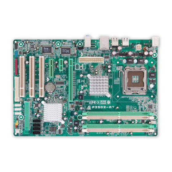
Page 7: Motherboard Layout
P35D2-A 7 OT HERBOARD AYOUT JCFAN1 JKBMS1 LGA775 JATX PW R1 CPU1 JUSB2 JUSB1 JATXPWR2 JRJ45USB1 Intel JAUDIO1 (for Ver 5.x) JAUDIO 2 (for Ver 6.x) JNFAN1(O ption al) JSPDIF_ OUT1(Op ti o na l) JCDIN1 PEX16_1 PEX1_1 JCMOS1 Intel BI OS ICH9 PEX4_1... -
Page 8: Chapter 2: Hardware Installation
Motherboard Manual CHAPTER 2: HARDWARE INSTALLATION (CPU) NST ALLING ENT RAL ROCESSING Special Notice: Remove Pin Cap before installation, and make good preservation for future use. When the CPU is removed, cover the Pin Cap on the empty socket to ensure pin legs won’t be damaged. Pin Cap Step 1: Pull the socket locking lever out from the socket and then raise the lever up to a 90-degree angle. - Page 9 P35D2-A 7 Step 2: Look for the triangular cut edge on socket, and the golden dot on CPU should point forwards this triangular cut edge. The CPU will fit only in the correct orientation. Step 2-1: Step 2-2: Step 3: Hold the CPU down firmly, and then lower the lever to locked position to complete the installation.
-
Page 10: Fan Headers
Motherboard Manual FAN H EADERS These fan headers support cooling-fans built in the computer. The fan cable and connector may be different according to the fan manufacturer. Connect the fan cable to the connector while matching the black wire to pin#1. -
Page 11: Installing System Memory
P35D2-A 7 NST ALLING YST EM EMORY A. Memory Modules Unlock a DIMM slot by pressing the retaining clips outward. Align a DIMM on the slot such that the notch on the DIMM matches the break on the Slot. Insert the DIMM vertically and firmly into the slot until the retaining chip snap back in place and the DIMM is properly seated. - Page 12 Motherboard Manual C. Dual Channel Memory installation To trigger the Dual Channel f unction of the motherboard, the memory module must meet the following requirements: Install memory module of the same density in pairs, shown in the f ollowing table. Dual Channel Status DDR2_A1 DDR2_A2 DDR2_B1 DDR2_B2 Enabled Enabled...
-
Page 13: Connectors And Slots
P35D2-A 7 ONNECT ORS AND LOT S FDD1: Floppy Disk Conne ctor The motherboard prov ides a standard floppy disk connector that supports 360K, 720K, 1.2M, 1.44M and 2.88M floppy disk ty pes. This connector supports the prov ided f loppy drive ribbon cables. IDE1: Hard Disk Conne ctor The motherboard has a 32-bit Enhanced PCI IDE Controller that prov ides PIO Mode 0~4, Bus Master, and Ultra DMA 33/66/100/133 f unctionality. - Page 14 Motherboard Manual PEX16_1: PCI-Express x16 Slot PCI-Express 1.0a compliant. Maximum theoretical realized bandwidth of 4GB/s simultaneously per direction, f or an aggregate of 8GB/s totally. PEX4_1: PCI-Expre ss x4 Slot PCI-Express 1.0a compliant. Maximum theoretical realized bandwidth of 1GB/s simultaneously per direction, f or an aggregate of 2GB/s totally.
-
Page 15: Chapter 3: Headers & Jumpers Setup
P35D2-A 7 CHAPTER 3: HEADERS & JUMPERS SETUP OW T O ET UP UMPERS The illustration shows how to set up jumpers. When the jumper cap is placed on pins, the jumper is “close”, if not, that means the jumper is “open”. - Page 16 Motherboard Manual JATXPWR2: ATX Powe r Source Conne ctor JATXPW2 allows user to connect 24-pin power connector on the ATX power supply. Assignment Assignment +3.3V +3.3V -12V +3.3V Ground Ground PS_ON Ground Ground Ground Ground Ground PW_OK Standby Voltage+5V +12V +12V Ground +3.3V...
-
Page 17: Cd-Rom Audio-In Connector
P35D2-A 7 JUSB3/JUSB4/JUSB5: He ade rs for USB 2.0 Ports at Front Panel This header allows user to connect additional USB cable on the PC f ront panel, and also can be connected with internal USB devices, like USB card reader. Assignment +5V (fused) +5V (fused) -
Page 18: Clear Cmos Header
Motherboard Manual JCMO S1: Cle ar CMOS Heade r By placing the jumper on pin2-3, it allows user to restore the BIOS saf e setting and the CMOS data, please carefully f ollow the procedures to avoid damaging the motherboard. Pin 1-2 Close: Normal Operation (default). - Page 19 P35D2-A 7 JSPDIF_O UT1: Digital Audio-out Conne ctor (O ptional) This connector allows user to connect the PCI bracket SPDIF output header. Assignment SPDIF_OUT Ground JCO M1: Se rial Port Connector The motherboard has a Serial Port Connector for connecting RS-232 Port. Assignment Carrier detect Received data...
- Page 20 Motherboard Manual JPRNT1: Printe r Port Connector This header allows you to connector printer on the PC. Assignment Assignment -Strobe Ground -ALF Data 6 Data 0 Ground -Error Data 7 Data 1 Ground -Init -ACK Data 2 Ground -Scltin Bus y Data 3 Ground Ground...
-
Page 21: Chapter 4: Useful Help
P35D2-A 7 CHAPTER 4: USEFUL HELP RIVER NST ALLAT ION OT E After you installed your operating system, please insert the Fully Setup Driver CD into your optical drive and install the driver for better system performance. You will see the following window after you insert the CD The setup guide will auto detect your motherboard and operating system. -
Page 22: Award Bios Beep Code
Motherboard Manual BIOS B WARD Beep Sound Meaning One long beep followed by two short Video card not found or v ideo card beeps memory bad High-low siren sound CPU overheated System will shut down automatically One Short beep when system boot-up No error found during POST Long beeps every other second No DRAM detected or install XT RA... -
Page 23: Troubleshooting
P35D2-A 7 4.4 T ROUBLESHOOT ING Probable Solution No power to the system at all Make sure power cable is Power light don’t illuminate, f an securely plugged in. inside power supply does not turn Replace cable. Contact technical support. Indicator light on key board does not turn on. -
Page 24: Chapter 5: Warpspeeder™ Iii
Motherboard Manual WARPSPEEDER™ III CHAPTER 5: NT RODUCT ION [WarpSpeeder™ III], a new powerful control utility, features three user-friendly functions including Overclock Manager, Overvoltage Manager, and Hardware Monitor. With the Overclock Manager, users can easily adjust the frequency they prefer or they can get the best CPU performance with just one click. The Overvoltage Manager, on the other hand, helps to power up CPU core voltage and Memory voltage. -
Page 25: Installation
P35D2-A 7 NST ALLAT ION 1. Execute the setup execution file, and then the following dialog will pop up. Please click “Next” button and follow the default procedure to install. 2. When you see the following dialog in setup procedure, it means setup is completed. -
Page 26: Warpspeeder™ Iii
Motherboard Manual ™ III PEEDER 1. Desktop Icon After the [WarpSpeeder™ III] has been installed, a [WarpSpeeder™ III] icon will appear on the desktop, just like the icon shown below. Now you can launch the [WarpSpeeder™ III] utility simply by double-clicking the desktop icon. - Page 27 P35D2-A 7 3. Overclock/Overvoltage Panel Click the Overclock/Overvoltage button in the Main Panel, the button will be highlighted and the Overclock/Overvoltage Panel will show up as the following figure. As you can see, the Overclock Panel is on the right side, and the Overvoltage Panel is on the left side.
- Page 28 Motherboard Manual O ve rclock Panel contains these fe atures: a. “Auto-Overclock”: User can click this button and [WarpSpeeder™ III] will set the best and stable performance and frequency automatically. A warning dialog as below will show up to notify you that the system may become unstable, click on “OK”...
- Page 29 P35D2-A 7 O ve rvoltage Panel contains these fe ature s: a. “CPU Voltage”: This function allows user to adjust CPU voltage. Click on “+” to increase or “-“ to decrease the CPU voltage. b. “Memory Voltage”: This function allows user to adjust Memory voltage. Click on “+” to increase or “-“...
- Page 30 Motherboard Manual 5. About Panel Click the “about” button in Main Panel, the button will be highlighted and the About Panel will show up as the following figure. In this panel, you can get model name and detail information in hints of all the chipset that are related to overclocking.
- Page 31 P35D2-A 7 This page is intentionally left blank.
-
Page 32: Appendencies: Spec In Other Language
Motherboard Manual APPENDENCIES: SPEC IN OTHER LANGUAGE ERMAN Ver 5.x Ver 6.x LGA 775 LGA 775 Intel Core2Duo / Core2 Quad / Celeron 4xx / Intel Core2Duo / Core2 Quad / Celeron 4xx / Pentium 4 / Pentium D / Celeron D Prozessoren Pentium 4 / Pentium D / Celeron D Prozessoren Unterstü... - Page 33 205 mm (B) X 305 mm (L) Windows 2000 / XP / VISTA Windows 2000 / XP / VISTA Biostar beh ält sich das Rech t vor, ohne Biostar beh ält sich das Rech t vor, ohne OS-Un terstüt Ankündigung die Un terstützung für ein Ankündigung die Un terstützung für ein...
-
Page 34: France
Motherboard Manual RANCE Ver 5.x Ver 6.x LGA 775 LGA 775 Processeu rs In tel Core2Duo / Core2 Quad / Processeu rs In tel Core2Duo / Core2 Quad / Celeron 4xx / Pentium 4 / Pen tium D / Celeron D Celeron 4xx / Pentium 4 / Pen tium D / Celeron D Prend en charge les techn ologies Prend en charge les techn ologies... - Page 35 Windows 2000 / XP / VISTA Windows 2000 / XP /VISTA Support SE Biostar se réserve le droit d'ajouter ou de Biostar se réserve le droit d'ajouter ou de supprimer le support de SE avec ou san s préavis. supprimer le support de SE avec ou san s préavis.
-
Page 36: Italian
Motherboard Manual T ALIAN Ver 5.x Ver 6.x LGA 775 LGA 775 Processore Intel Core 2Duo / Core 2Quad / Processore Intel Core 2Duo / Core 2Quad / Celeron 4xx / Pe ntium 4 / Pentium D / Celeron 4xx / Pe ntium 4 / Pentium D / Celeron D Celeron D Supporto di Hyper -Threadi ng / Execute... - Page 37 Windows 2000 / XP / VISTA Windows 2000 / XP / VISTA Sistemi Biostar si riserva il diritto di aggiungere o Biostar si riserva il diritto di aggiungere o operativi rimuovere il supporto di qualsiasi sistema rimuovere il supporto di qualsiasi sistema supportati operativo se nza pre avviso.
-
Page 38: Spanish
Motherboard Manual PANISH Ver 5.x Ver 6.x LGA 775 LGA 775 Procesador Intel Core2Duo / Core2 Quad / Procesador Intel Core2Duo / Core2 Quad / Celeron 4xx / Pentium 4 / Pen tium D / Celeron D Celeron 4xx / Pentium 4 / Pen tium D / Celeron D Admite Hyper-Threading / Bit de deshabilitación Admite Hyper-Threading / Bit de deshabilitación de ejecu ción / Intel SpeedStep®... - Page 39 Windows 2000 / XP / VISTA Windows 2000 / XP / VISTA sistema Biostar se reserva el derecho de añ adir o retirar Biostar se reserva el derecho de añ adir o retirar operativo el soporte de cualqu ier SO con o sin aviso previo.
-
Page 40: Portuguese
Motherboard Manual ORT UGUESE Ver 5.x Ver 6.x LGA 775 LGA 775 Processador In tel Core2Duo / Core2 Quad / Processador In tel Core2Duo / Core2 Quad / Celeron 4xx / Pentium 4 / Pen tium D / Celeron D Celeron 4xx / Pentium 4 / Pen tium D / Celeron D Suporta as tecn ologias Hyper-Threading / Suporta as tecn ologias Hyper-Threading /... - Page 41 Windows 2000 / XP / VISTA Windows 2000 / XP / VISTA Sistemas A Biostar reserva-se o direito de adicionar ou A Biostar reserva-se o direito de adicionar ou operativos remover suporte para qu alquer sistema remover suporte para qu alquer sistema suportados operativo com ou sem aviso prévio.
-
Page 42: Polish
Motherboard Manual OLISH Ver 5.x Ver 6.x LGA 775 LGA 775 Procesor In tel Core2Duo / Core2 Quad / Procesor In tel Core2Duo / Core2 Quad / Celeron 4xx / Pentium 4 / Pen tium D / Celeron D Celeron 4xx / Pentium 4 / Pen tium D / Celeron D Procesor Obsługa Hyper-Th reading / Execu te Disable Bit / Obsługa Hyper-Th reading / Execu te Disable Bit /... - Page 43 Obsluga Windows 2000 / XP / VISTA Windows 2000 / XP / VISTA systemu Biostar zastrzega sobie prawo dodawania lub Biostar zastrzega sobie prawo dodawania lub operacyjne odwoływania obsługi dowoln ego systemu odwoływania obsługi dowoln ego systemu operacyjnego bez powiadomien ia.
-
Page 44: Russian
Motherboard Manual USSIAN Ver 5.x Ver 6.x LGA 775 LGA 775 Процессор In tel Core2Duo / Core2 Quad / Процессор In tel Core2Duo / Core2 Quad / Celeron 4xx / Pentium 4 / Pen tium D / Celeron D Celeron 4xx / Pentium 4 / Pen tium D / Celeron D (центральн... - Page 45 Windows 2000 / XP / VISTA Windows 2000 / XP / VISTA Поддержка Biostar сохран яет за собой право добавлять Biostar сохран яет за собой право добавлять или удалять средства обеспечения для OS с или удалять средства обеспечения для OS с...
-
Page 46: Arabic
Motherboard Manual RABIC Ver 6.x Ver 5.x LGA 775 LGA 775 ﻣﻌ ﺎ ﻟﺠﺎتIntel Core2Du o / Core2 Quad / Celeron 4 xx ﻣﻌ ﺎ ﻟﺠﺎتIntel Core2Du o / Core2 Quad / Celeron 4 xx / Pentium 4 / Pen tiu m D / Celeron D / Pentium 4 / Pen tiu m D / Celeron D ﺼﻞ... - Page 47 ﻣﻘﺒﺲ ﺹﻮت ارﺕﻔﺎع ﻣﻢ ﻋﺮض ﻣﻢ ارﺕﻔﺎع ﻣﻢ ﻋﺮض ﻣﻢ ا ﻝ ﻠﻮﺣﺔ ﺣﺠﻢ Windows 2000 / XP / VISTA Windows 2000 / XP / VISTA ﺕﺤﺘﻔﻆBiostar ﺕﺤﺘﻔﻆBiostar ﺏﺈﺧﻄﺎر ﺕﺸﻐﻴﻞ ﻥﻈﺎم ﻷي اﻝﺪﻋﻢ إزاﻝﺔ أو إﺿﺎﻓﺔ ﻓﻲ ﺏﺤﻘﻬﺎ ﺏﺈﺧﻄﺎر...
-
Page 48: Japanese
Motherboard Manual APANESE Ver 5.x Ver 6.x LGA 775 LGA 775 Intel Core2Duo / Core2Qu ad / Celeron 4xx / Intel Core2Duo / Core2Qu ad / Celeron 4xx / Pentium 4 / Pentium D / Celeron D processor Pentium 4 / Pentium D / Celeron D processor Hyper-Threading / E xecute Disable Bit / Hyper-Threading / E xecute Disable Bit / Enhanced In tel SpeedStep®... - Page 49 背面パネル LANポート LANポート USBポート USBポート オーディオジャック オーディオジャック ボードサイズ 205 mm (幅) X 305 mm (高さ) 205 mm (幅) X 305 mm (高さ) Windows 2000 / XP / VISTA Windows 2000 / XP / VISTA OSサポート Biostarは事前のサポートなしにOSサポートを追加ま Biostarは事前のサポートなしにOSサポートを追加ま たは削除する権利を留保します。 たは削除する権利を留保します。 2007/07/05...
- Page 50 P35D2-A7 BIOS Setup BIOS Setup ....................1 1 Main Menu ..................... 3 2 Standard CMOS Features..............7 3 Advanced BIOS Features ..............9 4 Advanced Chipset Features..............16 5 Integrated Peripherals................. 18 6 Power Management Setup..............23 7 PnP/PCI Configurations..............29 8 PC Health Status ..................
-
Page 51: Bios Setup
P35D2-A7 BIOS Setup Introduction The purpose of this manual is to describe the settings in the Phoenix-Award™ BIOS Setup program on this motherboard. The Setup program allows users to modify the basic system configuration and save these settings to CMOS RAM. -
Page 52: Acpi Support
P35D2-A7 ACPI Support Phoenix-Award ACPI BIOS support Version 1.0b of Advanced Configuration and Power interface specification (ACPI). It provides ASL code for power management and device configuration capabilities as defined in the ACPI specification, developed by Microsoft, Intel and Toshiba. -
Page 53: Main Menu
P35D2-A7 1 Main Menu Once you enter Phoenix-Award BIOS™ CMOS Setup Utility, the Main Menu will appear on the screen. The Main Menu allows you to select from several setup functions. Use the arrow keys to select among the items and press <Enter>... -
Page 54: Load Optimized Defaults
P35D2-A7 Advanced BIOS Features This submenu allows you to configure advanced features of the BIOS. Advanced Chipset Features This submenu allows you to configure special chipset features. Integrated Peripherals This submenu allows you to configure certain IDE hard drive options and Programmed Input/ Output features. -
Page 55: Set Supervisor Password
P35D2-A7 Set Supervisor Password Setting the supervisor password will prohibit everyone except the supervisor from making changes using the CMOS Setup Utility. You will be prompted with to enter a password. Set User Password If the Supervisor Password is not set, then the User Password will function in the same way as the Supervisor Password. - Page 56 P35D2-A7 Upgrade BIOS This submenu allows you to upgrade bios.
-
Page 57: Standard Cmos Features
P35D2-A7 2 Standard CMOS Features The items in Standard CMOS Setup Menu are divided into several categories. Each category includes no, one or more than one setup items. Use the arrow keys to highlight the item and then use the<PgUp> or <PgDn> keys to select the value you want in each item. - Page 58 P35D2-A7 Item Options Description Press <Enter> to enter the IDE Channel 1 Options are in its sub sub menu of detailed menu. Master / Slave options. 360K, 5.25 in 1.2M, 5.25 in Select the type of floppy Drive A 720K, 3.5 in disk drive installed in your 1.44M, 3.5 in...
-
Page 59: Advanced Bios Features
P35D2-A7 3 Advanced BIOS Features Figure 3: Advanced BIOS Setup CPU Feature... - Page 60 P35D2-A7 Delay Prior to Thermal Set this item to enable the CPU Thermal function to engage after the specified time. The Choices: 4 Min, 8 Min, 16Min (default), 32 Min. Thermal Management This option allows you to select the way to control the “Thermal Management.”...
- Page 61 P35D2-A7 Cache Setup CPU L3 Cache Depending on the CPU/chipset in use, you may be able to increase memory access time with this option. Enabled (default) Enable cache. Disabled Disable cache. Boot Seq & Floppy Setup This item allows you to setup boot sequence & Floppy.
-
Page 62: Hard Disk Boot Priority
P35D2-A7 Hard Disk Boot Priority The BIOS will attempt to arrange the Hard Disk boot sequence automatically. You can change the Hard Disk booting sequence here. The Choices: Pri. Master, Pri. Slave, Sec. Master, Sec. Slave, USB HDD0, USB HDD1, USB HDD2, and Bootable Add-in Cards. -
Page 63: Virus Warning
P35D2-A7 Virus Warning This option allows you to choose the VIRUS Warning feature that is used to protect the IDE Hard Disk boot sector. If this function is enabled and an attempt is made to write to the boot sector, BIOS will display a warning message on the screen and sound an alarm beep. -
Page 64: Security Option
P35D2-A7 Typematic Rate (Chars/Sec) Sets the rate at which a keystroke is repeated when you hold the key down. The Choices: 6 (default), 8, 10, 12, 15, 20, 24, 30. Typematic Delay (Msec) Sets the delay time after the key is held down before it begins to repeat the keystroke. -
Page 65: Summary Screen Show
P35D2-A7 Small Logo(EPA) Show This item allows you to select whether the “Small Logo” shows. The Choices: Disabled (default), Enabled. Summary Screen Show This item allows you to enable/disable the summary screen. Summary screen means system configuration and PCI device listing. -
Page 66: Advanced Chipset Features
P35D2-A7 4 Advanced Chipset Features This submenu allows you to configure the specific features of the chipset installed on your system. This chipset manage bus speeds and access to system memory resources, such as DRAM. It also coordinates communications with the PCI bus. - Page 67 P35D2-A7 Memory Hole At 15M-16M You can reserve this area of system memory for ISA adapter ROM. When this area is reserved it cannot be cached. Check the user information of peripherals that need to use this area of system memory for the memory requirements.
-
Page 68: Integrated Peripherals
P35D2-A7 5 Integrated Peripherals Figure 5. Integrated Peripherals OnChip IDE Device Highlight the “Press Enter” label next to the “OnChip IDE Device” label and press enter key will take you a submenu with the following options:... - Page 69 P35D2-A7 IDE HDD Block Mode Block mode is also called block transfer, multiple commands, or multiple sectors read / write. If your IDE hard drive supports block mode (most new drives do), select Enabled for automatic detection of the optimal number of block mode (most new drives do), select Enabled for automatic detection of the optimal number of block read / write per sector where the drive can support.
-
Page 70: Super Io Device
P35D2-A7 Super IO Device Press Enter to configure the Super I/O Device. Onboard FDC Controller Select enabled if your system has a floppy disk controller (FDC) installed on the system board and you wish to use it. If you installed another FDC or the system uses no floppy drive, select disabled in this field. -
Page 71: Usb Device Setting
P35D2-A7 Parallel Port Mode This item allows you to determine how the parallel port should function. The default value is SPP. The Choices: SPP (default) Using Parallel port as Standard Printer Port. Using Parallel Port as Enhanced Parallel Port. Using Parallel port as Extended Capabilities Port. -
Page 72: Onboard Lan
P35D2-A7 USB Operation Mode Auto decide USB device operation mode. [High Speed]: If USB device was high speed device,then it operated on high speed mode. If USB device was full/low speed,then it operated on full/low speed mode. [Full/Low Speed]: All of USB device operated on full/low speed mode. -
Page 73: Power Management Setup
P35D2-A7 6 Power Management Setup The Power Management Setup Menu allows you to configure your system to utilize energy conservation and power up/power down features. Figure 6. Power Management Setup ACPI & Wake Up Events... - Page 74 P35D2-A7 ACPI Function This item displays the status of the Advanced Configuration and Power Management (ACPI). The Choices: Enabled (default), Disabled. ACPI Suspend Type The item allows you to select the suspend type under the ACPI operating system. The Choices:...
- Page 75 P35D2-A7 operating system, before this function will work. POWER ON Function This item allows you to choose the power on method. The Choices: Button Only (default), Password, Hot Key, Mouse Move/Click, Mouse Double Click, Any Key, Keyboard 98. KB Power ON Password Input password and press Enter to set the Keyboard power on password.
-
Page 76: Power Management
P35D2-A7 FDD, COM, LPT Port You can enable or disable FDD, COM, and LPT port under this item. The Choices: Disabled (default), Enabled. PCI PIRQ [A-D]# You can enable or disable PCI PIRQ [A-D]# under this item. The Choices: Disabled (default), Enabled. -
Page 77: Video Off In Suspend
P35D2-A7 Video Off In Suspend This item determines the monitor status when the system is in Suspend mode. The Choices: Yes (default), No. Suspend Type Select the Suspend Type. The Choices: Stop Grant (default), PwrOn Suspend. Modem Use IRQ This determines the IRQ, which can be applied in MODEM use. - Page 78 P35D2-A7 HPET Mode This item allows you to select the way the High Precision Event Timer works. The Choices: 32-bit mode (default), 64-bit mode.
-
Page 79: Pnp/Pci Configurations
P35D2-A7 7 PnP/PCI Configurations This section describes configuring the PCI bus system. PCI, or Personal Computer Interconnect, is a system which allows I/O devices to operate at speeds nearing the speed of the CPU itself uses when communicating with its own special components. -
Page 80: Irq Resources
P35D2-A7 IRQ Resources This submenu will allow you to assign each system interrupt a type, depending on the type of device using the interrupt. When you press the “Press Enter” tag, you will be directed to a submenu that will allow you to configure the system interrupts. -
Page 81: Pc Health Status
P35D2-A7 8 PC Health Status Figure 8: PC Health Status Smart Fan Option... -
Page 82: Shutdown Temperature
P35D2-A7 CPU Smart Fan This item allows you to control the CPU/System Fan. The Choices: Auto (default), Disabled, 4-pin, 3-pin.. Smart Fan Calibration Choose this item and then the BIOS will auto test and detect the CPU/System fan functions and show CPU/System fan speed. - Page 83 P35D2-A7 Current CPU Temp This field displays the current temperature of CPU. Current CPU FAN Speed This field displays the current speed of CPU fan. Current SYS FAN Speed This field displays the current speed of SYSTEM fan.
-
Page 84: Performance Booster Zone
P35D2-A7 9 Performance Booster Zone Figure 9: Performance Booster Zone CPU Clock Ratio This item allows you to select the CPU Ratio. Min= 6 Max= 50, Key in a DEC number. The Choices: 6X (default). CPU Clock This item allows you to select CPU Clock, and CPU over clocking. -
Page 85: System Memory Frequency
P35D2-A7 This action will boot-up the system according to FSB of the processor It’s strongly recommended to set CPU Vcore and clock in default setting. If the CPU Vcore and clock are not in default setting, it may cause CPU or M/B damage. -
Page 86: Cpu Voltage
P35D2-A7 CAS Latency Time When synchronous DRAM is installed, the number of clock cycles of CAS latency depends on the DRAM timing. The Choices: Auto (default), 5, 6. DRAM RAS# to CAS# Delay This field allows you to insert a timing delay between the CAS and RAS strobe signals, used when DRAM is written to, read from, or refreshed. -
Page 87: Memory Voltage
P35D2-A7 (G)MCH Voltage This item allows you to select (G)MCH Voltage Control. The Choices: 1.25V (default), 1.35V, 1.45V, 1.55V. Memory Voltage This item allows you to select memory Voltage Control. The Choices: 1.90V (default), 2.00V, 2.10V, 2.20V, 2.30V, 2.40V, 2.50V,...
Need help?
Do you have a question about the P35D2-A7 and is the answer not in the manual?
Questions and answers