Table of Contents
Advertisement
Quick Links
This .pdf document is bookmarked
Operating Instructions and Parts Manual
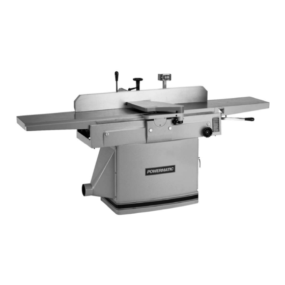
12-inch Jointer
Model 1285
For machines with serial no. 11121285640 and higher
WALTER MEIER (Manufacturing) Inc.
427 New Sanford Road
LaVergne, Tennessee 37086
Part No. M-0460216
Ph.: 800-274-6848
Revision C4 02/2012
www.waltermeier.com
Copyright © 2012 Walter Meier (Manufacturing) Inc.
Advertisement
Table of Contents

Related Manuals for Powermatic 1285T


Summary of Contents for Powermatic 1285T
- Page 1 This .pdf document is bookmarked Operating Instructions and Parts Manual 12-inch Jointer Model 1285 For machines with serial no. 11121285640 and higher WALTER MEIER (Manufacturing) Inc. 427 New Sanford Road LaVergne, Tennessee 37086 Part No. M-0460216 Ph.: 800-274-6848 Revision C4 02/2012 www.waltermeier.com Copyright ©...
-
Page 2: Warranty And Service
This warranty covers only the initial purchaser of the product. WHAT IS THE PERIOD OF COVERAGE? The general POWERMATIC warranty lasts for the ti m e period specified in the product literature of each product. WHAT IS NOT COVERED? The Five Year Warranty does not cover products used for commercial, industrial or educational purposes. Products with a Five Year Warranty that are used for commercial, industrial or education purposes revert to a One Year Warranty. -
Page 3: Table Of Contents
Table of Contents Warranty and Service..........................2 Warning .............................4 Introduction ............................7 Specifications .............................7 Unpacking ............................8 Contents of the Shipping Container ....................8 Assembly ............................9 Fence Installation ..........................9 Switch Arm ........................... 10 Dust Hood............................. 10 Grounding Instructions ........................10 Voltage Conversion ........................11 Extension cords.......................... -
Page 4: Warning
Warning 1. Read and understand the entire owner’s manual before attempting assembly or operation. 2. Read and understand the warnings posted on the machine and in this manual. Failure to comply with all of these warnings may cause serious injury. 3. - Page 5 19. Keep visitors a safe distance from the work area. Keep children away. 20. Make your workshop child proof with padlocks, master switches or by removing starter keys. 21. Give your work undivided attention. Looking around, carrying on a conversation and “horse-play” are careless acts that can result in serious injury.
- Page 6 36. Before attempting to joint or plane, each work piece must be carefully examined for stock condition and grain orientation. NOTE: At certain times it may be necessary to plane against the grain when working with a swirl grain wood or burls. With this type of work the operator must use a lesser depth of cut and a slow rate of feed.
-
Page 7: Introduction
Introduction This manual is provided by Walter Meier (Manufacturing) Inc., covering the safe operation and maintenance procedures for a Model 1285 Jointer. This manual contains instructions on installation, safety precautions, general operating procedures, maintenance instructions and parts breakdown. This machine has been designed and constructed to provide years of trouble free operation if used in accordance with instructions set forth in this manual. -
Page 8: Unpacking
Contents of the Shipping Container Unpacking Jointer Open shipping container and check for shipping Fence Assembly damage. Report any damage immediately to Dust Hood your distributor and shipping agent. Compare the contents of your container with the following Knife Setting Gauge (for straight knife parts list to make sure all parts are intact. -
Page 9: Assembly
Assembly Tools need for assembly: 10mm hex wrench (provided) 10-12mm combination wrench (provided) forklift or hoist with straps cross-point screwdriver 1. Remove top and sides of crate from around the machine. 2. Remove the dust hood and the fence Figure 1 assembly from the skid. -
Page 10: Switch Arm
Switch Arm The arm (Figure 3) on which the push button switch is located is shipped in the down position. The arm should be pivoted to upright position as shown. Tighten the two screws with a 10mm wrench. Figure 3 Dust Hood Before attaching the dust hood, make sure the hole in the dust chute is concealed by the dust... -
Page 11: Voltage Conversion
PJ1285-109). The 460 volt contactor is available through your authorized Powermatic distributor, or by calling 1-800- 274-6848. 5. If you are using a plug on the jointer’s power Figure 7 cord, install an appropriate 460 volt plug. 6. After wiring for the new voltage, turn on the machine and observe the rotation of the cutterhead;... -
Page 12: Adjustments
Adjustments Disconnect jointer from power supply before making adjustments. Drive Belt Tension To check the tension of the drive belts: 1. Remove the three cap nuts and flat washers on the pulley cover with a 9/16 wrench, and remove the guard to expose the belts and pulleys. - Page 13 2. Place a straight edge on the outfeed table and extending over the cutterhead, as shown in Figure 13. 3. Rock the cutterhead slightly so that a knife tip contacts the straight edge. If the knife tip just contacts the straight edge without moving the straight edge, then the outfeed table is at the proper height.
-
Page 14: Setting Infeed Table Height (Depth Of Cut)
Setting Infeed Table Height (Depth of Cut) 1. To set the cutting depth, loosen handwheel (A, Figure 17) by turning counterclockwise. 2. Move table adjustment arm (B, Figure 17) up or down to raise or lower infeed table. The pointer (C, Figure 17) shows the depth of cut on the adjoining scale. - Page 15 5. It is recommended when replacing knives that you clean the knife slots in the cutterhead. Remove the gib along with the gib screws, and remove the two springs. Clean the cutterhead slot of any debris or dust that might prevent the knife from seating properly.
-
Page 16: Replacing Knife Inserts (Helical Cutterhead)
Replacing Knife Inserts (Helical Cutterhead) Jointer knife inserts are very sharp. Use care and proceed slowly when working with or around the cutterhead. The helical cutterhead is a solid steel design that holds 42 two-sided knife inserts, and two rabbet knife inserts on the outboard end of the cutterhead. -
Page 17: Fence Adjustments
Fence Adjustments The fence (A, Figure 22) tilts backward and forward to 45 degrees. It has a 90-degree stop (B, Figure 22) and a 45-degree stop (C, Figure 22). To tilt fence forward: 1. Loosen the lock handle (D, Figure 22) and tilt the fence forward using the handle (E, Figure 22). -
Page 18: Cutter Guard Tension
To check and adjust the 45-degree stop: 1. Loosen lock handle (D, Figure 22) and tilt fence until it contacts the 45-degree stop (C, Figure 22). 2. Place a machinist’s protractor or similar device set at 45 degrees on the table and against the fence. -
Page 19: Hand Placement
Hand Placement At the start of the cut, the left hand holds the workpiece firmly against the infeed table and fence, while the right hand pushes workpiece toward the knives. After the cut is under way, the jointed surface of the workpiece rests firmly on the outfeed table. -
Page 20: Jointing Warped Surfaces
Use push blocks to rabbet cut whenever possible. The rabbeting capacity is 3/4”. 1. Disconnect machine from power source. 2. Set fence for desired width of rabbet. 3. Check width of the rabbet by measuring the distance from the end of a knife in the cutterhead to the fence. -
Page 21: Maintenance
Maintenance Disconnect machine from power source before performing maintenance. Failure to comply may cause serious injury. Check all screws and fasteners occasionally and keep them tightened securely. Inspect cords; a cord that is frayed or damaged in any way should be replaced immediately. The table and fence surfaces must be kept clean and free of rust for best results. -
Page 22: Knife Inserts (Helical Cutterhead)
If the jointer is used often, keeping a spare set of knife inserts on hand is recommended. Knife inserts (stock no. 6400013) may be ordered from your authorized Powermatic distributor or by calling 1-800-274-6848. Gum and pitch which collect on the knife inserts... -
Page 23: Whetting Knives (Straight Cutterhead)
Knives (stock no. 6292535) may be ordered from your authorized Powermatic distributor or by calling 1-800-274-6848. Gum and Pitch which collect on the knives cause excessive friction as the work continues,... - Page 24 Troubleshooting – Operating Problems Trouble Probable Cause Remedy Finished stock is Raise outfeed table until it aligns with concave on back Knife is higher than outfeed table. tip of knife. (see page 13) end. Finished stock is Lower outfeed table until it aligns with Outfeed table is higher than knife.
- Page 25 Troubleshooting – Mechanical and Electrical Problems Trouble Probable Cause Remedy Machine will not Verify unit is connected to power, and No incoming power. start/restart or on-switch is pushed in completely. repeatedly trips When jointer overloads on the circuit circuit breaker or breaker built into the motor starter, it blows fuses.
- Page 26 Trouble Probable Cause Remedy Double check to confirm all electrical connections are correct and properly tight. The electrical connections other than the motor are pre-assembled and tested at the factory. Therefore, Miswiring of the unit. the motor connections should be double checked as the highest probability for error.
-
Page 27: Optional Accessories
Replacement parts are listed on the following pages. To order parts or reach our service department, call 1-800-274-6848 Monday through Friday (see our website for business hours: www.powermatic.com). Having the Model Number and Serial Number of your machine available when you call will allow us to... -
Page 28: Parts List: Stand Assembly
28 .... TS-1533052 ....Machine Screw, Pan Head, Phillips ....M5x16......2 29 .... PJ1285-129 .....Switch Cord..................1 30 .... PJ1285-130 .....Motor Cord ..........1Ph........1 ....PJ1285-130A...Motor Cord ..........3Ph........1 31 .... PJ1285-131 .....Power Cord ..........1Ph........1 ....PJ1285-131A...Power Cord ..........3Ph........1 32 .... 3312341 ....Powermatic Logo ................1... -
Page 29: Stand Assembly
Stand Assembly... -
Page 30: Parts List: Table Assembly
Parts List: Table Assembly Index No. Part No. Description Size 1 ....6292525 ....Base ....................1 2 ....6292526 ....Bar, Table Raising Link ............... 2 3 ....6292527 ....Bracket ....................2 4 ....TS-0680041 ....Lock Washer ..........3/8” ........8 5 ....TS-0209051 ....Socket Head Cap Screw ......3/8”-16x1” ......4 6 .... - Page 31 Table Assembly...
-
Page 32: Parts List: Motor Pulley Assembly
Parts List: Motor Pulley Assembly Index No. Part No. Description Size 1 ....6292512 ....Motor ............3HP 3Ph ......1 ....6292512-MF ....Motor Fan (not shown) ............... 1 ....6292512-MFC ..Motor Fan Cover (not shown) ............. 1 ....6292563 ....Motor ............3HP 1Ph ......1 .... -
Page 33: Motor Pulley Assembly
Motor Pulley Assembly... -
Page 34: Parts List: Cutterhead Guard Assembly
Parts List: Cutterhead Guard Assembly Index No. Part No. Description Size 1 ....6292581 ....Ledge, Rabbet ..................1 2 ....6292582 ....Guard ....................1 3 ....6292583 ....Shaft ....................1 4 ....6292584 ....Spring ....................1 5 ....6292585 ....Collar, Shaft ..................1 6 .... -
Page 35: Cutterhead Guard Assembly
Cutterhead Guard Assembly... -
Page 36: Parts List: Straight Cutterhead Assembly
Parts List: Straight Cutterhead Assembly Index No. Part No. Description Size ....6292550 ....Cutterhead Assembly (Items 1 thru 19)……… ........1 ....6292561 ....Cutterhead ..................1 2 ....PJ1696-002 .....Left Bearing Housing ................1 3 ....BB-6204ZZ ....Bearing .............6204ZZ ......2 4 .... -
Page 37: Straight Cutterhead Assembly
Straight Cutterhead Assembly... -
Page 38: Parts List: Helical Cutterhead Assembly
Parts List: Helical Cutterhead Assembly Index No. Part No. Description Size ....PJ1285-600 .....Cutterhead Assembly (Items 1 thru 22)……… ........1 ....PJ1285-601 .....Cutterhead ..................1 2 ....PJ1696-002 .....Left Bearing Housing ................1 3 ....BB-6204ZZ ....Ball Bearing..........6204ZZ ......2 4 .... -
Page 39: Helical Cutterhead Assembly
Helical Cutterhead Assembly... -
Page 40: Parts List: Fence Assembly
Parts List: Fence Assembly Index No. Part No. Description Size 1 ....6292592 ....Support, Fence ................... 1 2 ....6292593 ....Bracket ....................1 3 ....6292594 ....Column, Gear ..................1 4 ....6292595 ....Guard ....................1 5 ....TS-1503031 ....Socket Head Cap Screw ......M6x12......2 6 .... -
Page 41: Fence Assembly
Fence Assembly... -
Page 42: Electrical Connections - 1 Phase
Electrical Connections – 1 Phase... -
Page 43: Electrical Connections - 3 Phase
Electrical Connections – 3 Phase... - Page 44 WALTER MEIER (Manufacturing) Inc. 427 New Sanford Road LaVergne, Tennessee 37086 Phone: 800-274-6848 www.powermatic.com www.waltermeier.com...
Need help?
Do you have a question about the 1285T and is the answer not in the manual?
Questions and answers