
Related Manuals for Powermatic 1200HD


Summary of Contents for Powermatic 1200HD
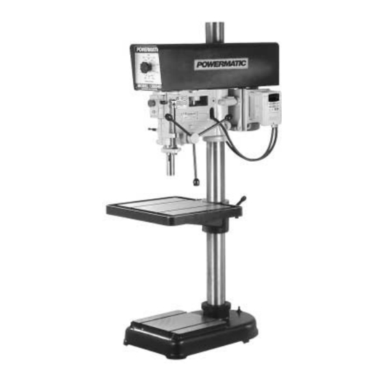
- Page 1 20" DRILL PRESS Model 1200HD Instruction Manual & Parts List M-0460237 (800) 248-0144 www.wmhtoolgroup.com...
-
Page 2: More Information
This manual has been prepared for the owner and operators of a Powermatic Model 1200HD Drill Press. Its purpose, aside from machine operation, is to promote safety through the use of accepted correct operating and maintenance procedures. Completely read the safety and main- tenance instructions before operating or servicing the machine. -
Page 3: Table Of Contents
Head Assembly ........................20-21 Electrical Schematics 1200HD ............................22 1200HD when used with Reversing Foot Switch ................ 23 Trouble-shooting Tips ......................... 24 Table 1A: Drilling Feeds - Speed - Horsepower Required ..............25 TABLE 1B: Drilling Feeds - Speed - Horsepower Required ............... 26 TABLE 2: Reaming Speeds - High Speed Steel Tools - Materials - RPM .......... -
Page 4: Instructions
Read, understand and follow the safety and operating instructions found in this manual. Know the limita- tions and hazards associated with a 1200HD Drill Press. A safety rules decal is installed on the belt guard of this machine to serve as a reminder of basic safety practice. - Page 5 Powermatic disclaims any real or implied warranty and holds itself harmless for any injury that may result from the use. Do not equip a 1200HD Drill Press with a motor larger than 2 horsepower nor with a motor with a speed greater than 1800 rpm unless specifically authorized to do so in writing by Powermatic.
-
Page 6: Decals
UNCLAMPING HEAD WITH COLUMN CLAMP SCREWS. SEE INSTRUCTIONS FOR PROPER SPINDLE HEAD RAISING AND LOWERING. 3408211 3408259 SPECIFICATIONS (Model 1200HD Drill Press) Spindle Travel ............................6" Quill Diameter ........................... 2-3/4" Column Diameter ..........................4-1/2" Column Wall Thickness ........................1/2" Column Length ............................. 66"... -
Page 7: Dimensional Drawings
DIMENSIONAL DRAWINGS (Model 1200HD Drill Press) FIGURE 1... -
Page 8: Installation, Maintenance & Adjustments
INSTALLATION, MAINTENANCE AND ADJUSTMENTS RECEIVING floor through holes provided in leveling screws (3/8" dia. lag screws). Remove drill press from shipping container and QUILL ADJUSTMENT check for damage. Report any damage to the carrier and to your distributor immediately. Attach accessories shipped with drill press, then clean Lateral play or bellmouthing can develop between the quill and head casting bands due to wear. -
Page 9: Replacing Spindles On Quill Assembly
"QUILL RETURN SPRING ADJUSTMENT." LUBRICATIONS All ball bearings in your Powermatic drill press are sealed for life, requiring no lubrication. Points requir- ing lubrication are: Internal spline drive assembly. Keep this area well lubricated with a good grade non-hardening grease, such as Fiske Company "Lubriplate."... -
Page 10: Drill Press Operations
SAE 10W or automatic transmission On all 1200HD models, a knob (I) is used to oil every 90 days. change speed. Apply Lubriplate to quill pinion every 90 days. -
Page 11: Inverter Drive System
NOTE: If there is a power outage while operating As the breakthrough point is reached, always slow the 1200HD Drill Press, turn the switch to the OFF feed rate down slightly to assist in elimination of position, disconnect power source, wait thirty... -
Page 12: Production & Tilting Table With Table Raising Rack
PARTS LIST: Production & Tilting Table with Table Raising Rack (1200HD) Part No. Description Quantity 2298013 Elevating Gear Box Housing Assembly (Items 1 thru 15) ........1 6624006 Groove Pin, 1/4 x 2-3/4 Lg..................3268201 Nylon Handle ......................1 6715132 Round Head Screw, 5/16-18 x 1/2 ................ -
Page 13: Production & Tilting Table With Table Raising Rack
Production & Tilting Table with TABLE RAISING RACK... -
Page 14: Electronic Variable Speed Assembly
PARTS LIST: Electronic Variable Speed Assembly (1200HD) Part No. Description Quantity 2387006 Step Cone Sheave Kit Assembly (Items 1 thru 52) ............1 2144004 Drive Spline Sheave Assembly (Items 1 thru 6) ............1 6060054 Ball Bearing, NTN ......................2 6807136 Sheave - HTD Spindle .................... - Page 15 PARTS LIST: Electronic Variable Speed Assembly (1200HD) Part No. Description Quantity 6715016 Cup Point Socket Set Screw, 5/16-18 x 5/16 ............... 1 3312343 Powermatic Logo Label (one not shown) ..............2 3408259 Warning Label (not shown) ..................1 3330368 Instruction Plate 1200HD ..................... 1 3719190 Step Cone Sheave .......................
-
Page 16: Electronic Variable Speed Assembly
Electronic Variable Speed Assembly (1200HD) -
Page 17: Spindle Table, Legs & Column Mounting Bracket Assembly
PARTS LIST: Spindle Table, Legs & Column Mounting Bracket Assy. (1200HD) Part No. Description Quantity 3098005 Bench Model Column for Spindle Table ..............1 6718009 Hex Head Cap Screw, for Spindle Table ..............4 6718025 Hex Head Cap Screw, 1/2-13 x 2-1/2 for Spindle Table ........... 2 3064078 Column Mounting Bracket for Spindle Table ............ - Page 18 PARTS LIST: Head Raising Assembly (1200HD) Part No. Description Quantity 2298016 Head Raising Mechanism (Items 1 thru 15) 1 Spindle Table ........1 3237002 Gear ........................1 3237001 Gear ........................1 6714004 Socket Set Screw, 1/4-20 x 1/4 ................2 3388015 Square Key, 3/16 x 3/16 x 2-1/4 ................
-
Page 19: Head Raising Assembly
Head Raising Assembly (1200HD) -
Page 20: Head Assembly
PARTS LIST: Head Assembly (1200HD) Part No. Description Quantity 2268006 Turret Handle Assembly (Items 1 and 2) ..............1 3406206 Phenolic Knob ......................3 3670025 Knob Handle ......................3 2277016 Head Assembly (Items 3 thru 39) ................1 2686003 Pinion Hub Assembly (Items 3 thru 6) ..............1 3301003 Turret Hub ....................... -
Page 21: Head Assembly
Head Assembly (1200HD) -
Page 22: 1200Hd
ELECTRICAL SCHEMATIC 1200HD... -
Page 23: 1200Hd When Used With Reversing Foot Switch
ELECTRICAL SCHEMATIC 1200HD (when used with Reversing Foot Switch) -
Page 24: Trouble-Shooting Tips
Trouble-Shooting for Model 1200HD Drill Press PROBLEM POSSIBLE CAUSE SOLUTION Excessive vibration. 1. Improper belt tension. 1. Adjust belt tension. 2. Uneven belt wear (hard spots). 2. Replace belt. 3. Motor or spindle pulley out-of-balance. 3. Balance or repair problem pulley 4. -
Page 25: Table 1A: Drilling Feeds - Speed - Horsepower Required
TABLE 1A: DRILLING FEEDS - SPEED - HORSEPOWER REQUIRED CAST IRON FEED PER DEEP STEEL SIZE OF REVOLU- SCALE BRONZE MACHINE MALLE- COPPER ALUMINUM HOLES CASTING DRILL TION BRASS SURFACE SURFACE ABLETION FT. PER MIN. 250 FT. 150 FT. 300 FT. 80 FT. -
Page 26: Table 1B: Drilling Feeds - Speed - Horsepower Required
TABLE 1B: DRILLING FEEDS - SPEED - HORSEPOWER REQUIRED STEEL CAST IRON STEEL VERY DEAD FEED PER SIZE OF HARD MEDIUM SOFT HARD CUTTING CUTTING SOFT FEED FEED REVOLU- DRILL BRINELL BRINELL BRINELL BRINELL BRINELL TION 202-293 402-444 302-387 101-196 UNDER 100 FT. - Page 27 TABLE 2: REAMING SPEEDS - HIGH SPEED STEEL TOOLS MATERIALS - RPM STEEL VERY DEAD CAST MALLE- STEEL SOFT HARD MEDIUM BRASS HARD BRONZE SOFT ABLE IRON CASTING BRINELL BRINELL BRINELL BRINELL BRINELL CLASS 30 IRON 100-200 300-375 225-300 400-425 UNDER 100 0.004 1222...
- Page 28 TABLE 3: TAPPING AND THREADING FORMULA FOR CALCULATING HORSEPOWER REQUIREMENTS = Power Pitch Value = Surface Feet Per Minute = Material Factor HP = PPV x SFM x M x TD = Tool Dullness Factor = Horsepower = Revolutions Per Minute TAPPING AND THREADING FACTORS CHART Threads per inch Power Pitch Value* PPV...
- Page 31 Locating the stock number of the part(s) required from your parts manual will also expedite your order. Phone No.: (800) 248-0144 Fax No. (800) 274-6840 If you are calling from Canada, please call 800-238-4746 E-mail: powermatic@wmhtoolgroup.com Website: www.wmhtoolgroup.com...
- Page 32 10/03 WMH Tool Group 427 Sanford Road LaVergne, TN 37086 Phone: (800) 248-0144 Fax: (800) 274-6840 E-mail: powermatic@wmhtoolgroup.com Website: www.wmhtoolgroup.com POWERMATIC ALL RIGHTS RESERVED...
Need help?
Do you have a question about the 1200HD and is the answer not in the manual?
Questions and answers