Powermatic 54A Instruction Manual & Parts List
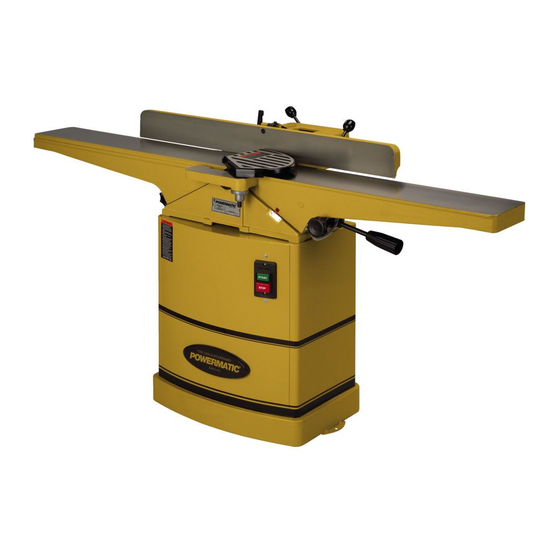
6" jointer
Hide thumbs
Also See for 54A:
- Brochure (3 pages) ,
- Operating instructions and parts manual (40 pages) ,
- Operating instructions and parts manual (70 pages)

Related Manuals for Powermatic 54A


Summary of Contents for Powermatic 54A
- Page 1 6" JOINTER Model 54A Instruction Manual & Parts List M-0460246 (800) 274-6848 www.powermatic.com...
-
Page 2: More Information
This manual has been prepared for the owner and operators of a Powermatic Model 54A, 6" Jointer. Its purpose, aside from machine operation, is to promote safety through the use of accepted correct operating and maintenance procedures. Completely read the safety and main- tenance instructions before operating or servicing the machine. -
Page 3: Table Of Contents
TABLE OF CONTENTS Safety: Instructions .............................. 4 Decals ..............................6 Specifications ..............................6 Receiving the Jointer ............................7 Installation ............................... 7 Mounting Jointer to Stand ........................7 Installing Belt ............................8 Installing Pulley Cover ..........................8 Fence Installation & Removal ........................8 Cutterhead Guard Installation &... -
Page 4: Safety Instructions
Read the manual. Read, understand, and follow the safety instructions found in this manual. Know the limita- tions and hazards in using the model 54A - 6" Jointer. Decals are placed on each machine as reminders of good safety practice. - Page 5 Direction of feed. Feed work into a blade or cutter against the direction of rotation of the blade or cutter only. Never leave machine running unattended. Turn power off. Don’t leave machine until it comes to a complete stop. Do not perform jointing operations on material shorter than 8", narrower than 3/4 inch, or less than 1/4 inch thick.
-
Page 6: Decals
Stand weight ............................64 lbs. Switch .............................. push button NOTE: The above specifications were current at the time this manual was published, but because of our policy of continuous improvement, Powermatic reserves the right to change specifications without notice and without incurring obligations. -
Page 7: Receiving The Jointer
RECEIVING THE JOINTER Upon delivery, open shipping containers and check that all parts are in good condition. Any damage should be reported to your distributor and shipping agent imme- Lock bolts Qty. 3 diately. Before proceeding further, read your manual and familiarize yourself thoroughly with assembly, Handle screw maintenance and safety procedures. -
Page 8: Installing Belt
INSTALLING BELT To attach the belt to the cutterhead pulley and motor pulley, first reach into the dust chute with a wrench and loosen the four bolts holding the motor to the mount bracket. Align the pulleys using the slotted holes on the mounting bracket. -
Page 9: Installing Dust Chute
Slightly turn knob (A), if necessary, until the guard seats itself, and the spring engages the slot at the end of the guard post. Check the guard for proper tension. If guard does not spring back into place when pulled back from cutterhead, remove guard and adjust spring tension by repeating steps 1-3 until correct tension is achieved. -
Page 10: Extension Cords
Grounded, cord-connected tools intended for use on a supply circuit having a nominal rating less than 150 volts: This tool is intended for use on a circuit that has an outlet that looks like the one illustrated in Sketch A, Figure 8. -
Page 11: Safety Switch
SAFETY SWITCH The jointer is equipped with a push-button switch with safety padlock, shown in Figure 10. To safe- guard your machine from unauthorized operation and accidental starting by young children, the use of the padlock is highly recommended. ADJUSTMENTS FIGURE 10 Tools required 8mm, 10mm 12mm, and 19mm wrenches... -
Page 12: Installing New Knives
Snug the two outside gib locking screws. If you have a Powermatic knife setting gauge, place it on the outfeed table and "0" the indicator as shown in Figure 15. Lift the gauge off the outfeed table to see how far below the bottom of the gauge the indicator travels. -
Page 13: Outfeed Table & Knives
If a Powermatic knife gauge is not available, use a standard shop scale. Stand the scale on its edge on the outfeed table; the scale should extend over the cutterhead. Using the above method, raise knife until it just touches the scale at the high point of the cutterhead arc. -
Page 14: Depth Of Cut
DEPTH OF CUT Depth of cut is determined by the height of the infeed table relative to the high point of the knives on the cutterhead. When facing the width of a board (as opposed to the edge of a board), NEVER attempt to take off more than 1/64"... -
Page 15: Table Gibs And Leveling
TABLE GIBS AND LEVELING The table gibs on your machine are factory adjusted and may never require readjustment. Should any adjustment become necessary, do the following: Lightly loosen the gib adjusting screws (A), Fig- ure 23. By loosening the lock nuts first the set screws should be loose enough to move the table. -
Page 16: Fence Adjustments: Stop
FENCE ADJUSTMENTS: STOP Periodically check the 90 degree and 45 degree tilt accuracy of the fence with a machinist’s protractor. If adjustments are necessary, do the following: 90 degree stop: The 90 degree stop is controlled by the hexago- nal stop screw (D), shown in Figure 25. Release the locking bolt (B). -
Page 17: Basic Operations
two handed push BASIC OPERATIONS block Before making any cuts on the stock, make a few practice cuts by raising the infeed table to “0" and with the power disconnected. In this manner you will acquaint yourself with the feel of jointer operations. SURFACING Adjust depth of cut. -
Page 18: Surfacing Long Boards
left hand pushes SURFACING: LONG BOARDS down toward fence as right hand The use of push blocks will help to insure against starts feed hands coming in contact with cutterhead in the event of a kickback and as trailing end of board passes over cutterhead. -
Page 19: Jointing (Or Edging)
1/4 inch thick and 1 inch wide. Set fence to desired angle. FIGURE 30a CAUTION: Although fence may be tilted in or out for bevel cut, POWERMATIC recommends for safety reasons the fence be tilted in, if possible, making a cradled cut (Fig. 30a). -
Page 20: Skewing (Shear Cutting)
Illustrated in Figure 32 are three types of push blocks commonly used in jointing. Push blocks may be obtained commercially or easily constructed. NOTE: The 54A Jointer is supplied with two hold- downs for feeding stock. FIGURE 32... -
Page 21: Optional Accessories
OPTIONAL ACCESSORIES (54A Jointer) 2004017 Dust Collector Adaptor 2042340 Mobile Base 6285860 Knives (set of 3) 6285917 Push Block 6285991 Tool Kit 2230035 Knife Setting Gauge... -
Page 22: Fence Assembly
Parts List : Fence Assembly (54A Jointer) Part No. Description Quantity 6296130 Fence Assembly ..................... 1 6296143 Locking Bolt ......................1 6296066 Flat Washer, 13mm x 28mm x 3mm ..............2 6296067 Stop Block ......................1 6296068 Fence Bracket ......................1 6285945 Knob ........................ -
Page 23: Fence Assembly
Fence Assembly (54A Jointer) -
Page 24: Base & Table Assembly
Parts List : Base & Table Assembly (54A Jointer) Part No. Description Quantity 6296086 Base Slide ........................1 6296087 Washer, 3/8 x 1 x 5/32 ....................4 6296088 Spring Pin, 4mm dia. x 14mm Lg ................1 6296089 Key, 9.5mm x 273 mm ....................1 6285931 Cap Screw, 3/8-16 x 1-1/2 .................. -
Page 25: Base & Table Assembly
Parts List : Base & Table Assembly (54A Jointer) 6285897 Screw, 5/32-32 x 5/8 ....................3 6296147 Depth Scale ......................... 1 6296148 Rivet ..........................2 6296151 Collar ..........................1 6296152 Set Screw, 1/4-20 UNC x 1/4 ..................2... -
Page 26: Cutterhead Assembly
Parts List : Cutterhead Assembly (54A Jointer) Part No. Description Quantity 6296074 Cutterhead Assembly....................1 6285852 Spring Washer, 3/8 x 5/8 ..................2 6285853 Stud ........................2 6285854 Bearing Housing ..................... 1 6285855 Bearing 6202-2NSE ....................1 6285856 Cutterhead ......................1 6285857 Key, 5mm x 5mm x 25mm .................. -
Page 27: Cutterhead Assembly
Cutterhead Assembly (54A Jointer) -
Page 28: Stand Assembly
Parts List : Stand Assembly (54A Jointer) Part No. Description Quantity 6296131 Stand Assembly ...................... 1 6296121 Stand ........................1 6285974 Door ........................1 6285822 Lock Bolt ........................ 3 6285852 Spring Washer, 3/8 x 5/8 ..................3 6296122 Screw, 1/8-40 x 3/8 ....................4 6296123 Flat Washer, 1/8 x 3/8 x 1/32 ................. -
Page 29: Stand Assembly
Stand Assembly (54A Jointer) - Page 31 Locating the EDP number of the part(s) required from your parts manual will also expedite your order. Phone No.: (800) 274-6848 Fax No. (800) 274-6840 If you are calling from Canada, please call 800-238-4746 E-mail: powermatic@powermatic.com Website: www.powermatic.com...
- Page 32 07/01 P.O. Box 1349 Auburn, WA 98071-1349 Phone: (800) 274-6848 Fax: (800) 274-6840 E-mail: powermatic@powermatic.com Website: www.powermatic.com POWERMATIC ALL RIGHTS RESERVED...
Need help?
Do you have a question about the 54A and is the answer not in the manual?
Questions and answers