Table of Contents
Advertisement
Quick Links
Advertisement
Table of Contents

Related Manuals for Powermatic 719T WMH


Summary of Contents for Powermatic 719T WMH
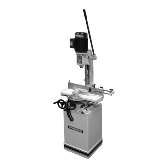
- Page 1 Operating Instructions and Parts Manual Tilting Table Hollow Chisel Mortiser Model: 719T WMH TOOL GROUP 2420 Vantage Drive Elgin, Illinois 60123 Part No. M-2474002 Ph.: 800-274-6848 Revision A 03/04 www.wmhtoolgroup.com Copyright © WMH Tool Group...
-
Page 2: Warranty And Service
This manual has been prepared for the owner and operators of a POWERMATIC 719T Tilting Table Hollow Chisel Mortiser. Its purpose, aside from machine operation, is to promote safety using accepted operating and maintenance procedures. To obtain maximum life and efficiency from your mortiser and to aid in using it safely, please read this manual thoroughly and follow the instructions carefully. -
Page 3: Table Of Contents
Table of Contents Warranty and Service... 2 Table of Contents... 3 Warnings ... 4 Introduction ... 6 Specifications ... 6 Unpacking ... 7 Contents of the Mortiser Carton ... 7 Contents of the Stand Carton... 7 Assembly... 8 Securing Machine to Stand ... 8 Wooden Table ... -
Page 4: Warnings
Warnings 1. Read and understand the entire owners manual before attempting assembly or operation. 2. Read and understand the warnings posted on the machine and in this manual. Failure to comply with all of these warnings may cause serious injury. 3. - Page 5 23. Maintain a balanced stance at all times so that you do not fall or lean against the chisel and drill bits or other moving parts. Do not overreach or use excessive force to perform any machine operation.
-
Page 6: Introduction
Introduction This manual is provided by POWERMATIC covering the safe operation and maintenance procedures for a Model 719T Tilting Table Hollow Chisel Mortiser. This manual contains instructions on installation, safety precautions, general operating procedures, maintenance instructions and parts breakdown. This machine has been designed and constructed to provide years of trouble free operation if used in accordance to instructions set forth in this manual. -
Page 7: Unpacking
Unpacking Remove mortiser and stand from the shipping cartons. Check for damage and ensure all parts are intact. Any damage should be reported immediately to your distributor and shipping agent. Read the manual thoroughly to familiarize yourself with the correct assembly and maintenance procedures and proper safety precautions. -
Page 8: Assembly
Assembly Do not connect the machine power source until assembled. Read and understand the entire manual. Securing Machine to Stand The mortiser should be secured to the stand with four M8 x 45 hex cap screws and M8 lock washers (provided) using the holes in the base. Make sure there is enough room on each side of the mortiser for the size stock you plan to use. -
Page 9: Installing Chisel And Bit
4. Tighten the lock screw to hold the chisel in place. 5. Push the bit up through the chisel opening as far as it will go. Lock the drill bit in place with the chuck key. 6. Loosen the lock screw and push the chisel up against the bushing, then tighten the lock screw. -
Page 10: Electrical
Electrical Power Connection machine locations. A separate electrical circuit should be used for your machines. This circuit should not be less than #12 wire and should be protected with a 20 Amp time lag fuse. If an extension cord is used, use only 3-wire extension cords which have 3-prong grounding type plugs and matching receptacle, which will accept the... -
Page 11: Adjustments
Adjustments 90° Chisel to Worktable Calibration Referring to Figure 7: Place a square (E) so it rests against the worktable (B) and chisel (A). If the chisel to table angle is 90°, no calibration is necessary. If calibration is required: 1. -
Page 12: Table Tilt Control
6. Reinstall the chisel bushing (F) and secure it loosely with the lock screw (E). 7. Reinstall the chisel and bit (refer to the Installing Chisel and Bit section). Depth Stop Rod Adjustment Referring to Figure 9: A depth stop rod (A) is provided to limit the depth of the chisel. -
Page 13: Chisel Parallel To Workpiece
Chisel Parallel to Workpiece Referring to Figure 11: The chisel can be adjusted parallel to the workpiece as follows: 1. With the left handwheel (A), move the table back far enough to insert the workpiece (B) between the chisel (D) and fence. 2. -
Page 14: Maintenance
Do not have the chisel slot against the blind end of the mortise, as the chips will not be able to clear the chisel. This can cause overheating and possible breakage of chisel or bit. When cutting deep mortises, make the cut in several stages of approximately 1"... -
Page 15: Lubrication
three turns of the cutter in a carpenter's brace chuck should be enough to sharpen the chisel, as shown in Figure 16. Use a small, triangular, smooth file to relieve the inner corners of the chisel (Figure 17). Remove any burrs from the outside of the chisel with a fine oilstone. -
Page 16: 719T Mortiser Parts List
719T Mortiser Parts List Index No. Part No. Description Size ...2474002T...719T Mortiser Assy (Items 1 thru 120) ..1 1 ...719T-101...Fixed Base ..1 2 ...6294125 ...Base, Middle ..1 3 ...6294126 ...Gib..1 4 ...TS-1523061 ...Socket Set Screw... M6×20... 3 5 ...TS-1540041 ...Hex Nut ... - Page 17 Index No. Part No. 57 ...6294180 ...C-Clip ..2 58 ...6294181 ...Depth Setting Block ..1 59 ...719T-159...Depth Setting Rod..1 60 ...6294183 ...Universal Handle..1 61 ...TS-1505041 ...Socket Head Cap Screw... M10×30... 4 62 ...TS-2361101 ...Lock Washer ... M10 ... 8 63 ...6294186 ...Clamping Jaw...
-
Page 18: 719T Mortiser Assembly
Index No. Part No. Description Size 114 ...TS-1491021 ...Hex Cap Screw ... M10 x 20 ... 4 115 ...719T-1115...Tilting Bracket ..1 116 ...TS-2342161 ...Hex Nut, Nylon Lock ... M16 ... 2 117 ...719T-1117...Wave Washer..2 118 ...719T-1118...Bolt ..2 119 ...719T-1119...Tilting Base ... -
Page 19: 719T Mortiser Stand Parts List
719T Mortiser Stand Parts List Index No. Part No..6294235T...Stand Assembly (Items 1 thru 8)..1 1 ...719T-201...Stand..1 2 ...719T-202...Shelf Cushion..1 ...6294236 ...Door Assembly (Items 3 thru 6) ..1 3 ...6294226 ...Door ..1 4 ...6294227 ...Pin ... -
Page 20: Optional Accessories
6 ...6285528 ...Chisel & Bit, 3/8" ..7 ...6285529 ...Chisel & Bit, 1/2" ..8 ...6294245 ...Chuck & Key, 1/2" ..9 ...6294198 ...Drill Bushing, 1-1/8" ..10 ...6294221 ...Drill Bushing, 3/4"..11 ...6294222 ...Drill Bushing, 5/8"..
Need help?
Do you have a question about the 719T WMH and is the answer not in the manual?
Questions and answers