Table of Contents
Advertisement
Quick Links
Advertisement
Table of Contents

Related Manuals for ALLNIC AUDIO T-1800 MK2


Summary of Contents for ALLNIC AUDIO T-1800 MK2
- Page 1 ALLNIC AUDIO T-1800 MK2 EL34 STEREO INTEGRATED AMPLIFIER OWNER’S MANUAL...
- Page 2 Thank you for purchasing the Allnic Audio T-1800 MK2 EL34 Stereo Integrated Amplifier. We are certain your trust in Allnic Audio and its dealers worldwide, as well as your appreciation for the sound of this high-quality device, will be rewarded by its excellent operation for years to come.
-
Page 3: Table Of Contents
TUBES SPECIFICATIONS WARRANTY FIGURES Please read about SAFETY before you attempt to use the T-1800 MK2 EL34 Integrated Amplifier - we care about our customers and the equipment, and we want you to enjoy this product for a long time! -
Page 4: Introducing The T-1800 Mk2
The T-1800 MK2 stereo integrated amplifier is Allnic Audio’s EL34 stereo integrated amplifier model. Like all Allnic Audio products, the T-1800 MK2 has Permalloy (iron and nickel alloy) for its transformer cores. Allnic is grateful to Mr. G.W. Elmen of Western Electric for inventing Permalloy for transformer core use, and in so doing, providing an enormous service to recorded music listeners everywhere. -
Page 5: What's In The Box
T-1800 MK2 in your system. Be sure the T-1800 MK2 is labeled for the AC voltage of your location. If it is not, DO NOT connect it to your AC outlet. Please contact your Allnic dealer. -
Page 6: Initial Set-Up
INITIAL SET-UP LOCATION, LOCATION, LOCATION Like all audio products using tubes, the Allnic Audio T-1800 MK2 needs to be placed on a solid stand in a location that provides good air circulation around, above and below the stereo amplifier. •... -
Page 7: Speaker Terminals
Turn on the T-1800 MK2 by pushing in the power switch button located at the front of the right-side chassis panel to the “on” position (See Figure 3). After about a thirty to forty (30 - 40) second delay (the soft start), the T-1800 MK2 will be powered on. -
Page 8: The Current Meters
If a meter’s needle drops below the left parallel line during operation, it indicates a failure of the related EL34 tube. You must turn off the T-1800 MK2 and replace the EL34. Check the meter for the other EL34 on that channel. If the meter needle is between the parallel lines, it is not necessary to replace that tube. -
Page 9: Specifications
Date of purchase is the date indicated on the invoice for the product issued by Allnic Audio or its authorized representative. For the warranty to be valid, a defective product must be returned to Allnic Audio’s authorized representative for service prior to any unauthorized attempt to repair. Any repair work on an Allnic Audio product not specifically authorized by Allnic Audio or its authorized representative will void the warranty on the product. -
Page 10: Figures
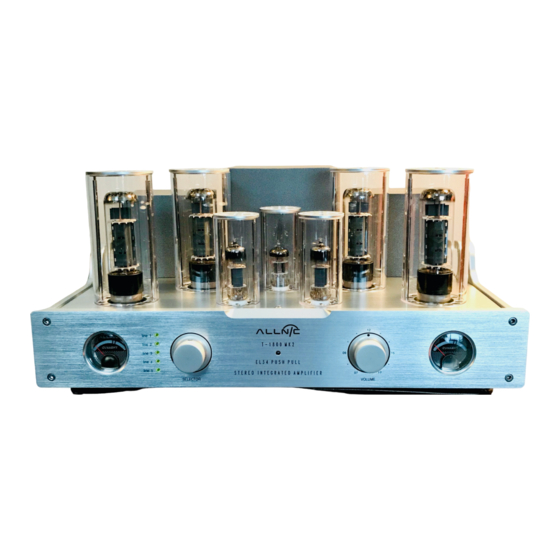
FIGURES Figure 1 – T-1800 MK2 EL34 Stereo Integrated Amplifier Front Panel View Figure 2 – T-1800 MK2 EL34 Stereo Integrated Amplifier Rear Panel View... - Page 11 Figure 3 – T-1800 MK2 EL34 Stereo Integrated Amplifier Right-side Panel View...
- Page 12 Figure 4 – T-1800 MK2 EL34 Stereo Integrated Amplifier Remote Control...
- Page 13 Figure 5 – T-1800 MK2 EL34 Stereo Integrated Amplifier Chassis Top View EL34 EL34...
Need help?
Do you have a question about the T-1800 MK2 and is the answer not in the manual?
Questions and answers