Table of Contents
Advertisement
Quick Links
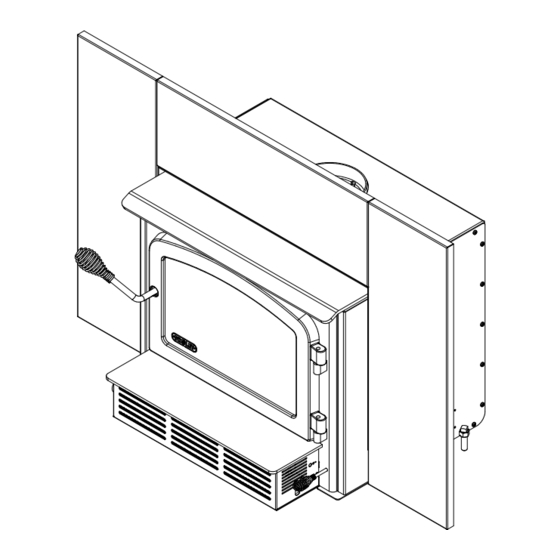
ESCAPE 1500-I
(DB03137 model)
CONTACT LOCAL BUILDING OR FIRE OFFICIALS ABOUT RESTRICTIONS AND INSTALLATION INSPECTION REQUIREMENTS
IN THE AREA.
READ THIS ENTIRE MANUAL BEFORE INSTALLATION AND USE OF THIS WOOD INSERT. FAILURE TO FOLLOW THESE
INSTRUCTIONS COULD RESULT IN PROPERTY DAMAGE, BODILY INJURY OR EVEN DEATH.
READ AND KEEP THIS MANUAL FOR REFERENCE
Printed in Canada
Wood Insert
Owner's Manual
Part 2 of 2
INSTALLATION AND
OPERATION REQUIREMENTS
Safety tested according to
CAN/ULC 628, UL 1482 and
UL 737 by an accredited
US Environmental Protection
Agency phase II certified
wood insert compliant with
2020 cord wood standard.
laboratory.
EPA
< ≤
2.5
g/h
45997_IA
Advertisement
Table of Contents

Related Manuals for Drolet ESCAPE 1500-I


Summary of Contents for Drolet ESCAPE 1500-I
- Page 1 Wood Insert Owner's Manual Part 2 of 2 INSTALLATION AND OPERATION REQUIREMENTS ESCAPE 1500-I (DB03137 model) Safety tested according to CAN/ULC 628, UL 1482 and UL 737 by an accredited laboratory. US Environmental Protection Agency phase II certified wood insert compliant with 2020 cord wood standard.
- Page 2 It is also highly recommended to register the warranty online at https://www.drolet.ca/en/warranty/warranty-registration/ Registering the warranty will help to quickly find the information needed on the unit.
-
Page 3: Table Of Contents
Optional Fresh Air Intake Kit Installation...............23 Optional Fire Screen Installation ..................24 Log Retainers Installation ...................26 Air Tubes and Baffle Installation ..................27 Removal Instructions ....................30 Exploded Diagram and Parts List ................31 DROLET LIMITED LIFETIME WARRANTY ................. 34 Product Specification Manual - Escape 1500-I Page 3... -
Page 4: Certification Plate
1. CERTIFICATION PLATE Page 4 Product Specification Manual - Escape 1500-I... -
Page 5: General Information
This appliance is officially tested and certified by an independent agency. Tested and certified in compliance with CFR 40 part 60, subpart AAA, section 60.534(a)(1(ii) and ASTM E3053-17. Based on EPA letter dated November 1, 2022. Carbon monoxide. Product Specification Manual - Escape 1500-I Page 5... -
Page 6: Specifications
CAN/CSAZ240 MH standard. Tested and certified in compliance with CFR 40 part 60, subpart AAA, section 60.534(a)(1(ii) and ASTM E3053-17. Based on EPA letter dated November 1, 2022. Page 6 Product Specification Manual - Escape 1500-I... -
Page 7: Dimensions
15 3/4" 400mm 24 1/4" 6 5/8" 616mm 169mm 16 1/2" 419mm 17 5/8" 446mm 22 3/8" 569mm Figure 3 : Front View Figure 4 : Side View - Maximum Insert Projection Product Specification Manual - Escape 1500-I Page 7... - Page 8 Figure 5 : Door Opening 5/16" 3/16" 11 7/8" 19 5/8" 301mm 498mm 13 1/2" 343mm Figure 6 : Front View - Combustion Chamber Figure 7 : Side View - Combustion Chamber Page 8 Product Specification Manual - Escape 1500-I...
- Page 9 The front (3rd) piece should stand off on the steel andirons by approximately 1-2 inches. The 2 other pieces should be added on top of the first Product Specification Manual - Escape 1500-I Page 9...
- Page 10 4 inches cross section dimensions approximately) on top. To make sure combustion is equal, put the smallest piece on top of the first three, at the back of the firebox (see Figure 16 for an example of low burn load). Page 10 Product Specification Manual - Escape 1500-I...
- Page 11 For optimal medium fire load, use medium to large size fuel pieces (between 4- and 5.5-inches cross section dimensions approximately) on the bottom and use small to medium size fuel pieces (2.5 to 4 inches cross section dimensions approximately) on top. To make sure combustion is Product Specification Manual - Escape 1500-I Page 11...
- Page 12 4 and 15 minutes after the loading period. Before closing further, make sure the flame intensity is increasing or stable. Turn ON the blower at maximum speed. Page 12 Product Specification Manual - Escape 1500-I...
-
Page 13: Clearances To Combustible Material
27 ½" (700 mm) 12 ¾" (324 mm) If a fresh air intake is required, it is recommended to add at least 4" to the width of the minimum opening of the hearth. Product Specification Manual - Escape 1500-I Page 13... -
Page 14: Floor Protection
(406 mm USA) and at least 18" (457 mm Canada) without an R value. If the hearth elevation is lower than 5" (127 mm), the non-combustible (B) floor protection in front of the insert should have an R value equal or greater than 1.00 and shall extend 23" (584 mm) in front of the unit. Page 14 Product Specification Manual - Escape 1500-I... -
Page 15: R Value
0.51 Hardibacker® 500 0.44 Wonderboard® 3.23 0.31 Cement mortar 5.00 Common brick 5.00 Face brick 9.00 0.11 Marble 14.3 – 20.00 0.07 – 0.05 Information as reported by manufacturers and other resources. Product Specification Manual - Escape 1500-I Page 15... - Page 16 K value = 0.75 Thickness = 1 R value = Thickness/K = 1/0.75 = 1.33 Horizontal still air can’t be «stack» to accumulate R-values; each layer must be separated with another non-combustible material. Page 16 Product Specification Manual - Escape 1500-I...
-
Page 17: Installing Options On Your Product And Replacing Parts
Remove the split pin by pulling and turning it using pliers. Turn the handle one counterclockwise turn to increase pressure. Reinstall the split pin with a small hammer. Figure 20 : Removing the split pin Figure 21 : Installing the split pin Product Specification Manual - Escape 1500-I Page 17... - Page 18 Using a flat screwdriver, turn the adjustable hinge rods in the direction shown to adjust the doors. Tighten all door hinge pressure screws when they are at the desired positions. Configurations 1-2-3-4-5-6, show in which direction these act on the adjustment of the door. Page 18 Product Specification Manual - Escape 1500-I...
- Page 19 (see procedure below). Reinstall the glass, being careful to centre the glass in the door and not to over-tightening the retaining screw. Figure 22 : Replacing the glass Product Specification Manual - Escape 1500-I Page 19...
-
Page 20: Blower And Ash Lip Installation
Blower and Ash Lip Installation Install the ash lip (A) on the insert with Center the blower on the ash lip and push three screws (B). it against the firebox. Then push it until it clips. Page 20 Product Specification Manual - Escape 1500-I... -
Page 21: Faceplate Installation
Lay the panels on a flat and non abrasive surface. Align the top panel holes (L) with the left (N) and right (M) panels. Secure together using the four bolts (P) and nuts (O) provided. Product Specification Manual - Escape 1500-I Page 21... - Page 22 (R). Then push towards the fireplace. Once the faceplate is in place, secure the assembly by tightening nuts (S) using a 7/16" (11 mm) open end wrench. Page 22 Product Specification Manual - Escape 1500-I...
-
Page 23: Optional Fresh Air Intake Kit Installation
Install the plate (K) with four screws (L) on the unused side of the insert. he pipe must be HVAC type, insulated, and must comply with ULC S110 and/or UL 181, Class 0 or Class 1. Product Specification Manual - Escape 1500-I Page 23... -
Page 24: Optional Fire Screen Installation
In the United States or in provinces with a particulate emissions limit (e.g.: US EPA), the use of open- door wood stoves with a rigid firescreen is prohibited. Open the door. Hold the fire screen by the two handles and bring it close to the door opening. Page 24 Product Specification Manual - Escape 1500-I... - Page 25 Lift the fire screen upwards and push the bottom part towards the insert then let the fire screen rest on the bottom of the door opening. Warning: Never leave the insert unattended while in use with the fire screen. Product Specification Manual - Escape 1500-I Page 25...
-
Page 26: Log Retainers Installation
Log Retainers Installation Page 26 Product Specification Manual - Escape 1500-I... -
Page 27: Air Tubes And Baffle Installation
Air Tubes and Baffle Installation Starting with the rear tube, lean and insert the right end of the secondary air tube into the rear right channel hole. Then lift and insert the left end of the tube into the rear left channel. Align the notch in the left end of the tube with the key of the left air channel hole. - Page 28 Note that secondary air tubes (A) can be replaced without removing the baffle board (B) and that all tubes are identical.
-
Page 30: Removal Instructions
Removal Instructions For inspecting purposes, the insert may need to be removed. To remove the insert, follow these instructions: Unscrew the faceplate fastener (B) holding the faceplate (C) on the insert. Remove faceplate (C) by pulling on it. Remove the blower assembly (D). Remove the three screws securing the pipe connector (A). -
Page 31: Exploded Diagram And Parts List
Exploded Diagram and Parts List... - Page 32 IMPORTANT: THIS IS DATED INFORMATION. When requesting service or replacement parts for this unit, please provide the model number and the serial number. We reserve the right to change parts due to technology upgrades or availability. Contact an authorized dealer to obtain any of these parts.
- Page 33 Item Description PL70696 FACEPLATE 29 X 44 TOP PANEL PL70695 FACEPLATE 29 X 44 SIDE PANEL SE70696 ESCAPE 1500 INSERT FACEPLATE SE70656 BLOWER ASSEMBLY 44089 DOUBLE CAGE BLOWER 144 CFM 115V - 60Hz - 1.1A 60013 POWER CORD 96" X 18-3 type SJT (50 pcs per carton) 44080 RHEOSTAT WITHOUT NUT (MODEL KBMS-13BV) 44087...
-
Page 34: Drolet Limited Lifetime Warranty
Shall your unit or a component be defective, contact immediately your DROLET dealer. To accelerate processing of your warranty claim, make sure to have on hand the following information when calling: •... - Page 36 Resale is strictly prohibited. The manufacturer may update St-Augustin-de-Desmaures (Québec) Canada this document from time to time and cannot be responsible G3A 2H3 for problems, injuries, or damages arising out of the use 1-877-356-6663 of information contained in any document obtained from https://www.drolet.ca/en/ unauthorized sources. tech@sbi-international.com...
Need help?
Do you have a question about the ESCAPE 1500-I and is the answer not in the manual?
Questions and answers